

SONY LCD TV KDL-40V2500 KDL-46V2500 KDL-46V25L1
What's Included?
Fast Download Speeds
Online & Offline Access
Access PDF Contents & Bookmarks
Full Search Facility
Print one or all pages of your manual
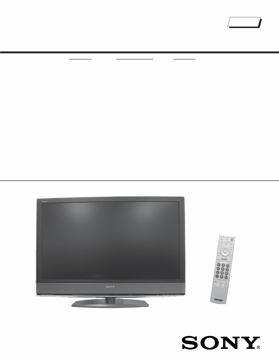
LCD DIGITAL COLOR TELEVISION
SERVICE MANUAL WAX2F CHASSIS
MODEL NAME REMOTE COMMANDER DESTINATION
9-883-722-03
KDL-40V2500 RM-YD012 CANADA
KDL-40V2500 RM-YD012 US
KDL-46V2500 RM-YD012 CANADA
KDL-46V2500 RM-YD012 US
KDL-46V25L1 RM-YD012 US
HISTORY INFORMATION FOR THE FOLLOWING MANUAL:
ORIGINAL MANUAL ISSUE DATE: 9/2006
☛
:UPDATED ITEM
REVISION DATE SUBJECT
9/2006 No revisions or updates are applicable at this time.
9/2006 Added APPENDIX A: ENCRYPTION KEY COMPONENTS to service manual. Added Page A-1
Updated Table of Contents. Replaced page 3
Updated Encryption Key notes. Replaced pages 23, 54-58, and 64
1/2007 Updated Block Diagram to show correct Boards. Replaced page 25.
LCD DIGITAL COLOR TELEVISION
SERVICE MANUAL WAX2F CHASSIS
MODEL NAME REMOTE COMMANDER DESTINATION
9-883-722-03
KDL-40V2500 RM-YD012 CANADA
KDL-40V2500 RM-YD012 US
KDL-46V2500 RM-YD012 CANADA
KDL-46V2500 RM-YD012 US
KDL-46V25L1 RM-YD012 US
Self Diagnosis
Supported model
KDL-40V2500 RM-YD012

3 KDL-40V2500/46V2500/46V25L1
KDL-40V2500/46V2500/46V25L1
TABLE OF CONTENTS
SECTION TITLE PAGE SECTION TITLE PAGE
Specifications ................................................................................. 4
Warnings and Cautions .................................................................. 6
Safety-Related Component Warning .............................................. 7
Safety Check-Out ........................................................................... 9
Self-Diagnostic Function............................................................... 10
SECTION 1: DISASSEMBLY............................................................... 12
1-1. Rear Cover Removal ............................................... 12
1-2. Vesa Bracket Assembly and Stand Removal........... 13
1-3. H1U Board Removal ................................................ 14
1-4. G2A Board Removal ................................................ 14
1-5. H2U Board Removal ................................................ 15
1-6. AU Board Removal .................................................. 15
1-7. QT Board Removal .................................................. 16
1-8. H3U Board and Speaker Removal .......................... 16
1-9. QSF board and BU Board Removal ........................ 17
1-10. LCD Panel Removal ................................................ 18
SECTION 2: SERVICE ADJUSTMENTS ............................................. 19
2-1. Remote Adjustment Buttons and Indicators ......................... 19
2-2. Accessing Service Adjustments ........................................... 19
2-2-1. Accessing the Digital Service Adjustment Menus .... 19
2-2-2. Viewing the Digital Module Box (Q-Box)
Service Items ........................................................... 20
2-2-3. Accessing the Analog Service Adjustment Menus ... 20
2-3. Resetting the User Menu - Factory Reset ............................ 21
2-4. Aging Mode .......................................................................... 21
2-5. White Balance Adjustment. .................................................. 22
SECTION 3: DIAGRAMS ..................................................................... 23
3-1. Circuit Boards Location ........................................................ 23
3-2. Printed Wiring Boards and
Schematic Diagrams Information ......................................... 23
3-3. Block Diagram ...................................................................... 25
3-4. Schematics and Supporting Information .............................. 26
AU Board Schematic Diagram (1 of 2) ................................. 26
AU Board Schematic Diagram (2 of 2) ................................. 27
BU Board Schematic Diagram (1 of 9) ................................. 29
BU Board Schematic Diagram (2 of 9) ................................. 30
BU Board Schematic Diagram (3 of 9) ................................. 31
BU Board Schematic Diagram (4 of 9) ................................. 32
BU Board Schematic Diagram (5 of 9) ................................. 33
BU Board Schematic Diagram (6 of 9) ................................. 34
BU Board Schematic Diagram (7 of 9) ................................. 35
BU Board Schematic Diagram (8 of 9) ................................. 36
BU Board Schematic Diagram (9 of 9) ................................. 37
G2A Board Schematic Diagram ........................................... 39
H1U Board Schematic Diagram ........................................... 41
H2U Board Schematic Diagram ........................................... 42
H3U Board Schematic Diagram ........................................... 44
QSF Board Schematic Diagram (1 of 5) .............................. 45
QSF Board Schematic Diagram (2 of 5) .............................. 46
QSF Board Schematic Diagram (3 of 5) .............................. 47
QSF Board Schematic Diagram (4 of 5) .............................. 48
QSF Board Schematic Diagram (5 of 5) .............................. 49
QT Board Schematic Diagram ............................................. 51
3-5. Semiconductors ................................................................... 53
SECTION 4: EXPLODED VIEWS ........................................................ 54
4-1. Rear Cabinet and Stand Assembly ..................................... 54
4-2. Chassis ............................................................................... 55
4-3. Speakers .............................................................................. 56
4-4. LCD Panel ............................................................................ 57
SECTION 5: ELECTRICAL PARTS LIST ............................................ 58
APPENDIX A: ENCRYPTION KEY COMPONENTS .......................... A-1
4
KDL-40V2500/46V2500/46V25L1
KDL-40V2500/46V2500/46V25L1
SPECIFICATIONS
Design and specifications are subject to change without notice.
120V-240V AC, 50/60Hz
200W (KDL-40V2500 Only)
240W (KDL-46V2500/46V25L1 Only)
Less than 0.1W
Video (IN) 1/2/3:
S Video (4-Pin Mini DIN (VIDEO 1/2 Only):
Y: 1.0 Vp-p, 75 ohms unbalanced, sync negative
C: 0.286 Vp-p (Burst signal), 75 ohms
Video:
1.0 Vp-p, 75ohms unbalanced, sync negative
Audio:
500 mVrms (100% modulation)
Impedance:47 kilohms
HD/DVD IN 4/5:
YP
B
P
R
(Component Video):
Y:1.0 Vp-p, 75 ohms unbalanced, sync negative
P
B
:0.7 Vp-p, 75 ohms
P
R
:0.7 Vp-p, 75 ohms
Signal format: 480i, 480p, 720p, 1080i
AUDIO:
500 mVrms (100% modulation)
Impedance: 47 kilohms
Power Requirements:
Power Consumption (W):
In Use (Max):
In Standby :
HDMI IN 6/7:
HDMI: Video:480i, 480p, 720p, 1080i, 1080p
Audio: Two channel linear PCM 32, 44.1 and
48 kHz, 16, 20 and 24 bits
AUDIO (HDMI IN 6 Only):
500 mVrms (100% modulation)
Impedance: 47 kilohms
AUDIO OUT:
500 mVrms (100% modulation)
More than 1 Vrms at the maximum volume setting (Variable)
More than 500 mVrms (Fixed)
PC IN 8:
D-sub 15-pin, analog RGB, 0.7 Vp-p, 75 ohms, positive
PC AUDIO INPUT:
Stereo mini jack, 0.5 Vrms, 1 kilohm
Headphones:
Stereo mini jack
Impedance: 16 ohms
Speaker:
Full range: 5.5 × 15 cmm (2
1/4
× 6 inches) (2) (KDL-40V2500)
Full range: 7 × 13 cm (2
3/4
× 5
7/16
inches) (2)
(KDL-46V2500/46V25L1)
Trademark Information
TruSurround XT, SRS and ( ) symbol are trademarks of SRS Labs, Inc.
TruSurround XT technology is incorporated under license from SRS Labs,
Inc.
Manufactured under license from BBE Sound, Inc.
Licensed by BBE Sound, Inc. under one or more of the following US
patents: 5510752, 5736897. BBE and BBE symbol are registered
trademarks of BBE Sound, Inc.
Macintosh is a trademark licensed to Apple Computer, Inc., registered in
the U.S.A and other countries.
“BRAVIA” and are trademarks of Sony Corporation.
As an ENERGY STAR
®
Partner, Sony Corporation has
determined that this product meets the ENERGY STAR
®
guidelines for energy efficiency.
ENERGY STAR
®
is a U.S. registered mark.
This TV incorporates High-Definition
Multimedia Interface (HDMI™) technology.
HDMI, the HDMI logo and High-Definition Multimedia Interface are
trademarks or registered trademarks of HDMI Licensing, LLC.
Manufactured under license from Dolby
Laboratories. “Dolby” and the double-D symbol are
trademarks of Dolby Laboratories.
5
KDL-40V2500/46V2500/46V25L1
KDL-40V2500/46V2500/46V25L1
Television system
American TV Standard
ATSC compliant 8VSB
ANSI/SCTE 07 2000
(Does not include CableCARD functionality)
Channel coverage
Analog Digital
Terrestrial 2-69 2-69
Cable 1-125 1-135
Antenna
75-ohm external terminal for VHF/UHF
Panel System
LCD (Liquid Crystal Display) Panel
Display Resolution (horizontal x vertical):
1,920 dots x 1,080 lines
Screen Size (measured diagonally)
40 inches (KDL-40V2500 Only)
46 inches (KDL-46V2500/46V25L1 Only)
Supplied Accessories
Remote Commander RM-YD012
Two Size AA (R6) Batteries
75-ohm coaxial cable
AC Power Cord
HD15-HD15 Cable
Suport Belt, Securing Screw, and Wood Screw
Cable Holder
Operating Instructions
Quick Setup Guide
Warranty Card
Optional Accessories
Headphones Plug Adaptor
Connecting Cables
Wall-Mount Bracket
SU-WL51
6
KDL-40V2500/46V2500/46V25L1
KDL-40V2500/46V2500/46V25L1
WARNINGS AND CAUTIONS
CAUTION
These servicing instructions are for use by qualified service personnel only. To reduce the risk of electric shock, do not perform any
servicing other than that contained in the operating instructions unless you are qualified to do so.
WARNING!!
An isolation transformer should be used during any service to avoid possible shock hazard, because of live chassis. The chassis of
this receiver is directly connected to the ac power line.
!
SAFETY-RELATED COMPONENT WARNING!!
Components identified by shading and
!
mark on the schematic diagrams, exploded views, and in the parts list are critical for
safe operation. Replace these components with Sony parts whose part numbers appear as shown in this manual or in supplements
published by Sony. Circuit adjustments that are critical for safe operation are identified in this manual. Follow these procedures
whenever critical components are replaced or improper operation is suspected.
ATTENTION!!
Ces instructions de service sont à l’usage du personnel de service qualifié seulement. Pour prévenir le risque de choc électrique, ne
pas faire l’entretien autre que celui contenu dans le Mode d’emploi à moins que vous soyez qualifié faire ainsi.
Afin d’eviter tout risque d’electrocution provenant d’un chássis sous tension, un transformateur d’isolement doit etre utilisé lors de tout
dépannage. Le chássis de ce récepteur est directement raccordé à l’alimentation du secteur.
!
ATTENTION AUX COMPOSANTS RELATIFS A LA SECURITE!!
Les composants identifies par une trame et par une marque
!
sur les schemas de principe, les vues explosees et les listes de
pieces sont d’une importance critique pour la securite du fonctionnement. Ne les remplacer que par des composants Sony dont
le numero de piece est indique dans le present manuel ou dans des supplements publies par Sony. Les reglages de circuit dont
l’importance est critique pour la securite du fonctionnement sont identifies dans le present manuel. Suivre ces procedures lors de
chaque remplacement de composants critiques, ou lorsqu’un mauvais fonctionnement suspecte.
7
KDL-40V2500/46V2500/46V25L1
KDL-40V2500/46V2500/46V25L1
SAFETY-RELATED COMPONENT WARNING
There are critical components used in LCD color TVs that are important for safety. These components are identified with shading and
!
mark on the schematic diagrams and the electrical parts list. It is essential that these critical parts be replaced only with the part number
specified in the electrical parts list to prevent electric shock, fire, or other hazard.
NOTE: Do not modify the original design without obtaining written permission from the manufacturer or you will void the original parts and
labor guarantee.
USE CAUTION WHEN HANDLING THE LCD PANEL
When repairing the LCD panel, be sure you are grounded by using a wrist band.
When installing the LCD panel on a wall, the LCD panel must be secured using the 4 mounting holes on the rear cover.
To avoid damaging the LCD panel:
do not press on the panel or frame edge to avoid the risk of electric shock.
do not scratch or press on the panel with any sharp objects.
do not leave the module in high temperatures or in areas of high humidity for an extended period of time.
do not expose the LCD panel to direct sunlight.
avoid contact with water. It may cause a short circuit within the module.
disconnect the AC adapter when replacing the backlight (CCFL) or inverter circuit.
(High voltage occurs at the inverter circuit at 650Vrms.)
always clean the LCD panel with a soft cloth material.
use care when handling the wires or connectors of the inverter circuit. Damaging the wires may cause a short.
protect the panel from ESD to avoid damaging the electronic circuit (C-MOS).
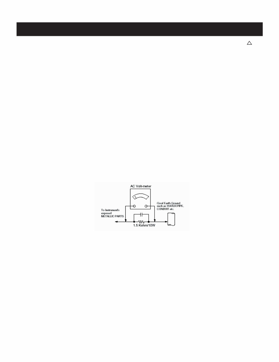
LEAKAGE CURRENT HOT CHECK CIRCUIT
8
KDL-40V2500/46V2500/46V25L1
KDL-40V2500/46V2500/46V25L1
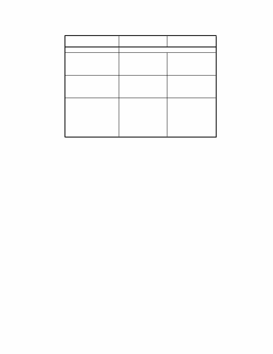
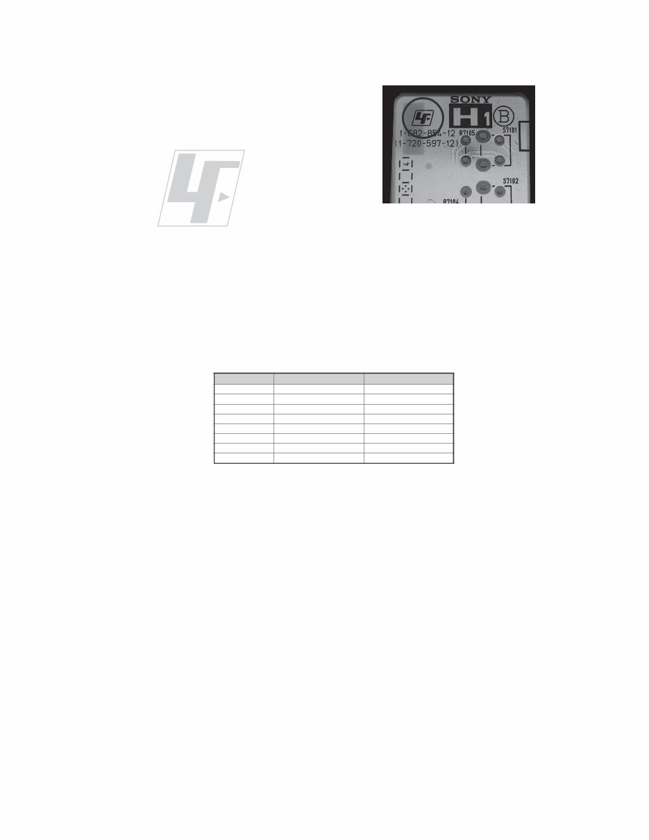
The circuit boards used in these models have been processed using
Lead Free Solder. The boards are identified by the LF logo located
close to the board designation e.g. H1 etc [ see example ]. The
servicing of these boards requires special precautions to be taken as
outlined below.
example 1
It is strongly recommended to use Lead Free Solder material in order to guarantee optimal quality of new solder joints.
Lead Free Solder is available under the following part numbers :
Due to the higher melting point of Lead Free Solder the soldering iron tip temperature needs to be set to 370 degrees centigrade.
This requires soldering equipment capable of accurate temperature control coupled with a good heat recovery characteristics.
For more information on the use of Lead Free Solder, please refer to http://www.sony-training.com
r e b m u n t r a P r e t e m a i D s k r a m e R
9 1 - 5 0 0 - 0 4 6 - 7 m m 3 . 0 g K 5 2 . 0
0 2 - 5 0 0 - 0 4 6 - 7 m m 4 . 0 g K 0 5 . 0
1 2 - 5 0 0 - 0 4 6 - 7 m m 5 . 0 g K 0 5 . 0
2 2 - 5 0 0 - 0 4 6 - 7 m m 6 . 0 g K 5 2 . 0
3 2 - 5 0 0 - 0 4 6 - 7 m m 8 . 0 g K 0 0 . 1
4 2 - 5 0 0 - 0 4 6 - 7 m m 0 . 1 g K 0 0 . 1
5 2 - 5 0 0 - 0 4 6 - 7 m m 2 . 1 g K 0 0 . 1
6 2 - 5 0 0 - 0 4 6 - 7 m m 6 . 1 g K 0 0 . 1
9
KDL-40V2500/46V2500/46V25L1
KDL-40V2500/46V2500/46V25L1
SAFETY CHECK-OUT
After correcting the original service problem, perform the following
safety checks before releasing the set to the customer:
1. Check the area of your repair for unsoldered or poorly soldered
connections. Check the entire board surface for solder splashes and
bridges.
2. Check the interboard wiring to ensure that no wires are “pinched” or
touching high-wattage resistors.
3. Check that all control knobs, shields, covers, ground straps, and
mounting hardware have been replaced. Be absolutely certain that
you have replaced all the insulators.
4. Look for unauthorized replacement parts, particularly transistors,
that were installed during a previous repair. Point them out to the
customer and recommend their replacement.
5. Look for parts which, though functioning, show obvious signs of
deterioration. Point them out to the customer and recommend their
replacement.
6. Check the line cords for cracks and abrasion. Recommend the
replacement of any such line cord to the customer.
7. Check the antenna terminals, metal trim, “metallized” knobs, screws,
and all other exposed metal parts for AC leakage. Check leakage as
described below.
Leakage Test
The AC leakage from any exposed metal part to earth ground and
from all exposed metal parts to any exposed metal part having a
return to chassis, must not exceed 0.5 mA (500 microamperes).
Leakage current can be measured by any one of three methods.
1. A commercial leakage tester, such as the Simpson 229 or RCA
WT-540A. Follow the manufacturers’ instructions to use these
instructions.
2. A battery-operated AC milliampmeter. The Data Precision 245
digital multimeter is suitable for this job.
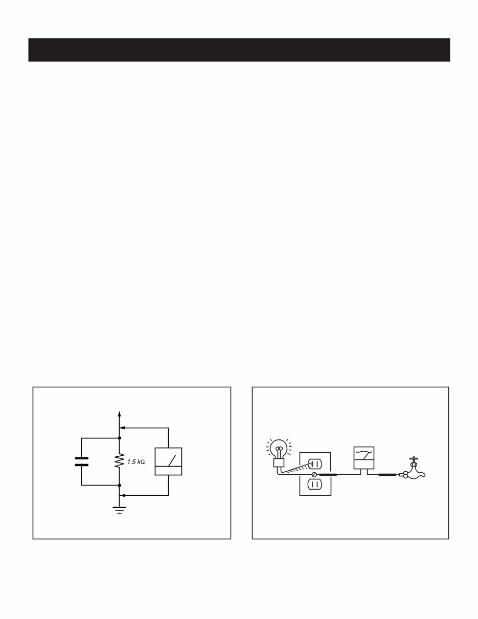
3. Measuring the voltage drop across a resistor by means of a VOM
or battery-operated AC voltmeter. The “limit” indication is 0.75
V, so analog meters must have an accurate low voltage scale.
The Simpson’s 250 and Sanwa SH-63TRD are examples of
passive VOMs that are suitable. Nearly all battery-operated digital
multimeters that have a 2 VAC range are suitable (see Figure A).
How to Find a Good Earth Ground
A cold-water pipe is a guaranteed earth ground; the cover-plate
retaining screw on most AC outlet boxes is also at earth ground. If the
retaining screw is to be used as your earth ground, verify that it is at
ground by measuring the resistance between it and a cold-water pipe
with an ohmmeter. The reading should be zero ohms.
If a cold-water pipe is not accessible, connect a 60- to 100-watt
trouble- light (not a neon lamp) between the hot side of the receptacle
and the retaining screw. Try both slots, if necessary, to locate the hot
side on the line; the lamp should light at normal brilliance if the screw
is at ground potential (see Figure B).
To Exposed Metal
Parts on Set
0.15 µF
Earth Ground
AC
Voltmeter
(0.75V)
Trouble Light
AC Outlet Box
Ohmmeter
Cold-water Pipe
Figure A. Using an AC voltmeter to check AC leakage. Figure B. Checking for earth ground.
10
KDL-40V2500/46V2500/46V25L1
KDL-40V2500/46V2500/46V25L1
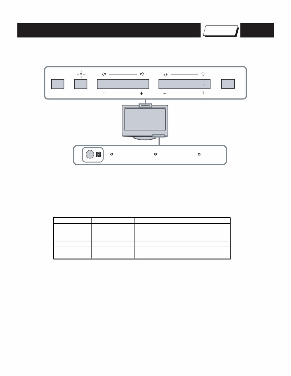
SELF-DIAGNOSTIC FUNCTION
Self Diagnosis
Supported model
Control Buttons
PIC OFF/TIMER STANDBY POWER
TV/VIDEO VOLUME
MENU
CHANNEL POWER
Description of LED Indictors
LED LED Type Description
* Light is green when the TV set is on
* Functions as failure indicator
* Blinks green in aging mode
TIMER LED Red LED Lights when timer is set
PIC OFF LED Green LED
Lights when power saving setting is set to
picture off (See Instruction Manual)
POWER LED Red/Green LED
You're Reading a Preview
What's Included?
Fast Download Speeds
Online & Offline Access
Access PDF Contents & Bookmarks
Full Search Facility
Print one or all pages of your manual
$30.99
$40.99
Viewed 26 Times Today


Secure transaction
What's Included?
Fast Download Speeds
Online & Offline Access
Access PDF Contents & Bookmarks
Full Search Facility
Print one or all pages of your manual
$30.99
$40.99
You are purchasing a Service Manual for a SONY LCD HD Television.
The Service Manual is in Adobe PDF format. You can view it on your computer using the Adobe Reader program (free from www.adobe.com).
DETAILS:
- Archive File Size: 19.4MB
- Format: Adobe PDF
- Number of Pages: 88
- Models Covered: KDL-40V2500, KDL-46V2500, KDL-46V25L1
- Quality: Excellent
CONTENTS OF THIS SERVICE MANUAL:
- DISASSEMBLY / REASSEMBLY
- SERVICE ADJUSTMENTS
- DIAGRAMS
- LARGE DIAGRAMS
- REPLACEMENT PARTS/PARTS LIST


