SERVICE MANUAL LC-40/46/52/60LE835U/830U/832U/LC-60LE831U Parts marked with " " are important for maintaining the safety of the set. Be sure to replace these parts with specified ones for maintaining the safety and performance of the set. This document has been published to be used for after sales service only. The contents are subject to change without notice. SAFETY PRECAUTION IMPORTANT SERVICE SAFETY PRECAUTION..............i PRECAUTIONS A PRENDRE LORS DE LA REPARATION .............................................. ii PRECAUTIONS FOR USING LEAD-FREE SOLDER........... iii OUTLINE MAJOR SERVICE PARTS ............................... iv CHAPTER 1. SPECIFICATIONS [1] SPECIFICATIONS (LC-40/46LE835U/830U/832U) ........ 1-1 [2] SPECIFICATIONS (LC-52/60LE835U/ 830U/832U/LC-60LE831U) ........................... 1-2 CHAPTER 2. OPERATION MANUAL [1] Parts Name ................................................... 2-1 [2] OPERATION MANUAL ................................. 2-3 CHAPTER 3. DIMENSIONS [1] DIMENSIONS (LC-40LE835U/830U/832U)........ 3-1 [2] DIMENSIONS (LC-46LE835U/830U/832U)........ 3-2 [3] DIMENSIONS (LC-52LE835U/830U/832U)........ 3-3 [4] DIMENSIONS (LC-60LE835U/830U/831U/832U) ........ 3-4 CHAPTER 4. REMOVING OF MAJOR PARTS [1] REMOVING OF MAJOR PARTS (LC-40LE835U/830U/832U) .......................... 4-1 [2] REMOVING OF MAJOR PARTS (LC-46LE835U/830U/832U) .......................... 4-6 [3] REMOVING OF MAJOR PARTS (LC-52LE835U/830U/832U) ........................ 4-11 [4] REMOVING OF MAJOR PARTS (LC-60LE835U/830U/831U/832U) ............... 4-16 [5] The location putting on the heat measure sheet ...... 4-21 [6] Precautions for assembly ............................ 4-24 [7] The way of detaching Rear Cabinet ............ 4-26 CHAPTER 5. ADJUSTMENT [1] ADJUSTMENT PROCEDURE ...................... 5-1 [2] PUBLIC MODE SETTING PROCEDURE....... 5-16 CHAPTER 6. TROUBLESHOOTING TABLE [1] Failure diagnosis by LED in front of cabinet ........ 6-1 [2] LED flashing specification at the time of an error (Center icon LED used) ........................ 6-1 [3] TROUBLESHOOTING TABLE ...................... 6-5 CHAPTER 7. MAJOR IC INFORMATIONS [1] MAJOR IC INFORMATIONS ......................... 7-1 CHAPTER 8. OVERALL WIRING/SYSTEM BLOCK DIAGRAM [1] OVERALL WIRING DIAGRAM (LC-40/46/52/60LE835U) .............................. 8-1 [2] OVERALL WIRING DIAGRAM (LC-40/46/ 52/60LE830U/832U/LC-60LE831U) .............. 8-2 [3] SYSTEM BLOCK DIAGRAM (LC-40/46/52/60LE835U) .............................. 8-3 [4] SYSTEM BLOCK DIAGRAM (LC-40/46/ 52/60LE830U/LE832U/LC-60LE831U) .......... 8-4 Parts Guide CONTENTS In the interests of user-safety (Required by safety regulations in some countries) the set should be restored to its orig- inal condition and only parts identical to those specified should be used. No. S21M760LE835U LCD COLOR TELEVISION LC-60LE831U LC-40/46/52/60LE835U LC-40/46/52/60LE830U LC-40/46/52/60LE832U MODELS
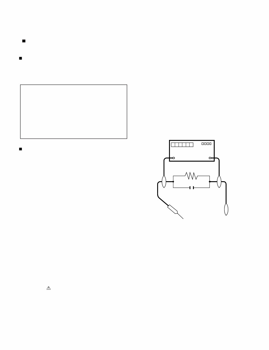
LC-40/46/52/60LE835U/830U/832U/LC-60LE831U i LC-40LE830U Service Manual SAFETY PRECAUTION IMPORTANT SERVICE SAFETY PRECAUTION WARNING 1. For continued safety, no modification of any circuit should be attempted. 2. Disconnect AC power before servicing. BEFORE RETURNING THE RECEIVER (Fire & Shock Hazard) Before returning the receiver to the user, perform the following safety checks: 3. Inspect all lead dress to make certain that leads are not pinched, and check that hardware is not lodged between the chassis and other metal parts in the receiver. 4. Inspect all protective devices such as non-metallic control knobs, insulation materials, cabinet backs, adjustment and compartment covers or shields, isolation resistor-capacitor networks, mechanical insulators, etc. 5. To be sure that no shock hazard exists, check for leakage current in the following manner. • Plug the AC cord directly into a 120 volt AC outlet. • Using two clip leads, connect a 1.5k ohm, 10 watt resistor paral- leled by a 0.15µF capacitor in series with all exposed metal cabinet parts and a known earth ground, such as electrical conduit or elec- trical ground connected to an earth ground. • Use an AC voltmeter having with 5000 ohm per volt, or higher, sen- sitivity or measure the AC voltage drop across the resistor. • Connect the resistor connection to all exposed metal parts having a return to the chassis (antenna, metal cabinet, screw heads, knobs and control shafts, escutcheon, etc.) and measure the AC voltage drop across the resistor. All checks must be repeated with the AC cord plug connection reversed. (If necessary, a nonpolarized adaptor plug must be used only for the purpose of completing these checks.) Any reading of 0.75 Vrms (this corresponds to 0.5 mA rms AC.) or more is excessive and indicates a potential shock hazard which must be corrected before returning the monitor to the owner. /////////////////////////////////////////////////////////////////////////////////////////////////////////////////////////////////////////////////////////////////////////////////////////////////////////////////////////////////////////// SAFETY NOTICE Many electrical and mechanical parts in LCD color television have special safety-related characteristics. These characteristics are often not evident from visual inspection, nor can protection afforded by them be necessarily increased by using replacement components rated for higher voltage, wattage, etc. Replacement parts which have these special safety characteristics are identified in this manual; electrical components having such features are identified by " " and shaded areas in the Replacement Parts List and Schematic Diagrams. For continued protection, replacement parts must be identical to those used in the original circuit. The use of a substitute replacement parts which do not have the same safety characteristics as the factory recommended replacement parts shown in this service manual, may create shock, fire or other hazards. /////////////////////////////////////////////////////////////////////////////////////////////////////////////////////////////////////////////////////////////////////////////////////////////////////////////////////////////////////////// Service work should be performed only by qualified service technicians who are thoroughly familiar with all safety checks and the servicing guidelines which follow: CAUTION : FOR CONTINUED PROTECTION AGAINST A RISK OF FIRE REPLACE ONLY WITH SAME TYPE FUSE. F7001 (250V 5A) DVM AC SCALE 1.5k ohm 10W TO EXPOSED METAL PARTS CONNECT TO KNOWN EARTH GROUND 0.15 µF TEST PROBE
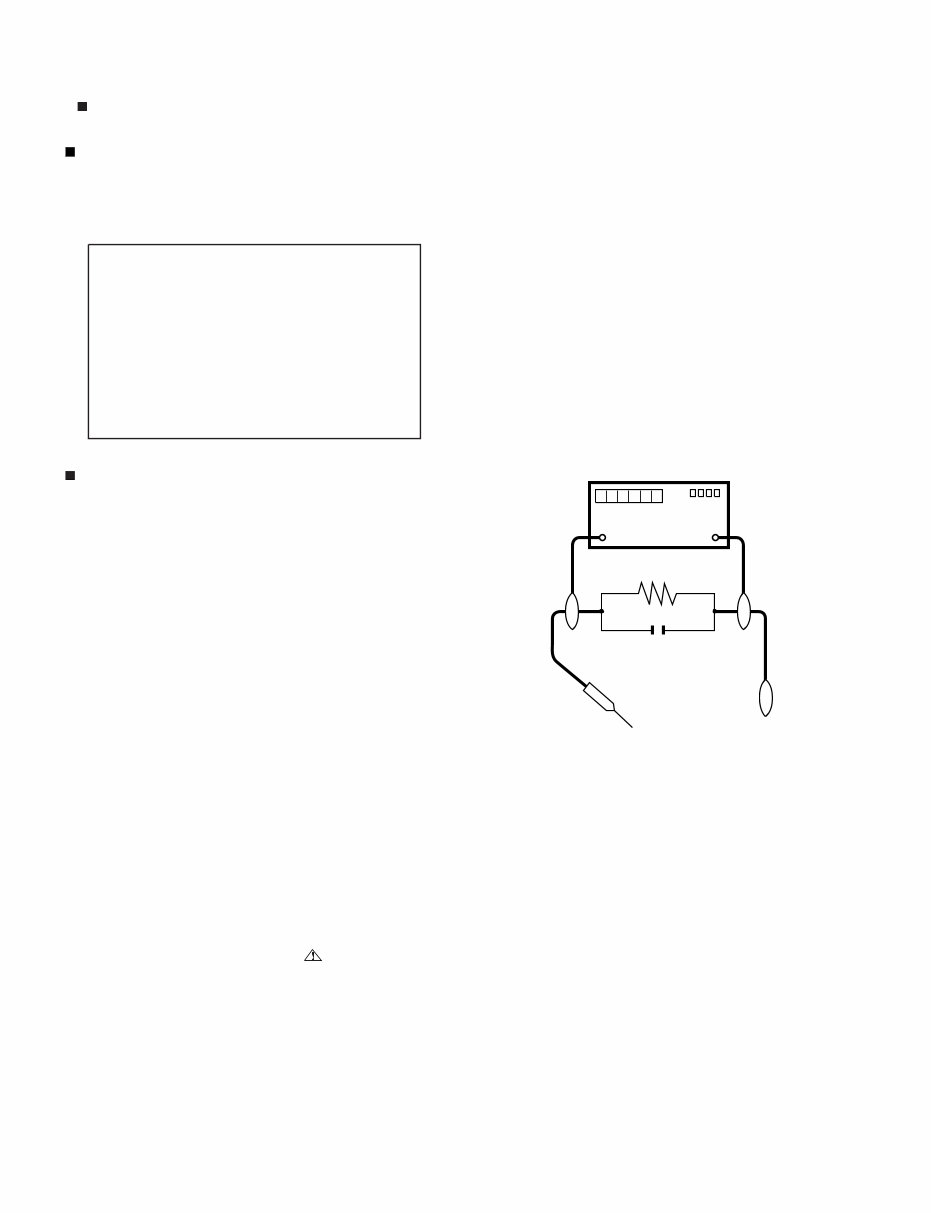
LC-40/46/52/60LE835U/830U/832U/LC-60LE831U ii PRECAUTIONS A PRENDRE LORS DE LA REPARATION De nombreuses pièces, électriques et mécaniques, dans les télévi- seur ACL présentent des caractéristiques spéciales relatives à la sé- curité, qui ne sont souvent pas évidentes à vue. Le degré de protec- tion ne peut pas être nécessairement augmentée en utilisant des pièces de remplacement étalonnées pour haute tension, puissance, etc. Les pièces de remplacement qui présentent ces caractéristiques sont identifiées dans ce manuel; les pièces électriques qui présentent ces particularités sont identifiées par la marque " " et hachurées dans la liste des pièces de remplacement et les diagrammes schématiques. Pour assurer la protection, ces pièces doivent être identiques à celles utilisées dans le circuit d'origine. L'utilisation de pièces qui n'ont pas les mêmes caractéristiques que les pièces recommandées par l'usine, indiquées dans ce manuel, peut provoquer des électrocutions, incen- dies, radiations X ou autres accidents. AVERTISSEMENT 1. 2. 3. 4. 5. • • • • ///////////////////////////////////////////////////////////////////////////////////////////////////////////////////////////////////////////////////////////////////////////////////////////////////////////////////////////////////////////// ///////////////////////////////////////////////////////////////////////////////////////////////////////////////////////////////////////////////////////////////////////////////////////////////////////////////////////////////////////////// Ne peut effectuer la réparation qu' un technicien spécialisé qui s'est parfaitement accoutumé à toute vérification de sécurité et aux conseils suivants. N'entreprendre aucune modification de tout circuit. C'est danger- eux. Débrancher le récepteur avant toute réparation. Inspecter tous les faisceaux de câbles pour s'assurer que les fils ne soient pas pincés ou qu'un outil ne soit pas placé entre le châs- sis et les autres pièces métalliques du récepteur. Inspecter tous les dispositifs de protection comme les boutons de commande non-métalliques, les isolants, le dos du coffret, les cou- vercles ou blindages de réglage et de compartiment, les réseaux de résistancecapacité, les isolateurs mécaniques, etc. S'assurer qu'il n'y ait pas de danger d'électrocution en vérifiant la fuite de courant, de la facon suivante: Brancher le cordon d'alimentation directem-ent à une prise de cou- rant de 120V. (Ne pas utiliser de transformateur d'isolation pour cet essai). A l'aide de deux fils à pinces, brancher une résistance de 1.5 kΩ 10 watts en parallèle avec un condensateur de 0.15µF en série avec toutes les pièces métalliques exposées du coffret et une terre connue comme une conduite électrique ou une prise de terre branchée à la terre. Utiliser un voltmètre CA d'une sensibilité d'au moins 5000Ω/V pour mesurer la chute de tension en travers de la résistance. Toucher avec la sonde d'essai les pièces métalliques exposées qui présentent une voie de retour au châssis (antenne, coffret métalli- que, tête des vis, arbres de commande et des boutons, écusson, etc.) et mesurer la chute de tension CA en-travers de la résistance. Toutes les vérifications doivent être refaites après avoir inversé la fiche du cordon d'alimentation. (Si nécessaire, une prise d'adpatation non polarisée peut être utilisée dans le but de termin- er ces vérifications.) La tension de pointe mesurèe ne doit pas dépasser 0.75V (corre- spondante au courant CA de pointe de 0.5mA). Dans le cas contraire, il y a une possibilité de choc électrique qui doit être supprimée avant de rendre le récepteur au client. PRECAUTION: POUR LA PROTECTION CON- TINUE CONTRE LES RISQUES D'INCENDIE, REMPLACER LE FUSIBLE VERIFICATIONS CONTRE L'INCEN-DIE ET LE CHOC ELECTRIQUE Avant de rendre le récepteur à l'utilisateur, effectuer les vérifica- tions suivantes. DVM ECHELLE CA 1.5k ohm 10W 0.15 µF SONDE D'ESSAI AUX PIECES METALLIQUES EXPOSEES BRANCHER A UNE TERRE CONNUE AVIS POUR LA SECURITE F7001 (250V 5A)
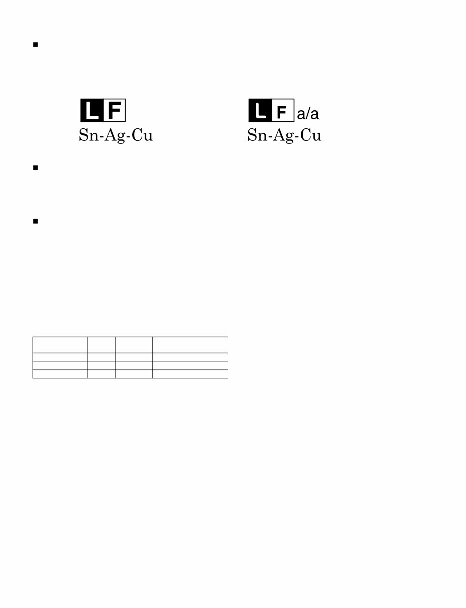
LC-40/46/52/60LE835U/830U/832U/LC-60LE831U iii PRECAUTIONS FOR USING LEAD-FREE SOLDER Employing lead-free solder • “PWBs” of this model employs lead-free solder. The LF symbol indicates lead-free solder, and is attached on the PWBs and service manuals. The alphabetical character following LF shows the type of lead-free solder. Example: Using lead-free wire solder • When fixing the PWB soldered with the lead-free solder, apply lead-free wire solder. Repairing with conventional lead wire solder may cause dam- age or accident due to cracks. As the melting point of lead-free solder (Sn-Ag-Cu) is higher than the lead wire solder by 40 °C, we recommend you to use a dedicated soldering bit, if you are not familiar with how to obtain lead-free wire solder or soldering bit, contact our service station or service branch in your area. Soldering • As the melting point of lead-free solder (Sn-Ag-Cu) is about 220 °C which is higher than the conventional lead solder by 40 °C, and as it has poor solder wettability, you may be apt to keep the soldering bit in contact with the PWB for extended period of time. However, Since the land may be peeled off or the maximum heat-resistance temperature of parts may be exceeded, remove the bit from the PWB as soon as you confirm the steady soldering condition. Lead-free solder contains more tin, and the end of the soldering bit may be easily corroded. Make sure to turn on and off the power of the bit as required. If a different type of solder stays on the tip of the soldering bit, it is alloyed with lead-free solder. Clean the bit after every use of it. When the tip of the soldering bit is blackened during use, file it with steel wool or fine sandpaper. • Be careful when replacing parts with polarity indication on the PWB silk. Lead-free wire solder for servicing Indicates lead-free solder of tin, silver and copper. Indicates lead-free solder of tin, silver and copper. PARTS CODE PRICE RANK PART DELIVERY DESCRIPTION ZHNDAi123250E BL J φ0.3mm 250g (1roll) ZHNDAi126500E BK J φ0.6mm 500g (1roll) ZHNDAi12801KE BM J φ1.0mm 1kg (1roll)
LC-40/46/52/60LE835U/830U/832U/LC-60LE831U iv LC-40LE830U Service Manual OUTLINE MAJOR SERVICE PARTS PWB Unit NOTE: *1 Replace MAIN PWB Units (DKEYMF733FM**) in case of IC8401, IC3303 or IC8455 failure. *2 Touch Sensor Unit reuse will be impossible, once it is stuck on front Cabinet and exfoliates. OTHER Unit IC For Exclusive Use Of The Service Ref No. Parts No. Description N DKEYMF733FM16 MAIN Unit (LC-40LE835U) N DKEYMF733FM14 MAIN Unit (LC-46LE835U) N DKEYMF733FM13 MAIN Unit (LC-52LE835U) N DKEYMF733FM12 MAIN Unit (LC-60LE835U) N DKEYMF733FM04 MAIN Unit (LC-40LE830U) N DKEYMF733FM03 MAIN Unit (LC-46LE830U) N DKEYMF733FM02 MAIN Unit (LC-52LE830U) N DKEYMF733FM01 MAIN Unit (LC-60LE830U) N DKEYMF733FM18 MAIN Unit (LC-60LE831U) N DKEYMF733FM10 MAIN Unit (LC-40LE832U) N DKEYMF733FM08 MAIN Unit (LC-46LE832U) N DKEYMF733FM07 MAIN Unit (LC-52LE832U) N DKEYMF733FM06 MAIN Unit (LC-60LE832U) N DUNTKF494FM01 R/C, Operation Unit N DUNTKF770FM03 ICON Unit (LC-40/46/52/60LE835U) N DUNTKF770FM02 ICON Unit (LC-40/46/52/60LE830U/832U/LC-60LE831U) N RUNTKA810WJQZ WiFi Unit N RUNTKA811WJQZ Touch Sensor Unit (LC-40/46/52/60LE835U) N RUNTKA812WJQZ Touch Sensor Unit (LC-40/46/52/60LE830U/832U/LC-60LE831U) N RUNTKA819WJQZ IR Emitter Unit (LC-40/46/52/60LE835U Only) N RUNTKA786WJQZ POWER/LED Drive Unit (LC-40LE835U/830U/832U) N RUNTKA790WJQZ POWER/LED Drive Unit (LC-46LE835U/830U/832U) N RUNTKA794WJQZ POWER/LED Drive Unit (LC-52LE835U/830U/832U) N RUNTKA798WJQZ POWER/LED Drive Unit (LC-60LE835U/830U/831U/832U) N RUNTK4909TPZS LCD Control Unit (LC-40LE835U) N RUNTK4909TPZW LCD Control Unit (LC-46LE835U) N RUNTK4909TPZF LCD Control Unit (LC-52LE835U) N RUNTK4909TPZA LCD Control Unit (LC-60LE835U) N RUNTK4910TPZE LCD Control Unit (LC-40LE830U/832U) N RUNTK4910TPZC LCD Control Unit (LC-46LE830U/832U) N RUNTK4910TPZB LCD Control Unit (LC-52LE830U/832U) N RUNTK4910TPZZ LCD Control Unit (LC-60LE830U/831U/832U) Ref No. Parts No. Description N R1LK400D3GW50Z 40" LCD Panel Module Unit (LK400D3GW50Z) (LC-40LE835U) N R1LK460D3GW40Z 46" LCD Panel Module Unit (LK460D3GW40Z) (LC-46LE835U) N R1LK520D3GW40Z 52" LCD Panel Module Unit (LK520D3GW40Z) (LC-52LE835U) N R1LK600D3GW40Z 60" LCD Panel Module Unit (LK600D3GW40Z) (LC-60LE835U) N R1LK400D3GW80Z 40" LCD Panel Module Unit (LK400D3GW80Z) (LC-40LE830U/832U) N R1LK460D3GW80Z 46" LCD Panel Module Unit (LK460D3GW80Z) (LC-46LE830U/832U) N R1LK520D3GW80Z 52" LCD Panel Module Unit (LK520D3GW80Z) (LC-52LE830U/832U) N R1LK600D3GW30Z 60" LCD Panel Module Unit (LK600D3GW30Z) (LC-60LE830U/831U/832U) Ref No. Parts No. Description Q'ty IC2001 RH-iXD241WJN1Q IC R5F21368CNFP (Monitor Microcomputer) 1
LC-40/46/52/60LE835U/830U/832U/LC-60LE831U v Service Jigs Ref No. Parts No. Description Q'ty N QCNW-C222WJQZ Connecting Cord L=1000mm 80pin LCD Control Unit to LCD Panel Unit 2 N QCNW-L214WJQZ Connecting Cord L=1000mm 64pin LCD Control Unit to LCD Panel Unit (LC-40/46/52/60LE835U Only) 2 N QCNW-F676WJQZ Connecting Cord L=1000mm 41pin Main to LCD Control Unit (LW) 1 N QCNW-G405WJQZ Connecting Cord L=1000mm 4pin Main to LCD Control Unit (PL) 1 N QCNW-L795WJQZ Connecting Cord L=1000mm 24pin Main to POWER/LED Drive Unit (PD) 1
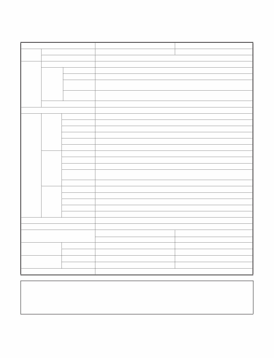
LC-40/46/52/60LE835U/830U/832U/LC-60LE831U 1 – 1 LC-40LE830U Service Manual CHAPTER 1. SPECIFICATIONS [1] SPECIFICATIONS (LC-40/46LE835U/830U/832U) Item Model: LC-40LE835U/830U/832U Model: LC-46LE835U/830U/832U LCD panel Size 40" Class (40" Diagonal) 46" Class (45 63 / 64 " Diagonal) Resolution 2,073,600 pixels (1,920 x 1,080) TV Function TV-standard (CCIR) American TV Standard ATSC/NTSC System Receiving Channel VHF/UHF VHF 2-13ch, UHF 14-69ch CATV 1-135ch (non-scrambled channel only) Digital Terrestrial Broadcast (8VSB) 2-69ch Digital cable *1 (64/256 QAM) 1-135ch (non-scrambled channel only) Audio multiplex BTSC System Audio out 10W x 2 + 15 W (WF) Terminals Back panel vertical inputs HDMI 1 HDMI in with HDCP, Audio in (Ø 3.5 mm stereo jack) HDMI 2 HDMI in with HDCP HDMI 3 HDMI in with HDCP HDMI 4 HDMI in with HDCP AUDIO OUT Audio out (Ø 3.5 mm stereo jack) USB 1 Photo/Music/Video mode, Software update Back panel surface inputs COMPONENT COMPONENT in VIDEO 1 AV in VIDEO 2 AV in PC IN ANALOG RGB (PC) in (15-pin mini D-sub female connector), Audio in (Ø 3.5 mm stereo jack) RS-232C 9-pin D-sub male connector Back panel horizontal inputs ANT/CABLE 75 Ω Unbalance, F Type x 1 for Analog (VHF/UHF/CATV) and Digital (AIR/CABLE) AUDIO IN Audio in (Ø 3.5 mm stereo jack) DIGITAL AUDIO OUTPUT Optical Digital audio output x 1 (PCM/Dolby Digital) ETHERNET Network connector USB 2 Photo/Music/Video mode, Software update OSD language English/French/Spanish Power Requirement AC 120 V, 60 Hz Power Consumption 120 W (0.1 W Standby with AC 120 V) (LE835U) 150 W (0.1 W Standby with AC 120 V) (LE835U) 118 W (0.1 W Standby with AC 120 V) (LE830U/832U) 142 W (0.1 W Standby with AC 120 V) (LE830U/832U) Weight TV + stand 36.4 lbs./16.5 kg 50.7 lbs./23.0 kg TV only 29.8 lbs./13.5 kg 41.9 lbs./19.0 kg Dimension *2 (W x H x D) TV + stand 36 15 / 16 x 25 3 / 64 x 10 25 / 64 inch 42 13 / 64 x 28 x 11 35 / 64 inch TV only 36 15 / 16 x 23 5 / 32 x1 5 / 8 inch 42 13 / 64 x 26 7 / 64 x1 5 / 8 inch Operating temperature +32°F to +104°F (0°C to +40°C) Cautions regarding use in high and low temperature environments When the unit is used in a low temperature space (e.g. room, office), the picture may leave trails or appear slightly delayed. This is not a malfunction, and the unit will recover when the temperature returns to normal. Do not leave the unit in a hot or cold location. Also, do not leave the unit in a location exposed to direct sunlight or near a heater, as this may cause the cabinet to deform and the front panel to malfunction. Storage temperature: -4°F to +140°F (-20°C to +60°C) • •
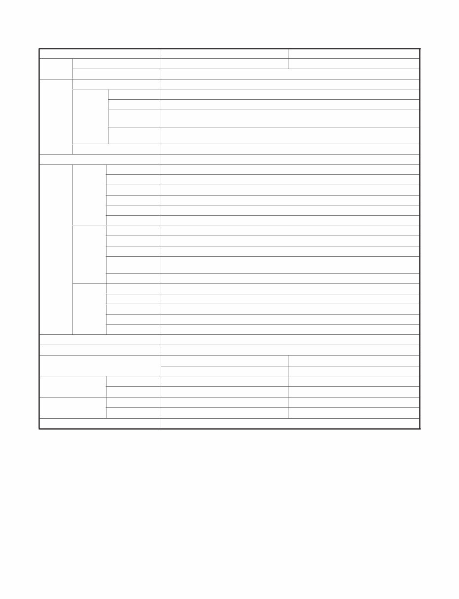
LC-40/46/52/60LE835U/830U/832U/LC-60LE831U 1 – 2 [2] SPECIFICATIONS (LC-52/60LE835U/830U/832U/LC-60LE831U) Item Model: LC-52LE835U/830U/832U Model: LC-60LE835U/830U/831U/832U LCD panel Size 52" Class (52 1 / 32 " Diagonal) 60" Class (60 1 / 32 " Diagonal) Resolution 2,073,600 pixels (1,920 x 1,080) TV Function TV-standard (CCIR) American TV Standard ATSC/NTSC System Receiving Channel VHF/UHF VHF 2-13ch, UHF 14-69ch CATV 1-135ch (non-scrambled channel only) Digital Terrestrial Broadcast (8VSB) 2-69ch Digital cable *1 (64/256 QAM) 1-135ch (non-scrambled channel only) Audio multiplex BTSC System Audio out 10W x 2 + 15 W (WF) Terminals Back panel vertical inputs HDMI 1 HDMI in with HDCP, Audio in (Ø 3.5 mm stereo jack) HDMI 2 HDMI in with HDCP HDMI 3 HDMI in with HDCP HDMI 4 HDMI in with HDCP AUDIO OUT Audio out (Ø 3.5 mm stereo jack) USB 1 Photo/Music/Video mode, Software update Back panel surface inputs COMPONENT COMPONENT in VIDEO 1 AV in VIDEO 2 AV in PC IN ANALOG RGB (PC) in (15-pin mini D-sub female connector), Audio in (Ø 3.5 mm stereo jack) RS-232C 9-pin D-sub male connector Back panel horizontal inputs ANT/CABLE 75Ω Unbalance, F Type x 1 for Analog (VHF/UHF/CATV) and Digital (AIR/CABLE) AUDIO IN Audio in (Ø 3.5 mm stereo jack) DIGITAL AUDIO OUTPUT Optical Digital audio output x 1 (PCM/Dolby Digital) ETHERNET Network connector USB 2 Photo/Music/Video mode, Software update OSD language English/French/Spanish Power Requirement AC 120 V, 60 Hz Power Consumption 170 W (0.1 W Standby with AC 120 V) (LE835U) 220 W (0.1 W Standby with AC 120 V) (LE835U) 162 W (0.1 W Standby with AC 120 V) (LE830U/832U) 213 W (0.1 W Standby with AC 120 V) (LE830U/831U/832U) Weight TV + stand 61.7 lbs./28.0 kg 83.8 lbs./38.0 kg TV only 52.9 lbs./24.0 kg 68.3 lbs./31.0 kg Dimension *2 (W x H x D) TV + stand 47 31 / 64 x 30 63 / 64 x 11 35 / 64 inch 54 29 / 64 x 34 31 / 32 x 14 27 / 64 inch TV only 47 31 / 64 x 29 1 / 16 x1 5 / 8 inch 54 29 / 64 x 33 1 / 32 x1 5 / 8 inch Operating temperature +32°F to +104°F (0°C to +40°C) *1 Emergency alert messages via Cable are unreceivable. *2 The dimensional drawings are shown on the inside back cover. The dimensions include projecting parts. • As part of policy of continuous improvement, SHARP reserves the right to make design and specification changes for product improvement without prior notice. The performance specification figures indicated are nominal values of production units. There may be some deviations from these values in individual units.
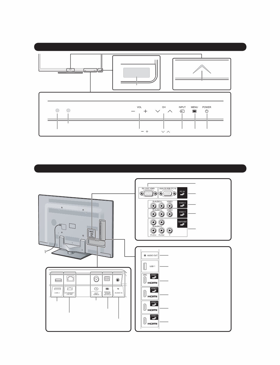
LC-40/46/52/60LE835U/830U/832U/LC-60LE831U 2 – 1 LC-40LE830U Service Manual CHAPTER 2. OPERATION MANUAL [1] Parts Name TV (Front) 3D infrared emitter *1 3D Model Only Center Icon illumination POWER *3 INPUT VOL / MENU Remote control sensor OPC sensor *2 CH / *1 This panel emits the infrared signal towards the 3D Glasses you wear when you view 3D images. Do not place anything between the 3D infrared emitter on the TV and the infrared receiver on the 3D Glasses. (3D Model: LC-40/46/52/60LE835U Only) *2 OPC: Optical Picture Control. *3 for using the touch sensor panel. TV (Rear) RS-232C terminal Antenna/ Cable in COMPONENT terminals DIGITAL AUDIO OUTPUT terminal HDMI 3 terminal HDMI 4 terminal HDMI 1 terminal ARC: Audio Return Channel VIDEO 2 terminals VIDEO 1 terminals AUDIO OUT terminal USB 1 terminal USB 2 terminal ETHERNET terminal HDMI 2 terminal PC IN terminal *1 *1 *1 AUDIO IN terminal (shared for PC IN and HDMI 1) *2 *1 for external equipment connection. *2 for details on the Audio Select function.
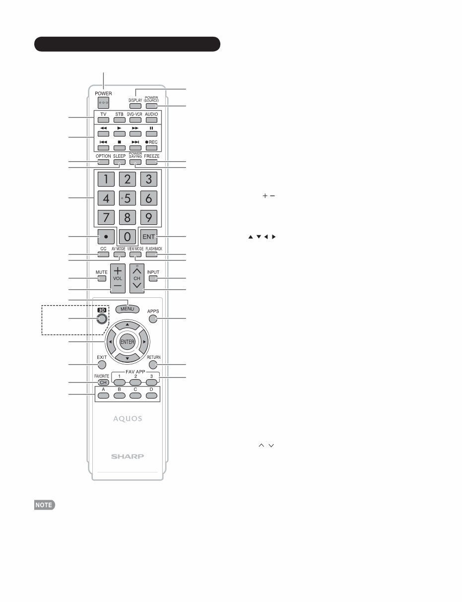
LC-40/46/52/60LE835U/830U/832U/LC-60LE831U 2 – 2 1 18 19 20 21 4 3 2 5 23 24 8 7 6 9 25 26 28 29 15 14 13 12 11 10 16 17 27 22 1 POWER: Switch the TV power on or enter standby. 2 TV, STB, DVD•VCR, AUDIO: Switches the remote control for TV, STB, DVD, BD, VCR and AUDIO operation. * To enter the code registration mode, you need to press an appropriate button (STB, DVD•VCR or AUDIO) and DISPLAY at the same time. 3 External equipment operational buttons: Operate the external equipment. 4 OPTION: Display the Link Operation Menu screen. This button will function only when AQUOS LINK is used. 5 SLEEP: Set the sleep timer. 6 0–9: Set the channel. 7 •(DOT): 8 CC: Display captions from a closed-caption source. 9 AV MODE: Select an audio or video setting. 10 MUTE: Mute the sound. 11 VOL / : Set the volume. 12 MENU: Display the menu screen. 13 3D: Select between 3D and 2D image viewing. (3D Model : LC-40/46/52/60LE835U Only) 14 / / / ,ENTER: Select a desired item on the screen. 15 EXIT: Turn off the menu screen. 16 FAVORITE CH: Set the favorite channels. 17 A, B, C, D: Select 4 preset favorite channels in 4 different categories. While watching, you can toggle the selected channels by pressing A, B, C and D. 18 DISPLAY: Display the channel information. 19 POWER (SOURCE): Turns the power of the external equipment on and off. 20 FREEZE: Set the still image. Press again to return to normal screen. 21 POWER SAVING: Select Power Saving settings. 22 ENT: Jumps to a channel after selecting with the 0–9 buttons. 23 FLASHBACK: Return to the previous channel or external input mode. 24 VIEW MODE: Select the screen size. 25 INPUT: Select a TV input source. (TV, HDMI1, HDMI2, HDMI3, HDMI4, COMPONENT, VIDEO1, VIDEO2, PC IN, Home Network (DLNA), USB) 26 CH / : Select the channel. 27 APPS: Display the application window. 28 RETURN: Return to the previous menu screen. 29 FAV APP 1, 2, 3: You can assign your favorite applications to these buttons. Remote Control Unit • When using the remote control unit, point it at the TV. 3D Model Only
Are you experiencing issues with your Sharp LCD LED Television? Instead of costly repairs or replacements, consider troubleshooting and fixing it yourself with the help of this comprehensive service and repair manual. This manual is utilized by certified Sharp technicians and contains detailed instructions for both professional mechanics and DIY enthusiasts.
Learn about safety and operations
Disassembly and assembly procedures
Adjustment procedures
Troubleshooting techniques
Wiring diagrams
Block diagrams
Exploded view of the device
Parts list catalog
The manual features high-resolution colored pictures and step-by-step guidance, ensuring you can effectively service and repair your LCD LED TV. It is an official manual, not a scanned or bootlegged copy, and provides instant access upon payment without any shipping delays. The language is English, and it is available in a format suitable for both Windows and MAC platforms, spanning across 110 pages.