

LG 60PM6700 UB Service Manual and Repair Guide
What's Included?
Fast Download Speeds
Online & Offline Access
Access PDF Contents & Bookmarks
Full Search Facility
Print one or all pages of your manual
North/Latin America http://aic.lgservice.com
Europe/Africa http://eic.lgservice.com
Asia/Oceania http://biz.lgservice.com
Internal Use Only
Printed in Korea P/NO : MFL67461803 (1205-REV01)
PLASMA TV
SERVICE MANUAL
CHASSIS : PU22A
MODEL : 60PM6700 60PM6700-UB
CAUTION
BEFORE SERVICING THE CHASSIS,
READ THE SAFETY PRECAUTIONS IN THIS MANUAL.

- 2 -
LGE Internal Use Only Copyright © LG Electronics. Inc. All rights reserved.
Only for training and service purposes
CONTENTS
CONTENTS .............................................................................................. 2
SAFETY PRECAUTIONS ........................................................................ 3
SPECIFICATION ....................................................................................... 4
ADJUSTMENT INSTRUCTION ................................................................ 5
BLOCK DIAGRAM.................................................................................. 12
EXPLODED VIEW .................................................................................. 13
SCHEMATIC CIRCUIT DIAGRAM ..............................................................
- 3 -
LGE Internal Use Only Copyright © LG Electronics. Inc. All rights reserved.
Only for training and service purposes
Many electrical and mechanical parts in this chassis have special safety-related characteristics. These parts are identified by in the
Schematic Diagram and Exploded View.
It is essential that these special safety parts should be replaced with the same components as recommended in this manual to prevent
Shock, Fire, or other Hazards.
Do not modify the original design without permission of manufacturer.
General Guidance
An isolation Transformer should always be used during the
servicing of a receiver whose chassis is not isolated from the AC
power line. Use a transformer of adequate power rating as this
protects the technician from accidents resulting in personal injury
from electrical shocks.
It will also protect the receiver and it's components from being
damaged by accidental shorts of the circuitry that may be
inadvertently introduced during the service operation.
If any fuse (or Fusible Resistor) in this TV receiver is blown,
replace it with the specified.
When replacing a high wattage resistor (Oxide Metal Film Resistor,
over 1 W), keep the resistor 10 mm away from PCB.
Keep wires away from high voltage or high temperature parts.
Before returning the receiver to the customer,
always perform an AC leakage current check on the exposed
metallic parts of the cabinet, such as antennas, terminals, etc., to
be sure the set is safe to operate without damage of electrical
shock.
Leakage Current Cold Check(Antenna Cold Check)
With the instrument AC plug removed from AC source, connect an
electrical jumper across the two AC plug prongs. Place the AC
switch in the on position, connect one lead of ohm-meter to the AC
plug prongs tied together and touch other ohm-meter lead in turn to
each exposed metallic parts such as antenna terminals, phone
jacks, etc.
If the exposed metallic part has a return path to the chassis, the
measured resistance should be between 1 MΩ and 5.2 MΩ.
When the exposed metal has no return path to the chassis the
reading must be infinite.
An other abnormality exists that must be corrected before the
receiver is returned to the customer.
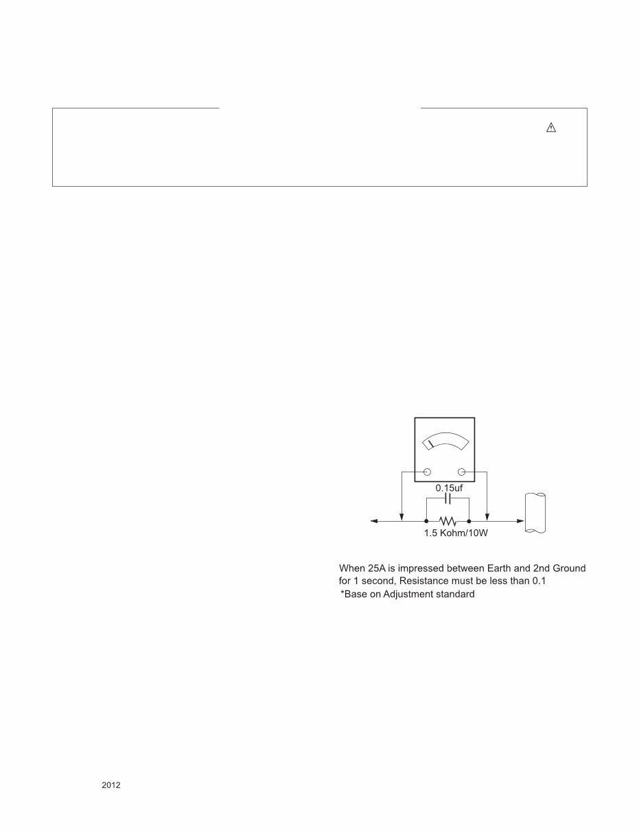
Leakage Current Hot Check (See below Figure)
Plug the AC cord directly into the AC outlet.
Do not use a line Isolation Transformer during this check.
Connect 1.5 K / 10 watt resistor in parallel with a 0.15 uF capacitor
between a known good earth ground (Water Pipe, Conduit, etc.)
and the exposed metallic parts.
Measure the AC voltage across the resistor using AC voltmeter
with 1000 ohms/volt or more sensitivity.
Reverse plug the AC cord into the AC outlet and repeat AC voltage
measurements for each exposed metallic part. Any voltage
measured must not exceed 0.75 volt RMS which is corresponds to
0.5 mA.
In case any measurement is out of the limits specified, there is
possibility of shock hazard and the set must be checked and
repaired before it is returned to the customer.
Leakage Current Hot Check circuit
IMPORTANT SAFETY NOTICE
To Instrument's
exposed
METALLIC PARTS
Good Earth Ground
such as WATER PIPE,
CONDUIT etc.
AC Volt-meter
SAFETY PRECAUTIONS
- 4 -
LGE Internal Use Only Copyright © LG Electronics. Inc. All rights reserved.
Only for training and service purposes
SPECIFICATION
NOTE : Specifications and others are subject to change without notice for improvement.
1. Application range
This spec sheet is applied all of the PDP TV with PU22A chassis.
2. Requirement for Test
Each part is tested as below without special appointment.
(1) Temperature: 25 °C ± 5 °C(77 °F ± 9 °F), CST: 40 °C ± 5 °C
(2) Relative Humidity: 65 % ± 10 %
(3) Power Voltage
: Standard input voltage (AC 100-240 V~, 50/60 Hz)
* Standard Voltage of each products is marked by models.
(4) Specification and performance of each parts are followed each drawing and specification by part number in accordance with
BOM.
(5) The receiver must be operated for about 5 minutes prior to the adjustment.
3. Test method
(1) Performance: LGE TV test method followed
(2) Demanded other specification
- Safety : CE, IEC specification
- EMC : CE, IEC
4. Model General Specification
No Item Specification Remark
1 Receiving System 1) ATSC / NTSC-M
2 Available Channel 1) VHF : 02~13
2) UHF : 14~69
3) DTV : 02-69
4) CATV : 01~135
5) CADTV : 01~135
3 Input Voltage 1) AC 100 ~ 240V 50/60Hz N.America Mark : 110V, 60Hz
4 Market NORTH AMERICA
5 Screen Size 42 inch HD(1024 × 768) 42PM4700-UA/UB
50 inch HD(1024 × 768) 50PM4700-UA/UB
50 inch FHD(1920 × 1080) 50PM6700-UB/UD, 50PM6900-UE, 50PM9700-UA
60 inch FHD(1920 × 1080) 60PM6700-UB/UD, 60PM6900-UE, 60PM9700-UA
6 Aspect Ratio 16:9
7 Tuning System FS
8 Module PDP42T4#### (1024 × 768) 42PM4700-UA/UB
PDP50T4#### (1024 × 768) 50PM4700-UA/UB
PDP50R4#### (1920 × 1080) 50PM6700-UB/UD, 50PM6900-UE, 50PM9700-UA
PDP60R4#### (1920 × 1080) 60PM6700-UB/UD, 60PM6900-UE, 60PM9700-UA
9 Operating Environment 1) Temp : 0 ~ 40 deg
2) Humidity : ~ 80 %
10 Storage Environment 1) Temp : -20 ~ 60 deg
2) Humidity : ~ 85 %
- 5 -
LGE Internal Use Only Copyright © LG Electronics. Inc. All rights reserved.
Only for training and service purposes
ADJUSTMENT INSTRUCTION
1. Application Range
This spec. sheet applies to PU22A chassis applied PDP TV all
models manufactured in TV factory.
2. Specification
(1) Because this is not a hot chassis, it is not necessary to
use an isolation transformer. However, the use of isolation
transformer will help protect test instrument.
(2) Adjustment must be done in the correct order.
(3) The adjustment must be performed in the circumstance of
25 °C ± 5 °C of temperature and 65±10% of relative
humidity if there is no specific designation.
(4) The input voltage of the receiver must keep 100~240V,
50/60Hz.
(5) The receiver must be operated for about 5 minutes prior to
the adjustment when module is in the circumstance of over
15 °C
- In case of keeping module is in the circumstance of 0°C, it
should be placed in the circumstance of above 15°C for 2
hours
- In case of keeping module is in the circumstance of below
-20 °C, it should be placed in the circumstance of above 15
°C for 3 hours,.
* Caution : When still image is displayed for a period of 20
minutes or longer (especially where W/B scale is
strong. Digital pattern 13ch and/or Cross hatch
pattern 09ch), there can some afterimage in the black
level area.
3. Adjustment items
3.1. PCB Assembly adjustment
* Caution : Using ‘power on’ button of the control R/C power
on TV
(1) MAC Address, ESN and Wide-vine Key Download
(2) DFT Process
3.2. Set Assembly Adjustment
■ Power PCB Assembly Voltage adjustment (Va,Vs voltage
adjustment)
■ Adjustment of White Balance
■ Serial number download & Model name D/L
■ Checking the Eye-Q Operation
■ LAN port inspection (Ping test)
■ Magic Motion Remote Controller test
■ 3D function test
■ GND and ESD test
3.3. Additional
■ Selection Factory output option
■ S/W Download Guide
4. Board-level adjustment
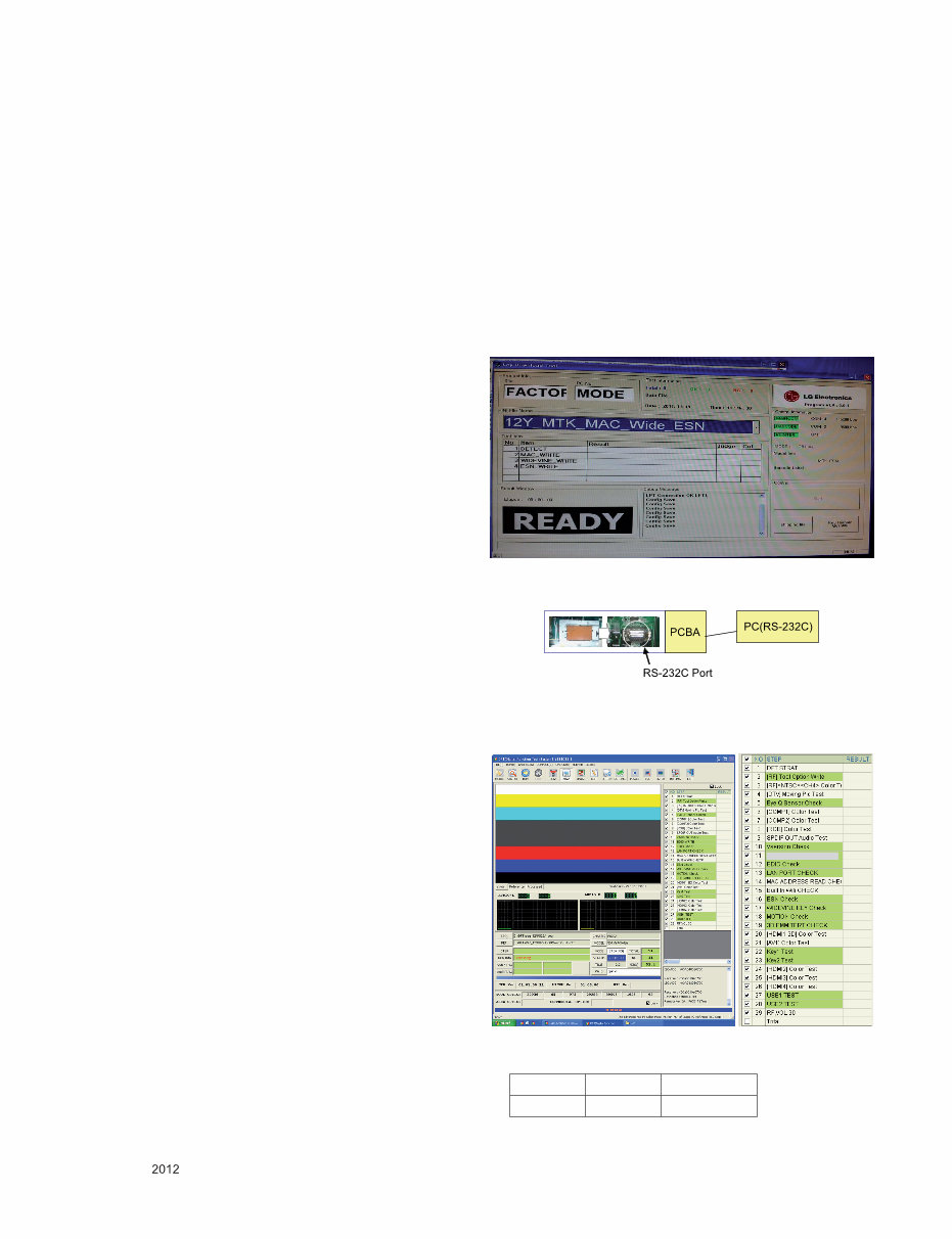
4.1. MAC Address and ESN and Wide-vine
Key Download
* Connect TV SET and PC which download keys Writing
program by RS232C-Cable
(1) Start Program and Click ‘start’ Button to connect TV and
PC.
(2) When download succeed, you can see “OK” on the
screen.
* Each Chassis has it’s own MAC Address/ESN/Wide-vine
key. Please be careful of download.
- RS-232C Port connection
Connect: PCBA Jig-> RS-232C Port== PC-> RS-232C Port
4.2. DFT Process
* Depend on situation, Step can be changed.
* Condition spec
Mode Volume Power Off
RF 0 DC On
- 6 -
LGE Internal Use Only Copyright © LG Electronics. Inc. All rights reserved.
Only for training and service purposes
* ADC Adjustment(Manual)
-> GP4 (PU22A/PB22A/PK22A) Chassis don’t need ADC
adjust process.The ADC value have been OTP process.
but, if you need to adjust ADC manually follow this
method.
■ Using instruments
- Adjustment remocon, 801GF(802B, 802F, 802R) or
MSPG925FA pattern generator
(It can output 480i/1080i horizontal 100% color bar
pattern signal, and its output level must setting 0.7V±0.1V
p-p correctly)
(1) Adjustment method 480i Comp1, Adjust 1080p Comp1/
RGB (Factory adjustment)
(2) ADC 480i Component1 adjustment
(3) Check connection of Component1
(4) MSPG-925FA -> Model: 209, Pattern 65
(5) Set Component 480i mode and 100% Horizontal Color Bar
Pattern(HozTV31Bar), then set TV set to Component1
mode and its screen to “NORMAL”
(6) Check connection both of Component1 and RGB
(7) MSPG-925FA -> Model: 225, Pattern 65
(8) Set Component 1080p mode and 100% Horizontal Color
Bar Pattern(HozTV31Bar), then set TV set to Component1
mode and its screen to “NORMAL”
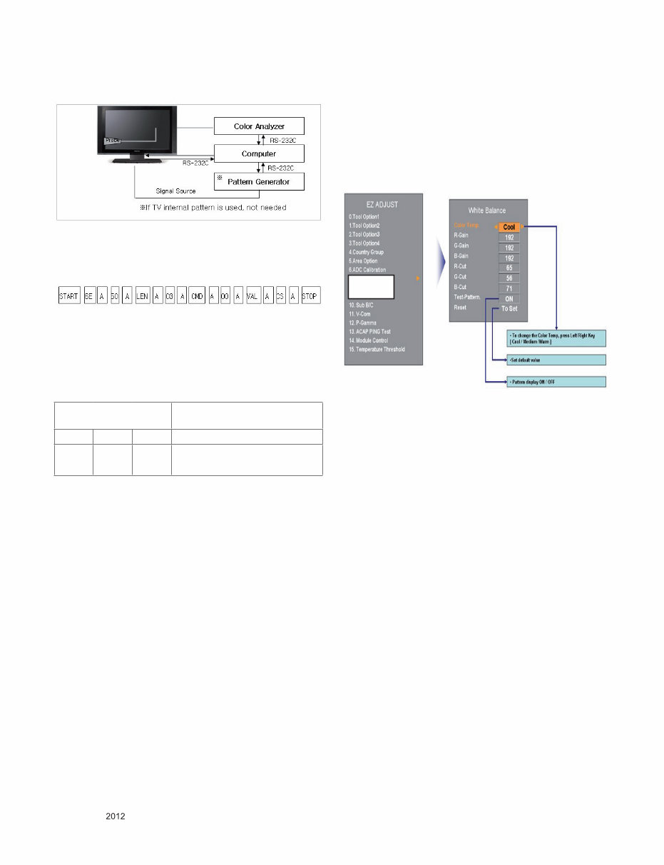
(9) After get each the signal, enter the “EZ ADJUST” status
with pres ADJUST key of Service remocon. After then
select “8. ADC Calibration” with navigator button and press
“Enter”.
(10) After then select “ADC Type” and set value “OTP ->
External” with navigator button.
(11) After then press “Start” button.
(12) You can see “ADC Component1 Success”
(13) Component1 1080p, RGB 1080p Adjust is same method.
(14) Component 1080p Adjustment in Component1 input
mode.
(15) RGB 1080p adjustment in RGB input mode.
(16) If you success RGB 1080p Adjust. You can see “ADC
RGB-DTV Success
4.3. EDID(The Extended Display Identification
Data)/ DDC(Display Data Channel)
- It is a VESA regulation. A PC or a MNT will display an
optimal resolution through information sharing without any
necessity of user input. It is a realization of “Plug and Play”.
-> GP4 (PU22A/PB22A/PK22A) Chassis don’t need EDID
Download process.
Whenever TV power on, the EDID data was written on
inner memory.
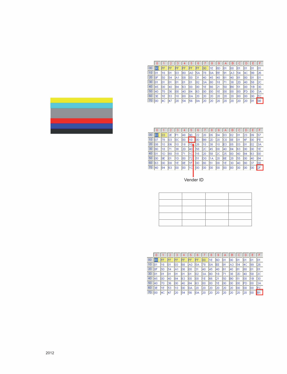
4.3.1. EDID DATA(PCM)_PU22A
■ HDMI [C/S: 98 2F] : For FHD Models
EDID Block 0, Bytes 0-127 [00H-7FH]
Block Type: EDID 1.4
EDID Block 1, Bytes 128-255 [80H-FFH]
Block Type: CEA EDID Timing Extension Version 3
■ RGB [C/S: B1] : For FHD Models
EDID Block 0, Bytes 0-127 [00H-7FH]
Block Type: EDID 1.3
< Adjustment pattern : 480i / 1080p 60Hz Pattern >
Vender ID C/S1 C/S2
HDMI1 10 98 2F
HDMI2 20 98 1F
HDMI3 30 98 0F
HDMI4 40 98 FF
- 7 -
LGE Internal Use Only Copyright © LG Electronics. Inc. All rights reserved.
Only for training and service purposes
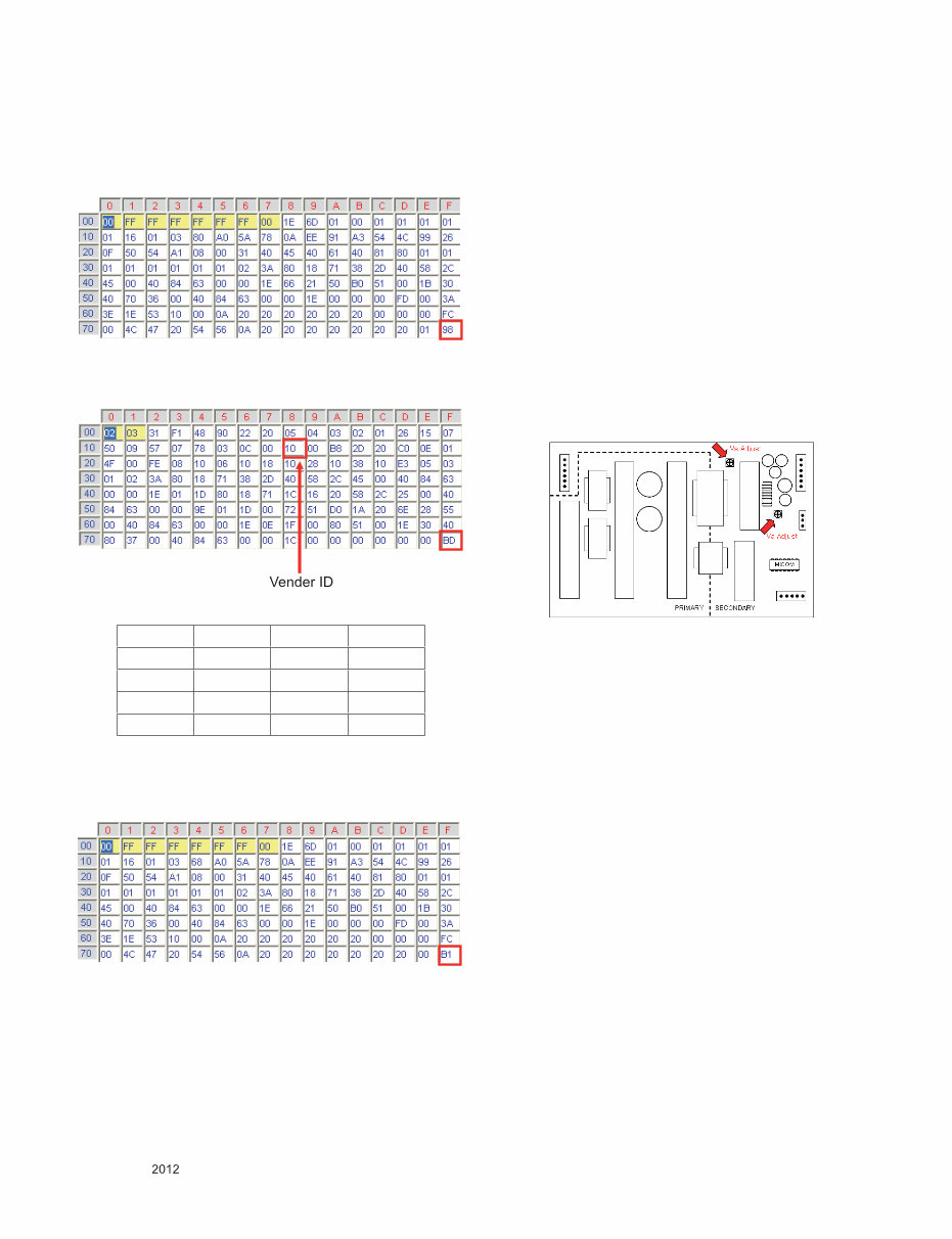
4.3.2. EDID DATA(AC-3)_PU22A
■ HDMI [C/S: 98 BD] : For FHD Models
EDID Block 0, Bytes 0-127 [00H-7FH]
Block Type: EDID 1.3
EDID Block 1, Bytes 128-255 [80H-FFH]
Block Type: CEA EDID Timing Extension Version 3
■ RGB [C/S: B1] : For FHD Models
EDID Block 0, Bytes 0-127 [00H-7FH]
Block Type: EDID 1.3
5. Final Assembly adj.
* Caution : Each PCB assembly must be checked by check
JIG set. (Because power PCB Assembly damages
to PDP Module, especially be careful)
5.1. POWER Supply Unit PCB Ass'y Va/Vs
Voltage adjustment.
* Caution : Both Vs and Va voltage adjustment are necessary.
5.1.1. Model name
: PU22A
5.1.2. Va/Vs Adjustment Procedure
(1) Connect positive(+) terminal of DMM to Vs/Va pin, connect
negative(-) terminal to GND.
(2) Turning ‘Vs/Va Adjust’ and adjust Vs/Va voltages to a value
which is written on a right/top label of a module.
(deviation ; ±0.5V)
* Caution : Each Power Supply Unit PCB assembly must be
checked by check JIG set. (Because power PCB
Ass’y damages to PDP Module, especially be
careful)
* Caution : Set up "RF mode(noise)" before a voltage adjust-
ment.
5.2. White Balance adj.
5.2.1. Overview
■ W/B adj. : Objective & How-it-works
- Objective: To reduce each Panel’s W/B deviation
- How-it-works: When R/G/B gain in the OSD is at 192,
it means the panel is at its Full Dynamic
Range. In order to prevent saturation of
Full Dynamic range and data, one of R/G/B
is fixed at 192, and the other two is lowered
to find the desired value.
5.2.2. Equipment
(1) Color Analyzer : CA-210 (NCG: CH 9 / WCG: CH12 /PDP
Module:CH10)
(2) Adj. Computer (During auto adj., RS-232C protocol is
needed)
(3) Adj. R/C
(4) Video Signal Generator MSPG-925F
720p/216Gray(Model:217, Pattern:78)
→ Only when internal pattern is not available
■ Color Analyzer Matrix should be calibrated using CS-1000
Vender ID C/S1 C/S2
HDMI1 10 98 BD
HDMI2 20 98 AD
HDMI3 30 98 9D
HDMI4 40 98 8D
- 8 -
LGE Internal Use Only Copyright © LG Electronics. Inc. All rights reserved.
Only for training and service purposes
5.2.3. Equipment connection map
5.2.4. Adj. Command (Protocol)
■ Protocol
<Command Format>
- LEN: Number of Data Byte to be send
- CMD: Command
- VAL: FOS Data
- CS: Checksum of sent Data
- A: Acknowledge
Ex) [Send: JA_00_DD] / [Ack: A_00_okDDX]
■ RS-232C Command used during auto-adj.
Ex) wb 00 00 -> Begin white balance auto-adj.
wb 00 10 -> Gain adj.
ja 00 ff -> Adj. data
jb 00 c0
...
...
wb 00 1f -> Gain adj. complete
*(wb 00 20(Start), wb 00 2f(End)) -> Off-set adj.
wb 00 ff -> End white balance auto-adj.
5.2.5. Adj. method
5.2.5.1. Auto adj. method
(1) Set TV in adj. mode using POWER On Key
(2) Zero calibrate probe then place it on the center of the
Display
(3) Connect Cable(RS-232C)
(4) Select mode in adj. Program and begin adj.
(5) When adj. is complete (OK Sign), check adj. status per
mode
(Warm, Medium, Cool)
(6) Remove probe and RS-232C cable to complete adj.
■ Adj. must begin w/ command “wb 00 00”, and end w/“wb
00 ff”and adj. offset if needed.
■ Offset adjust limit value.
Offset Min = 34 (Decimal)
Offset Max = 94 (Decimal)
5.2.5.2. Auto adj. Sequence
- White Balance Adjust Sequence
Start -> Cool_Gain -> Medium_Gain -> Warm_Gain -> End
5.2.5.3. Manual adj. method
Dynamic contrast : off
Dynamic color : off
OPC : Off
Energy saving mode : Off
● Test Equipment: CA-210
- Using PDP color temperature, Color Analyzer (CA-210)
must use CH 10, which Matrix compensated (White, Red,
Green, Blue compensation) with CS-2100. See the
Coordination bellowed one.
● Manual adjustment sequence is like bellowed one.
- Turn to “Ez-Adjust” mode with press ADJ button of service
remocon.
- Select “10.Test Pattern” with CH+/- button and press
enter. Then set will go on Heat-run mode. Over 30
minutes set let on Heat-run mode.
- Let CA-210 to zero calibration and must has gap more
10cm from center of PDP module when adjustment.
- Press “ADJ” button of service remocon and select
“7.White-Balance” in “Ez-Adjust” then press “►” button of
navigation key. (When press “►” button then set will go to
full white mode)
- Adjust at three mode (Cool, Medium, Warm)
- If “cool” mode
Let B-Gain to 192 and R, G, B-Cut to 64 and then control
R, G gain adjustment High Light adjustment.
- If “Medium” and “Warm” mode Let R-Gain to 192 and R,
G, B-Cut to 64 and then control G, B gain adjustment
High Light adjustment.
- All of the three mode
Let R-Gain to 192 and R, G, B-Cut to 64 and then control
G, B gain adjustment High Light adjustment.
- With volume button (+/-) you can adjust.
- After all adjustment finished, with Enter (■ key) turn to
Ez-Adjust mode. Then with ADJ button, exit from
adjustment mode
* Attachment: White Balance adjustment coordination and
color temperature.
RS-232C COMMAND
[CMD ID DATA]
Meaning
wb 00 00 Begin White Balance adj.
wb 00 ff End White Balance adj. (internal
pattern disappears)
9. White Balance
- 9 -
LGE Internal Use Only Copyright © LG Electronics. Inc. All rights reserved.
Only for training and service purposes
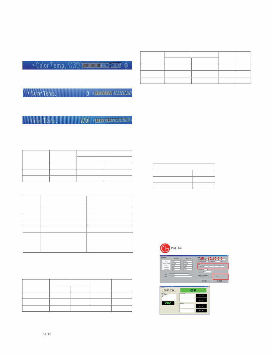
● Using CS-1000 Equipment.
- COOL : T=11000K, ∆uv=0.000, x=0.276 y=0.283
- MEDIUM : T=9300K, ∆uv=0.000, x=0.285 y=0.293
- WARM : T=6500K, ∆uv=0.000, x=0.313 y=0.329
● When tester will measure on Cool condition, adjust W30 on
TV display menu.
● When tester will measure on medium condition, adjust 0 on
TV display menu.
● When tester will measure on warm condition, adjust W30 on
TV display menu.
● Using CA-210 Equipment. (10 CH)
- Contrast value: 216 Gray
- Brightness spec.
5.2.6 Reference
(White Balance adj. coordinate and color temperature)
■ Standard color coordinate and temperature using CS-1000
■ Luminance: Full white 216 Gray
■ Standard color coordinate and temperature using CA-210(CH 10)
- Gain color coordinate
■ Pattern : Full white 216 Gray
5.3. Serial number download & Model name D/L.
(1) Press "Power on" button of a service R/C.(Baud rate :
115200 bps)
(2) Connect RS232-C Signal Cable and start ‘Option Check
Program Ver3.8’
(3) Scan serial Number and press ‘F5’ button.
(4) Check ‘OK’ on program 1) program.
(5) Press ‘In start’ button on SVC R/C, check Serial Number
and Model Name.
5.4. Checking the EYE-Q Operation.
(1) Press the EYE Key on the adjustment remote controller.
(2) Check the Sensor DATA ( It must be under 10) and keep
the data longer than 1.5s
(3) Check ‘OK’
(Sensor DATA 0 ~ 4095, Power Saving Mode 0 ~ 12)
* IF you press IN-STAP Button, change Green Eye-check
OSD.
5.4.1. LAN PORT inspection (PING TEST)
* In this case Network setting is on Manual Setting.
(1) Play the LAN Port Test Program.
(2) connect each other LAN Port Jack.
(3) Play Test (F9) button and confirm OK Message.
(4) remove LAN CABLE
Color
temperature
Test
Equipment
Color Coordination
x y
COOL CA-210 0.276 ± 0.002 0.283 ± 0.002
MEDIUM CA-210 0.285 ± 0.002 0.293 ± 0.002
WARM CA-210 0.313 ± 0.002 0.329 ± 0.002
Item White average
brightness
Brightness uniformity
Min 49 -20
Typ 60
Max +20
Unit cd/m² %
Remark - 100% Window White
Pattern
- 100IRE(255Gray)
- Picture: Vivid(Medium)
- 85IRE(216Gray) 100%
Window White Pattern
- Picture: Vivid(Medium)
Color
temperature
Color Coordination Temp ∆uv
x y
COOL 0.276 0.283 11000K 0.0000
MEDIUM 0.285 0.293 9300K 0.0000
WARM 0.313 0.329 6500K 0.0000
Color
temperature
Color Coordination Temp ∆uv
x y
COOL 0.276 ± 0.002 0.283 ± 0.002 11000K 0.0000
MEDIUM 0.285 ± 0.002 0.293± 0.002 9300K 0.0000
WARM 0.313 ± 0.002 0.329 ± 0.002 6500K 0.0000
Green Eye-Check(Factory Mode)
Sensor Data 9
Power saving mode 1
OK
- 10 -
LGE Internal Use Only Copyright © LG Electronics. Inc. All rights reserved.
Only for training and service purposes
5.5. Magic Motion Remote Controller test
- Required Equipment : RF Remote Controller for test
* You must confirm the battery power of Remote Controller
before test (Recommend that change the battery per every
lot)
(1) Within 50 cm of the TV set, select the wheel ‘Enter’ button
of the controller.
(2) You can check the controller LED on and the cursor on the
TV Screen.
(3) You must remove the pairing with the TV Set by select
‘Mute Key’ on the controller.
(4) Then you can check the cursor on the TV screen is
disappeared and the controller LED off.
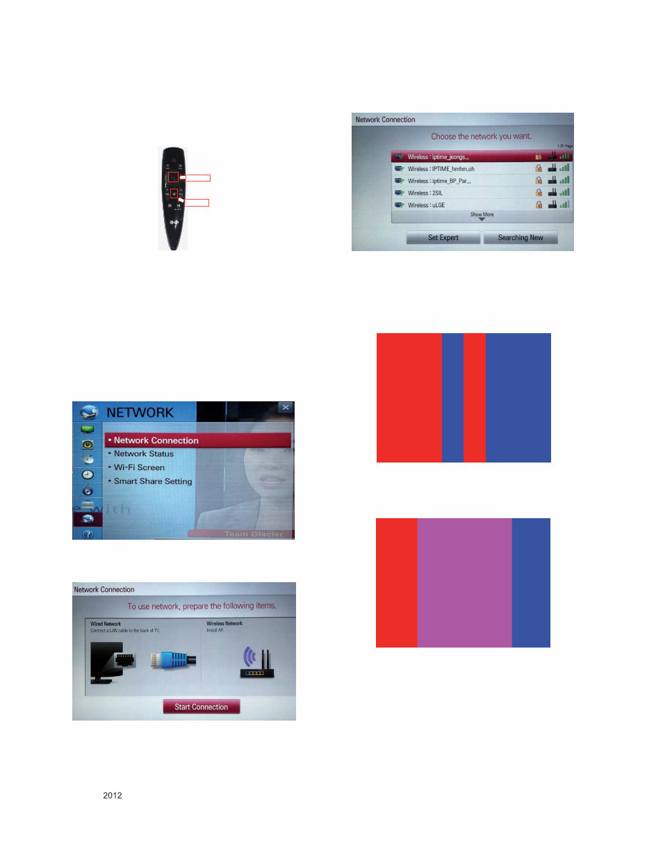
5.6. Wi-Fi Test(Except for PM47*/PM67*)
Step 1) Turn on TV
Step 2) Select ‘Network Connection’ option in Network Menu.
Step 3) Select ‘Start Connection’ Button in ‘Network
Connection’.
Step 4) If the system finds any AP like blow PIC, it is working
well.
5.7. 3D Function Test
(Pattern Generator MSPG-3233, HDMI mode NO. 371 ,
pattern No. 81)
(1) Please input 3D test pattern like below
(2) Enter 3D mode , then select side by side
(If you don’t wear a 3D Glasses, you will see the picture
like below)
<
<
<
<
You're Reading a Preview
What's Included?
Fast Download Speeds
Online & Offline Access
Access PDF Contents & Bookmarks
Full Search Facility
Print one or all pages of your manual
$31.99
Viewed 83 Times Today


Secure transaction
What's Included?
Fast Download Speeds
Online & Offline Access
Access PDF Contents & Bookmarks
Full Search Facility
Print one or all pages of your manual
$31.99
- This official factory service, repair, and workshop manual is essential for troubleshooting and repairing your LG 60PM6700 UB television.
- It covers product safety, servicing precautions, specifications, adjustment instructions, exploded view, troubleshooting methods, block diagram, schematic circuit diagram, and the repair process.
- The manual is in the highest resolution, ensuring great quality when printing the pages you need.
- Instant access after payment, with no shipping fees or waiting on postal delivery, allows you to start repairs within minutes.
- Specifications:
- Language: English
- Format: PDF
- Platform: Windows and MAC
- This comprehensive manual is used by certified LG technicians and maintenance employees, ensuring that your repairs, service, and maintenance jobs are done correctly.


