

Onkyo HT-R510 AV RECEIVER Service Manual
What's Included?
Fast Download Speeds
Online & Offline Access
Access PDF Contents & Bookmarks
Full Search Facility
Print one or all pages of your manual
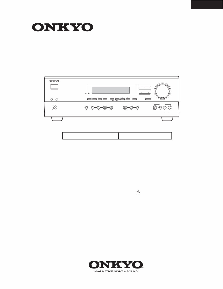
HT-R510
SERVICE MANUAL SERVICE MANUAL
Ref. No. 3778
062003
120V AC, 60Hz
AV RECEIVER
MODEL HT-R510
Black models
BMDD
STANDBY/ON
PHONES
MASTER VOLUME
VIDEO 2 TAPE TUNER CD VIDEO 3 DVD
A B SPEAKERS DIMMER
SURROUND
VIDEO 1
VCR
AUDIO
SELECTOR
DSP
STEREO
STANDB Y
DISPLA Y AUDIO ADJUST SPEAKER ADJUST FM MODE
SUBWOOFER
MODE DIGITAL INPUT MEMORY
DIRECT
S VIDEO AUDIO VIDEO L R
TUNING
CLEAR
PRESET/ADJUST
VIDEO 3 INPUT
SAFETY-RELATED COMPONENT
WARNING!!
COMPONENTS IDENTIFIED BY MARK ON THE
SCHEMATIC DIAGRAM AND IN THE PARTS LIST ARE
CRITICAL FOR RISK OF FIRE AND ELECTRIC SHOCK.
REPLACE THESE COMPONENTS WITH ONKYO
PARTS WHOSE PART NUMBERS APPEAR AS SHOWN
IN THIS MANUAL.
MAKE LEAKAGE-CURRENT OR RESISTANCE
MEASUREMENTS TO DETERMINE THAT EXPOSED
PARTS ARE ACCEPTABLY INSULATED FROM THE
SUPPLY CIRCUIT BEFORE RETURNING THE
APPLIANCE TO THE CUSTOMER.

2. To initialize the unit
This device employs a microprocessor to perform various
functions and operations. If interference generated by an external
power supply, radio wave, or other electrical source results in
accident which causes the specified operations and functions to
operate abnormally.
To perform a result, please follow the procedure below.
1.Press and hold down the VIDEO-1 button, then press the
STANDBY/ON button.
2.After "CLEAR" is displayed, the preset memory and each
mode stored in the memory, such as surround, are
initialized and will return to the factory setting.
3. Unplug the power supply cord.
3. Safety-check out
(U.S.A. model only)
After correcting the original service problem, perform the
following safety check before releasing the set to the customer.
Leakage Current Check
Measure leakage current to a known earth ground(water pipe,
conduit, etc.) by connecting a leakage current tester between
the earth ground and exposed metal parts of the appliance
(input/output terminals, screwheads,metal overlays, etc.).
Plug the power supply cord directly into a 120V AC 60 Hz outlet
and turn Standby switch on. Any current meausred must not
exceed 0.5mA.
1. Replacing the fuses
This symbol located near the fuses indicates that the
fuse used is fast operating type. For continued protection against
fire hazard, replace with same type fuse. For fuse rating refer to
the marking adjacent to the symbol.
Ce symbole indique que le fusible utlise est a rapide.
Pour une protection permanente, n'untiliser que fusibles de
meme type. Ce darnier est la qu le present symbol est
appse.
CIRCUIT NO. PART NO . DESCRIPTION
F6901,F6902 252198 or ! 8A-UL or
252261 ! 8A-T/UL-ST2,Fuse
F901 252198 or ! 8A-UL or
252261 ! 8A-T/UL-ST2,Fuse
HT-R510
SERVICE PROCEDURES
HT-R510
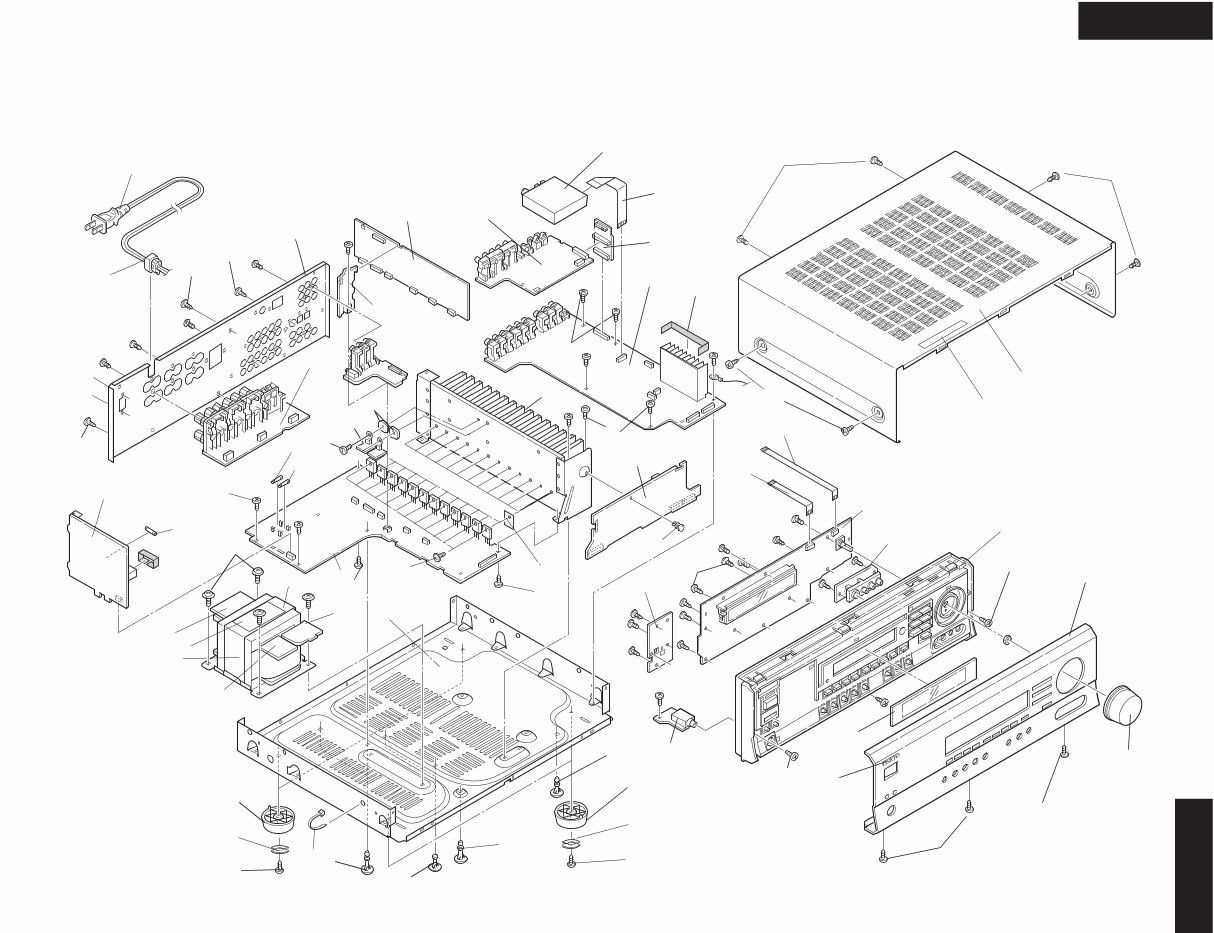
EXPLODED VIEW
HT-R510
P901
11
33
33
31
U9
U31
U17
U26
2
2
17
17
17
16
P7502
P7503
24
53
51
1
2
25
U3
U6
P101
53
52
2
U5
U1
2
U15
33
F901
U24
9
U23
T901
9
U25
U13
13
Q6050
Q6065
55
12
21
22
23
21
22
23
8
8
7
6
U21
F6901
F6902
U14
2
U12
10
2
U4
5
54
2
56
U27
U28
2
18
63
Q6060
Q6055
U10

HT-R510
WIRING VIEW
JL6952B
JL6951B
P911A
P912A
P913A
7
3
1
5
JL9501B
P6072
JL6804A
P6922
P6923
P6301
P995A
P931
JL6952A
JL6951A
D6706
D6705
C6708
P6907
P6909
JL6805A
P997A
P996A
P6906
P995B
P6910
P6801
JL6803A
P6011A
P6073A
JL6402A
COM
TH1
P6072A
ID-
ID+
-B1
ID- ID+
ID- ID+
ID- ID+
ID- ID+
ID- ID+ ID+
P6931
P6083
P6084
P6085
P6082
P6081
P6003
P6004
P6005
P6002
P6001
P6000
R6043
R6044
R6045
R6042
R6041
R6040
P6802
R
L
TH2
P6903
P6080
JL7502A
P7501
JL7502B
NADIS-7403,Display circui
NASW-7404,
Standby switch
PC board ass'y
NAETC-7405,
Headphone
terminal PC
board ass'y
NAETC-783
circuit PC b
NAETC-7834,
Secondary
PC board ass'y
NAETC-7835,Speaker
terminal PC board ass'y
NAAF-7842,
Power amplifier
PC board ass'y
NAPS-7844,
Transformer
terminal
PC board ass'y
U24
NAPS-7845,Primary circuit
PC board ass'y
NAPS-7846,
Secondary
terminal
PC board ass'y
U13
U25
U23
T901
POWER
TRANS-
FORMER
NPT-1465D
U3
U4
U5
U21
U14
U28
P902
P901A
P909
P908
T902
AC-G
S902
P917
P918
P911
P922 P923
E921
AC-H
P931A
120V
220V
P921A
P921
P922A
P923A
P913 P912
P926
P925
AC-G AC-H
15 16 17 18 19
JL7501B
NCSW-7404
JL7501A
14 13 12 11 10 9 8
JL6805B
JL6803B
JL6804B
NCETC-7835
P6800 P6802
P6801
P6931A
JL9501
A
1
2
3
4
5
B C D
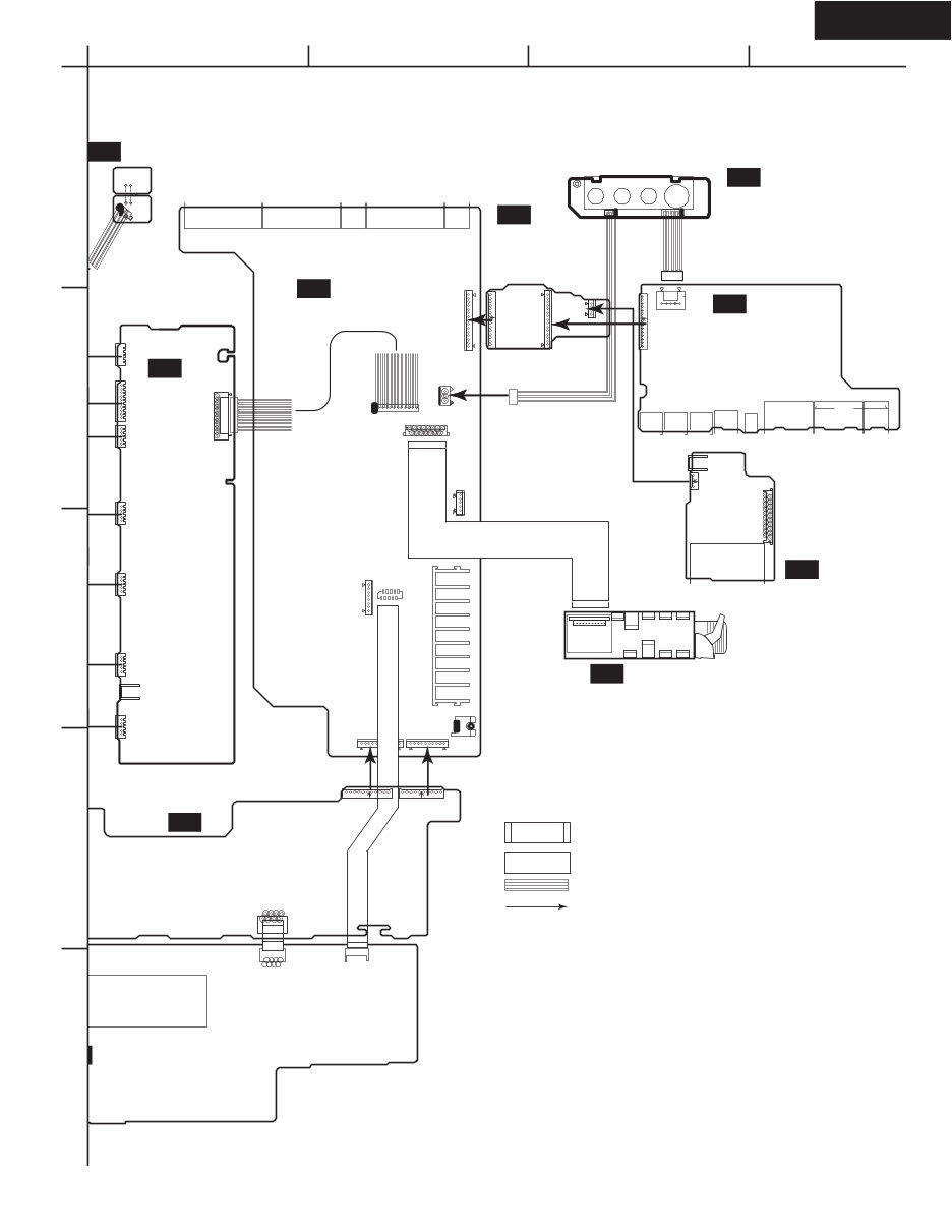
HT-R510
WIRING VIEW
P7701
P253B P261B
V4C
GND
GND
V4Y
V4
P101
P301 P302 P304 P305
P306
P261A
P351
P801
P410B
P411B
P412B
P6403
P7502B
P7701
P7502A P7503A
FLAC
FLAC
GND
GND
HPL
HPE
HPR
+5.6V
NADG-7821,
DSP circuit
PC board ass'y
ircuit PC board ass'y
NAETC-7406,
Front video
PC board ass'y NAETC-7838,
Connector PC
board ass'y
NAAF-7830,
Driver circuit
PC board ass'y
-7833,Const. voltage
PC board ass'y
NAVD-7847,Video
circuit PC board ass'y
TUNER
PACK
U12
U6
U17
U26
U1
U9
U28
: Flat cable
: Jumper Wire
: Socket
: PC board to PC board
P282
P201
P203
P204
P202
P253A
P281
U281
U282 U283
JL6402B
NAETC-7849,
Thermal detector
PC board ass'y
U31
P242A
P243B
P241
P801B
P206A
P243A
P6011A
P6000A
P6001A
P6002A
P6003A P6004A
P6005A
P306A
A
P7503B
P410A
P411A
NAVD-7831,Component
video PC board ass'y
U10
P206B
A
1
2
3
4
5
B C D
HT-R510
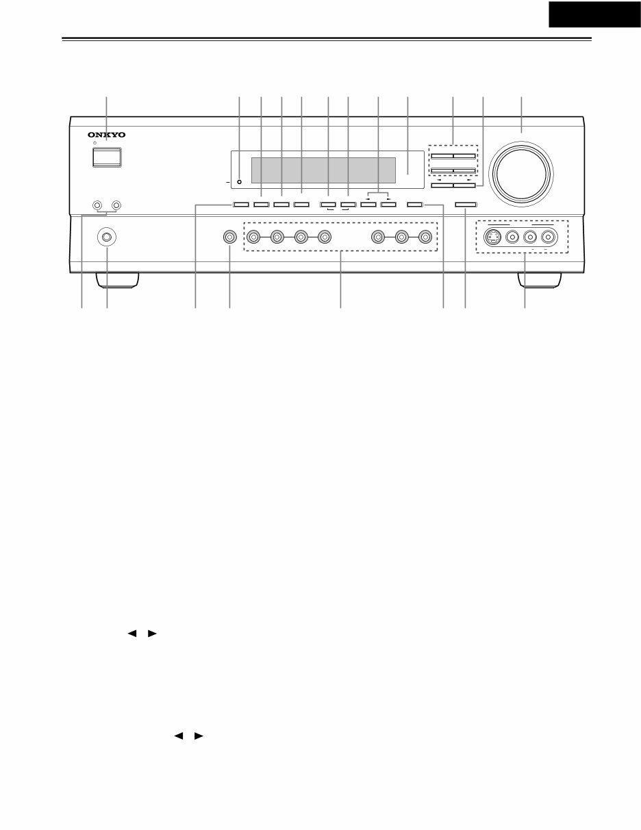
Controls & Connectors
Front Panel
A STANDBY/ON button
This button is used to set the HT-R510 to On or Standby. For
models with a POWER switch, this button has no effect unless
the POWER switch is set to ON.
B STANDBY indicator
This indicator lights up when the HT-R510 is in Standby
mode, and it flashes while a signal is being received from the
remote controller.
C DIMMER button
This button is used to adjust the display brightness.
D DIGITAL INPUT button
This button is used to assign the digital inputs.
E SUBWOOFER MODE button
This button is used to select the Subwoofer modes.
F MEMORY button
This button is used when storing and deleting radio presets.
G FM MODE button
This button is used to select the FM radio Stereo and Mono
modes. It’s also used when deleting radio presets.
H TUNING [ ] [ ] buttons
These buttons are used to tune into radio stations.
I Remote control sensor
This sensor receives control signals from the remote control-
ler.
J Listening mode buttons
These buttons are used to select the listening modes.
K PRESET/ADJUST [ ] [ ] buttons
This button is used to select radio presets and adjust parameter
values.
L MASTER VOLUME control
This control is used to set the volume of the HT-R510.
M SPEAKER A & B buttons
These buttons are used to turn speaker sets A and B on and off.
N PHONES jack
This 1/4-inch phone jack is for connecting a standard pair of
stereo headphones for private listening.
O DISPLAY button
This button is used to display various information about the
currently selected source.
P AUDIO SELECTOR button
This button is used to select the input signal format.
Q Input selector buttons
These buttons are used to select the audio and video sources:
CD, DVD, TAPE, TUNER, VIDEO 1, VIDEO 2, or VIDEO 3.
R SPEAKER ADJUST button
This button is used to adjust various speaker-related parame-
ters.
S AUDIO ADJUST button
This button is used to set the Bass, Treble, Late Night, Cinema
Filter, Center Image, Panorama, Dimension, and Center Width
functions.
T VIDEO 3 INPUT connectors
These S-Video, composite video (RCA/phono), and analog
audio (RCA/phono) inputs can be used to connect a video
camera or games console.
STANDBY/ON
PHONES
MASTER VOLUME
VIDEO 2 TAPE TUNER CD VIDEO 3 DVD
A B SPEAKERS DIMMER
SURROUND
VIDEO 1
VCR
AUDIO
SELECTOR
DSP
STEREO
STANDBY
DISPLAY AUDIO ADJUST SPEAKER ADJUST FM MODE
SUBWOOFER
MODE DIGITAL INPUT MEMORY
DIRECT
S VIDEO AUDIO VIDEO L R
TUNING
CLEAR
PRESET/ADJUST
VIDEO 3 INPUT
N P Q S T R O
1 234 7 8 9 J L K 5
M
6

HT-R510
Controls & Connectors—Continued
Display
1 A & B speaker indicators
Indicator A lights up when speaker set A is on. Indicator B
lights up when speaker set B is on.
2 MUTING indicator
This indicator flashes when the HT-R510 is muted.
3 Source/listening mode indicators
These indicators display information about the currently
selected source and listening mode.
4 Tuning indicators
TUNED: This indicator lights up when the HT-R510 is
tuned into a radio station.
AUTO: This indicator lights up when the Auto Tuning
function is on.
MEMORY: This indicator lights up when programming
radio presets.
FM STEREO: This indicator lights up when the
HT-R510 is tuned into a stereo FM station.
5 SLEEP indicator
This indicator lights up when the Sleep function has been set.
6 Message area
This area of the display shows various information about the
currently selected source.
12 3 4
5 6
Controls & Connectors—Continued
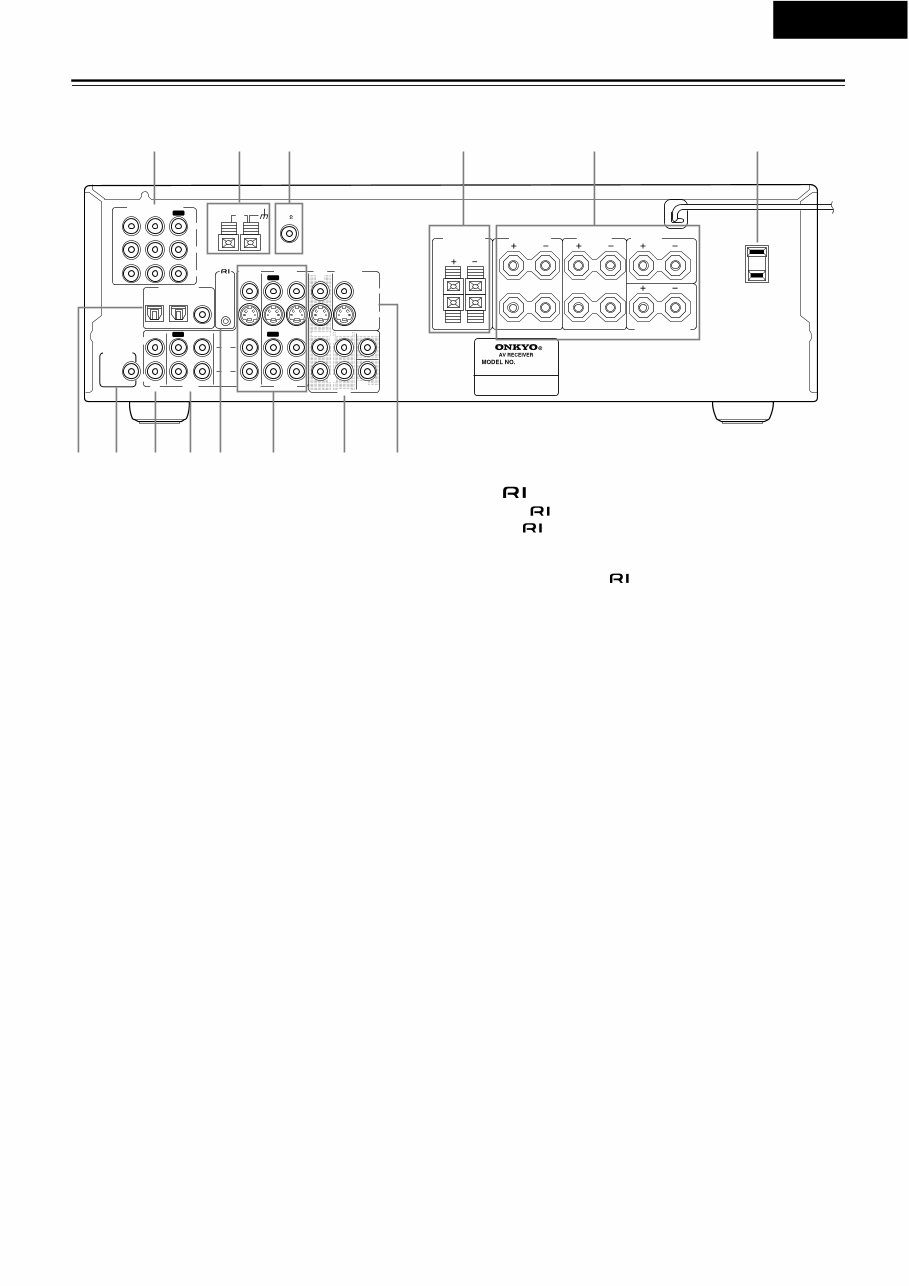
Rear Panel
A COMPONENT VIDEO
These RCA/phono connectors can be used to connect a TV,
DVD player, or other AV component with component video
inputs and outputs.
B AM ANTENNA
These push terminals are for connecting an AM antenna.
C FM ANTENNA
This connector is for connecting an FM antenna.
D FRONT SPEAKERS B
These push terminals are for connecting speaker set B.
E FRONT SPEAKERS A, SURROUND SPEAKERS,
CENTER SPEAKER & SURROUND BACK
SPEAKER
These terminal posts are for connecting speaker set A, includ-
ing the front, surround, center, and surround-back speakers.
They accept bare wires or banana plugs.
F AC OUTLET
This switched AC outlet can be used to supply power to
another AV component.
G DIGITAL INPUT OPTICAL 1, 2 & COAXIAL
These optical and coaxial connectors can be used to connect a
CD, DVD, or LD (laser disc) player, or other AV component
with digital outputs.
H SUBWOOFER PRE OUT
This RCA/phono connector can be used to connect an active
subwoofer.
I CD IN
These RCA/phono connectors can be used to connect a CD
player with analog outputs.
J TAPE IN/OUT
These RCA/phono connectors can be used to connect a cas-
sette recorder, MiniDisc recorder, or other recorder with ana-
log inputs and outputs.
K
This (Remote Interactive) connector can be connected to
the connector on another Onkyo AV component, for
example, a CD player, DVD player, or cassette recorder. The
HT-R510’s remote controller can then be used to control that
component. To use , you must make an analog RCA/
phono connection between your HT-R510 and the other AV
component, even if they are connected digitally.
L VIDEO 1 IN/OUT & VIDEO 2 IN
These connectors can be used to connect a VCR or other AV
component. There are RCA/phono connectors for connecting
to stereo analog audio inputs and outputs, and S-Video and
composite video (RCA/phono) connectors for connecting to
video inputs and outputs.
M DVD IN/MULTI CH INPUT
The FRONT, SURR, CENTER, and SUBWOOFER RCA/
phono connectors can be used to connect AV components with
multiple analog audio outputs, including DVD players with
individual 5.1 surround analog outputs. There’s an S-Video
input and composite video (RCA/phono) input for connecting
the video signal.
N MONITOR OUT
These S-Video and composite video (RCA/phono) outputs can
be connected to the video input on your TV or projector.
Tip:
A turntable with a built-in preamp can be connected to a pair of
unused HT-R510 analog inputs. To connect a turntable without
a built-in preamp, you’ll need a commercially available phono
preamp.
L
R
R
L
R
L
ANTENNA
FM
75
AM
FRONT
SPEAKERS A
FRONT
SPEAKERS B
SURROUND
SPEAKERS
CENTER
SPEAKER
R
L
SURROUND BACK
SPEAKER
REMOTE
CONTROL
IN IN IN
OPTICAL COAXIAL
1 2
IN IN IN IN FRONT SURR CENTER
SUB
WOOFER
OUT
OUT OUT
DIGITAL INPUT
VIDEO 2 VIDEO 1 DVD MONITOR
OUT
VIDEO
S VIDEO
DVD
TAPE CD
L
R
VIDEO 2 VIDEO 1
SUBWOOFER
PRE OUT
VIDEO 1/2/3
IN
DVD IN
COMPONENT VIDEO
Y
PB
PR
OUT
L
R
AC OUTLET
AC 120V 60Hz
SWITCHED
120W 1A MAX.
HT-R510
1 6
789JK M N
4 5 3 2
L
HT-R510

HT-R510
Specifications
AMPLIFIER SECTION
VIDEO SECTION
TUNER SECTION
FM
AM
GENERAL
REMOTE CONTROL
Specifications and features are subject to change without notice. Power sup-
ply and voltage vary depending on the area in which the unit is purchased.
Continuous Average Power output (FTC)
All channels: 100 watts per channel min. RMS at
8 Ω, 2 channels driven from 20 Hz
to 20 kHz with no more than 0.08%
total harmonic distortion.
Dynamic power output:
230 watts × 2 at 3 Ω
170 watts × 2 at 4 Ω
115 watts × 2 at 8 Ω
Total Harmonic Distortion: 0.08% at rated power
0.08% at 1 watt output
IM Distortion: 0.08% at rated power
0.08% at 1 watt output
Damping Factor: 60 at 8 Ω
Input Sensitivity and Impedance
DIGITAL INPUT (OPTICAL 1, 2): 0.5 Vp-p, 75 Ω
DIGITAL INPUT (COAXIAL): 0.5 Vp-p, 75 Ω
LINE (CD, VIDEO 1, 2, 3, TAPE): 200 mV, 47 kΩ
Multichannel Input
(DVD FRONT L/C/R, SURR L/R): 200 mV, 47 kΩ
(SUBWOOFER): 36 mV, 47 kΩ
Output Level and Impedance
Rec out (TAPE, VIDEO 1): 200 mV, 470 Ω
Pre out (SUBWOOFER): 1 V, 470 Ω
Frequency Response: 10 Hz to 100 kHz,
+1/–3 dB (Direct mode)
Tone Control
Bass: ±12 dB at 20 Hz
Treble: ±12 dB at 20 kHz
Signal-to-Noise Ratio: CD/TAPE: 100 dB
(IHF-A, Direct mode)
Muting: –50 dB
Input Sensitivity and Impedance
VIDEO (DVD, VIDEO 1, 2, 3): 1 Vp-p, 75 Ω
S VIDEO (DVD, VIDEO 1, 2, 3): 1 Vp-p, 75 Ω (Y)
0.28 Vp-p, 75 Ω (C)
COMPONENT VIDEO 1, 2: 1 Vp-p, 75 Ω (Y)
0.7 Vp-p, 75 Ω (P
B
, P
R
)
Output Level and Impedance
VIDEO (VIDEO 1, 2, MONITOR): 1 Vp-p, 75 Ω
S VIDEO (VIDEO 1, 2, MONITOR): 1 Vp-p, 75 Ω (Y)
0.28 Vp-p, 75 Ω (C)
COMPONENT VIDEO OUT: 1 Vp-p, 75 Ω (Y)
0.7 Vp-p, 75 Ω (P
B
, P
R
)
Tuning Range: 87.50-108.00 MHz (100 kHz steps)
Usable Sensitivity
Mono: 11.2 dBf, 1.0 μV (75 Ω, IHF)
0.9 μV (75 Ω, DIN)
Stereo: 17.2 dBf, 2.0 μV (75 Ω, IHF)
23 μV (75 Ω DIN)
50 dB Quieting Sensitivity
Mono: 17.2 dBf, 2.0 μV (75 Ω)
Stereo: 37.2 dBf, 20.0 μV (75 Ω)
Capture Ratio: 2.0 dB
Image Rejection Ratio: 40 dB
IF Rejection Ratio: 90 dB
Signal-to-Noise Ratio
Mono: 76 dB
Stereo: 70 dB
Alternate Channel Attenuation: 55 dB
Selectivity: 50 dB (DIN)
AM Suppression Ratio: 50 dB
Total Harmonic Distortion
Mono: 0.2%
Stereo: 0.3%
Frequency Response: 30 Hz-15 kHz, –1.0 dB
Stereo Separation: 45 dB at 1 kHz
30 dB at 100 Hz-10 kHz
Tuning Range: 530-1,710 kHz (10 kHz steps)
Usable Sensitivity: 30 μV
Image Rejection Ratio: 40 dB
IF Rejection Ratio: 40 dB
Signal-to-Noise Ratio: 40 dB
Total Harmonic Distortion: 0.7%
Power Supply and Power Consumption:
AC 120 V, 60 Hz 5.2 A
Dimensions (W × H × D): 17-1/8" × 5-7/8" × 14-13/16"
435 × 150 × 376 mm
Weight: 21.8 lbs., 9.9 kg
Transmitter: Infrared
Signal range: Approx. 16 ft., 5 meters
Power supply:
Two “AA” batteries (1.5 V × 2)
HT-R510
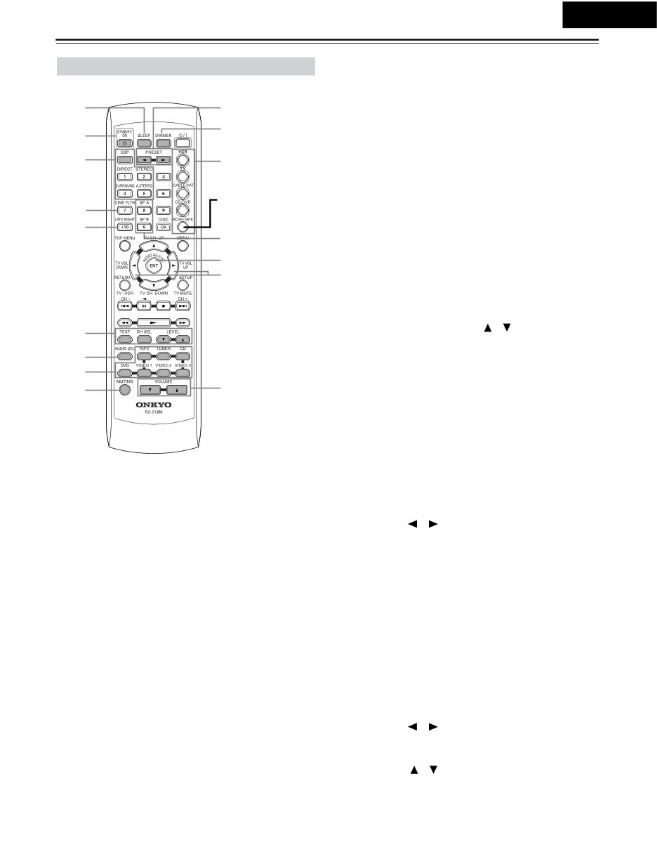
Controls & Connectors—Continued
RC-518M
This page describes only those buttons that can be used to
control the HT-R510 when the remote controller is in RCVR
mode (Receiver mode).
To select RCVR mode, press the [RCVR] button.
A SLEEP button
This button is used to set the Sleep function. This function can
be set only with the remote controller.
B STANDBY/ON button
This button is used to set the HT-R510 to On or Standby.
C Listening mode buttons
These buttons are used to select the listening modes.
D CINE FLTR button
This button is used to set the Cinema Filter function.
E LATE NIGHT button
This button is used to set the Late Night function.
F TEST, CH SEL & LEVEL [ ] [ ] buttons
These buttons are used to set the level of each speaker individ-
ually. This function can be set only with the remote controller.
G AUDIO SEL button
This button is used to select analog or digital inputs for the
CD, DVD, TAPE, VIDEO 1, VIDEO 2, and VIDEO 3 sources.
H Input selector buttons
These buttons are used to select the audio and video sources:
CD, DVD, TAPE, TUNER, VIDEO 1, VIDEO 2, and
VIDEO 3.
I MUTING button
This button is used to mute the HT-R510. This function can be
set only with the remote controller.
J PRESET [ ] [ ] buttons
These buttons are used to select radio presets.
K DIMMER button
This button is used to adjust the display brightness.
L Remote Controller Mode buttons
These buttons are used to select the remote controller modes.
To select RCVR mode, press the [RCVR] button.
M SP A & SP B buttons
These buttons are used to turn on and off speaker sets A and B
individually.
N AUDIO ADJUST button
This button is used to set the Bass, Treble, Late Night, Cinema
Filter, Center Image, Panorama, Dimension, and Center Width
functions.
O ADJUST [ ] [ ] buttons
These buttons are used to adjust the functions selected with
the AUDIO ADJUST button.
P VOLUME [ ] [ ] buttons
These buttons are used to set the volume of the HT-R510.
Remote Controller—RCVR Mode
1 J
K
2
3
4
5
M
O
6
7
9
L
N
P
8
Press this to select
RCVR mode
You're Reading a Preview
What's Included?
Fast Download Speeds
Online & Offline Access
Access PDF Contents & Bookmarks
Full Search Facility
Print one or all pages of your manual
$31.99
Viewed 73 Times Today


Secure transaction
What's Included?
Fast Download Speeds
Online & Offline Access
Access PDF Contents & Bookmarks
Full Search Facility
Print one or all pages of your manual
$31.99
The Onkyo HT-R510 AV RECEIVER Service Manual is a valuable resource for both professional mechanics and DIY enthusiasts. This manual, available in English, provides comprehensive technical information essential for repairing and maintaining the Onkyo HT-R510 AV RECEIVER. Whether you are troubleshooting, repairing, or conducting regular maintenance, this manual offers detailed insights to assist you in your tasks.
It is available in PDF format, ensuring easy access and compatibility across various devices. With its clear and concise instructions, diagrams, and schematics, this manual is an indispensable tool for anyone working with the Onkyo HT-R510 AV RECEIVER.


