

Sony STR-DG500 DG600 Service Manual
What's Included?
Fast Download Speeds
Online & Offline Access
Access PDF Contents & Bookmarks
Full Search Facility
Print one or all pages of your manual
1
SERVICE MANUAL
US Model
Canadian Model
STR-DG500/DG600
AEP Model
UK Model
STR-DG500
E Model
STR-DG500/DG600
Australian Model
STR-DG500
STR-DG500/DG600
MULTI CHANNEL AV RECEIVER
AUDIO POWER SPECIFICATIONS
POWER OUTPUT AND TOTAL HARMONIC
DISTORTION:
(Models of area code US only)
With 8 ohm loads, both channels driven, from
20 – 20,000 Hz; rated 100 watts per channel
minimum RMS power, with no more than
0.09 % total harmonic distortion from 250
milliwatts to rated output.
Amplifier section
Power Output
Models of area code US, CND
Stereo Power Output
1)
, Reference Power Output
1) 2)
8 ohms 20 Hz – 20 kHz, THD 0.09 %
100 W + 100 W, 110 W/ch
8 ohms 1 kHz, THD 0.7 %
110 W + 110 W, 120 W/ch
8 ohms 1 kHz, THD 10 %
125 W + 125 W, 150 W/ch
Models of area code AEP, UK, E2, TW, AUS
Stereo Power Output
1)
, Reference Power Output
1) 2)
8 ohms 20 Hz – 20 kHz, THD 0.09 %
85 W + 85 W, 110 W/ch
8 ohms 1 kHz, THD 0.7 %
100 W + 100 W, 120 W/ch
8 ohms 1 kHz, THD 10 %
125 W + 125 W, 150 W/ch
SPECIFICATIONS
Models of area code SP, MY
Stereo Power Output
1)
, Reference Power Output
1) 2)
8 ohms 20 Hz – 20 kHz, THD 0.09 %
70 W + 70 W, 90 W/ch
8 ohms 1 kHz, THD 0.7 %
80 W + 80 W, 100 W/ch
8 ohms 1 kHz, THD 10 %
100 W + 100 W, 125 W/ch
Models of area code KR
Stereo Power Output
1)
, Reference Power Output
1) 2)
8 ohms 20 Hz – 20 kHz, THD 0.09 %
85 W + 85 W
1)
,
70 W + 70 W
3)
, 110 W/ch
8 ohms 1 kHz, THD 0.7 %
100 W + 100 W
1)
,
90 W + 90 W
3)
, 120 W/ch
8 ohms 1 kHz, THD 10 %
125 W + 125 W
1)
,
110 W + 110 W
3)
, 150 W/ch
Models of area code TH
Stereo Power Output
1)
, Reference Power Output
1) 2)
8 ohms 20 Hz – 20 kHz, THD 0.09 %
70 W + 70 W
1)
,
60 W + 60 W
3)
, 90 W/ch
8 ohms 1 kHz, THD 0.7 %
80 W + 80 W
1)
,
70 W + 70 W
3)
, 100 W/ch
8 ohms 1 kHz, THD 10 %
100 W + 100 W
1)
,
90 W + 90 W
3)
, 125 W/ch
Ver. 1.1 2006. 04
9-887-127-02
2006D04-1
© 2006. 04
Sony Corporation
Home Audio Division
Published by Sony Techno Create Corporation
Manufactured under license from Dolby Laboratories.
“Dolby”, “Pro Logic”, “Surround EX”, and the double-D
symbol are trademarks of Dolby Laboratories.
“DTS”, “DTS-ES”, “Neo:6”, and “DTS 96/24” are
trademarks of Digital Theater Systems, Inc.
– Continued on next page –
Photo: STR-DG600: Silver type

2
STR-DG500/DG600
1) Measured under the following conditions:
Area code Power requirements
US, CND 120 V AC, 60 Hz
AEP, UK, KR, MY, SP, TH 230 V AC, 50 Hz
E2, AUS 240 V AC, 50 Hz
TW 110 V AC, 60 Hz
2) Reference power output for front, center, surround
and surround back. Depending on the sound field
settings and the source, there may be no sound output.
3) Measured under the following conditions:
Area code Power requirements
KR, TH 220 V AC, 50 Hz
Frequency response
Analog 10 Hz – 70 kHz
+0.5/–2 dB (with sound
field and tone (DG500) or
equalizer (DG600) bypassed)
Inputs
Analog Sensitivity: 500 mV/
50 kohms
S/N
4)
: 96 dB
(A, 500 mV
5)
)
Digital (Coaxial) Impedance: 75 ohms
S/N: 100 dB
(A, 20 kHz LPF)
Digital (Optical) S/N: 100 dB
(A, 20 kHz LPF)
Output (Analog)
AUDIO OUT Voltage: 500 mV/10 kohms
SUB WOOFER, SURROUND (DG600)
Voltage: 2 V/1 kohm
Tone (DG500), EQUALIZER (DG600)
Gain levels ±6 dB, 1 dB step
4) INPUT SHORT (with sound field and tone (DG500) or
equalizer (DG600) bypassed).
5) Weighted network, input level.
FM tuner section
Tuning range 87.5 – 108.0 MHz
Intermediate frequency 10.7 MHz
Useable sensitivity 11.2 dBf, 1 μV/75 ohms
S/N
Mono/Stereo 76 dB/70 dB
Harmonic distortion at 1 kHz
Mono/Stereo 0.3%/0.5%
Separation 45 dB at 1 kHz
Frequency response 30 Hz – 15 kHz,
+0.5/–2 dB
AM tuner section
Tuning range
Models of area code US, CND
With 10-kHz tuning scale: 530 – 1,710 kHz
6)
With 9-kHz tuning scale: 531 – 1,710 kHz
6)
Models of area code E2
With 10-kHz tuning scale: 530 – 1,610 kHz
6)
With 9-kHz tuning scale: 531 – 1,602 kHz
6)
Models of area code AEP, UK, AUS, TW, KR, SP, MY,
TH
With 9-kHz tuning scale: 531 – 1,602 kHz
Intermediate frequency 450 kHz
Usable sensitivity 50 dB/m (at 1,000 kHz or
999 kHz)
6) You can change the AM tuning scale to 9 kHz or 10 kHz.
After tuning in any AM station, turn off the receiver. While
holding down TUNING MODE, press ?/1. All preset
stations will be erased when you change the tuning scale.
To reset the scale to 10 kHz (or 9 kHz), repeat the
procedure.
Video section
Inputs/Outputs
Video: 1 Vp-p, 75 ohms
S-video (DG600): Y: 1 Vp-p, 75 ohms
C: 0.286 Vp-p, 75 ohms
COMPONENT VIDEO: Y: 1 Vp-p, 75 ohms
PB/CB/B-Y: 0.7 Vp-p/
75 ohms
PR/CR/R-Y: 0.7 Vp-p/
75 ohms
80 MHz HD Pass Through
General
Power requirements
Area code Power requirements
US, CND 120 V AC, 60 Hz
AEP, UK 230 V AC, 50/60 Hz
AUS 240 V AC, 50 Hz
KR, TH 220 – 230 V AC, 50/60 Hz
E2 120/220/240 V AC, 50/60 Hz
TW 110 V AC, 50/60 Hz
SP, MY 230 – 240 V AC, 50/60 Hz
Power consumption
Area code Power consumption
DG500: US, AEP, UK, 220 W
AUS, KR, E2
DG500: SP, MY, TH 200 W
DG500: CND 300 VA
DG500: TW 500 W
DG600: US 230 W
DG600: CND 310 VA
DG600: E2 230 W
DG600: SP, MY, TH 210 W
Power consumption (during standby mode)
0.2 W
AC outlets (DG600)
Area code AC outlets
US, CND 1 switched, 120 W/1A MAX
E2, SP, MY, TH 1 switched, 100 W/0.4A MAX
Dimensions (w/h/d) (Approx.)
430 × 157.5 × 316 mm
(16 7/8 × 6 2/8 × 12 4/8
inches) including
projecting parts and
controls
Mass (Approx.) 8.0 kg (17 lb 11 oz)
Supplied accessories
FM wire antenna (1)
AM loop antenna (1)
Remote commander RM-AAU005 (1) (DG500)
Remote commander RM-AAP012 (1) (DG600: US, CND)
Remote commander RM-AAP013 (1) (DG600: E2, MY,
SP, TH)
R6 (size-AA) batteries (2)
Optimizer microphone ECM-AC2 (1)
Design and specifications are subject to change
without notice.
• Abbreviation
CND : Canadian model
E2 : 120 V AC area in E model
TW : Taiwan model
AUS : Australian model
KR : Korea model
MY : Malaysia model
SP : Singapore model
TH : Thai model
Ver. 1.1
3
STR-DG500/DG600
SAFETY-RELATED COMPONENT WARNING!!
COMPONENTS IDENTIFIED BY MARK 0 OR DOTTED LINE
WITH MARK 0 ON THE SCHEMATIC DIAGRAMS AND IN
THE PARTS LIST ARE CRITICAL TO SAFE OPERATION.
REPLACE THESE COMPONENTS WITH SONY PARTS WHOSE
PART NUMBERS APPEAR AS SHOWN IN THIS MANUAL OR
IN SUPPLEMENTS PUBLISHED BY SONY.
ATTENTION AU COMPOSANT AYANT RAPPORT
À LA SÉCURITÉ!!
LES COMPOSANTS IDENTIFIÉS PAR UNE MARQUE 0 SUR LES
DIAGRAMMES SCHÉMATIQUES ET LA LISTE DES PIÈCES
SONT CRITIQUES POUR LA SÉCURITÉ DE FONCTIONNEMENT.
NE REMPLACER CES COMPOSANTS QUE PAR DES PIÈCES
SONY DONT LES NUMÉROS SONT DONNÉS DANS CE MANUEL
OU DANS LES SUPPLÉMENTS PUBLIÉS PAR SONY.
1.5 k Ω 0.15 μF
AC
voltmeter
(0.75 V)
To Exposed Metal
Parts on Set
Earth Ground
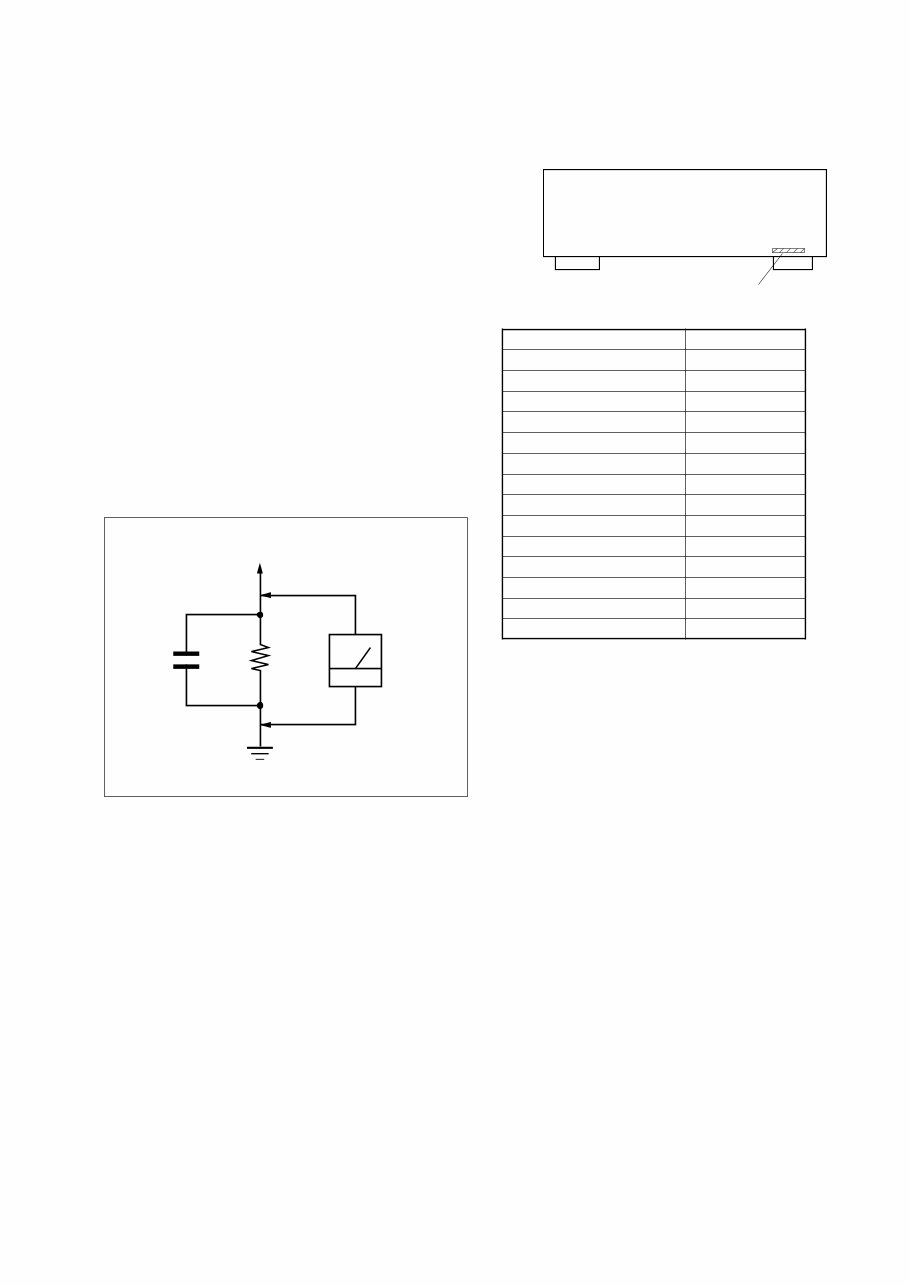
SAFETY CHECK-OUT (US MODEL)
After correcting the original service problem, perform the follow-
ing safety check before releasing the set to the customer:
Check the antenna terminals, metal trim, “metallized” knobs, screws,
and all other exposed metal parts for AC leakage.
Check leakage as described below.
LEAKAGE TEST
The AC leakage from any exposed metal part to earth ground and
from all exposed metal parts to any exposed metal part having a
return to chassis, must not exceed 0.5 mA (500 microampers.).
Leakage current can be measured by any one of three methods.
1. A commercial leakage tester, such as the Simpson 229 or RCA
WT-540A. Follow the manufacturers’ instructions to use these
instruments.
2. A battery-operated AC milliammeter. The Data Precision 245
digital multimeter is suitable for this job.
3. Measuring the voltage drop across a resistor by means of a
VOM or battery-operated AC voltmeter. The “limit” indica-
tion is 0.75 V, so analog meters must have an accurate low-
voltage scale. The Simpson 250 and Sanwa SH-63Trd are ex-
amples of a passive VOM that is suitable. Nearly all battery
operated digital multimeters that have a 2 V AC range are suit-
able. (See Fig. A)
Fig. A. Using an AC voltmeter to check AC leakage.
MODEL IDENTIFICATION
— BACK PANEL —
Part No.
MODEL PART No.
DG500: US 2-661-146-0s
DG500: CND 2-661-146-1s
DG500: AEP, UK 2-661-146-2s
DG500: TH 2-661-146-3s
DG500: AUS 2-661-146-4s
DG500: TW 2-661-146-5s
DG500: KR 2-661-146-6s
DG500: E2 2-661-146-7s
DG600: US 2-661-147-0s
DG600: CND 2-661-147-1s
DG600: TH 2-661-147-3s
DG600: E2 2-661-147-5s
DG600: MY, SP 2-661-147-9s
DG500: MY, SP 2-686-376-0s
• Abbreviation
CND : Canadian model
AUS : Australian model
TW : Taiwan model
KR : Korea model
E2 : 120 V AC area in E model
MY : Malaysia model
SP : Singapore model
TH : Thai model
Ver. 1.1

4
STR-DG500/DG600
TABLE OF CONTENTS
Ver. 1.1
1. GENERAL
Description and location of parts (STR-DG500) .................... 5
Description and location of parts
(STR-DG600: US, CND model) ............................................. 7
2. DISASSEMBLY
2-1. Case ................................................................................... 10
2-2. Front Panel Section ........................................................... 11
2-3. Back Panel Section ............................................................ 11
2-4. DIGITAL Board ................................................................ 12
2-5. MAIN Board Section ........................................................ 12
2-6. STANDBY Board ............................................................. 13
2-7. SB AMP Board (DG600) .................................................. 13
3. TEST MODE ..................................................................... 14
4. DIAGRAMS
4-1. Block Diagram – Tuner/Audio Section – .......................... 15
4-2. Block Diagram – Digital Section – ................................... 16
4-3. Block Diagram – Video Section – ..................................... 17
4-4. Block Diagram
– XM Section (DG600: US, CND model) – ..................... 18
4-5. Block Diagram – Key/Display Section – .......................... 19
4-6. Block Diagram – Power Section – .................................... 20
4-7. Circuit Boards Location .................................................... 21
4-8. Printed Wiring Boards – Main Section – .......................... 22
4-9. Schematic Diagram – Main Section (1/3) – ...................... 23
4-10. Schematic Diagram – Main Section (2/3) – ...................... 24
4-11. Schematic Diagram – Main Section (3/3) – ...................... 25
4-12. Printed Wiring Board – Digital Section (1/2) – ................ 26
4-13. Printed Wiring Board – Digital Section (2/2) – ................ 27
4-14. Schematic Diagram – Digital Section (1/5) – ................... 28
4-15. Schematic Diagram – Digital Section (2/5) – ................... 29
4-16. Schematic Diagram – Digital Section (3/5) – ................... 30
4-17. Schematic Diagram – Digital Section (4/5) – ................... 31
4-18. Schematic Diagram – Digital Section (5/5) – ................... 32
4-19. Printed Wiring Boards
– Center/Surround Back Speaker Section – ...................... 33
4-20. Schematic Diagram
– Center/Surround Back Speaker Section – ...................... 34
4-21. Printed Wiring Board – Front B Speaker Section – .......... 35
4-22. Schematic Diagram – Front B Speaker Section – ............. 35
4-23. Printed Wiring Board – Video Section – ........................... 36
4-24. Schematic Diagram – Video Section – .............................. 37
4-25. Printed Wiring Board – S-video Section – ........................ 38
4-26. Schematic Diagram – S-video Section – ........................... 38
4-27. Printed Wiring Board
– S-video Up Convert Section (DG600) – ........................ 39
4-28. Schematic Diagram
– S-video Up Convert Section (DG600) – ........................ 39
4-29. Printed Wiring Board
– XM Section (DG600: US, CND model) – ..................... 40
4-30. Schematic Diagram
– XM Section (DG600: US, CND model) – ..................... 41
4-31. Printed Wiring Board – ADCC Section – ......................... 42
4-32. Schematic Diagram – ADCC Section – ............................ 42
4-33. Printed Wiring Boards – Display Section – ...................... 43
4-34. Schematic Diagram – Display Section – ........................... 44
4-35. Printed Wiring Boards – Power Section – ......................... 45
4-36. Schematic Diagram – Power Section – ............................. 46
5. EXPLODED VIEWS
5-1. Case Section ...................................................................... 58
5-2. Front Panel Section ........................................................... 59
5-3. Back Panel Section ............................................................ 60
5-4. Chassis Section ................................................................. 61
6. ELECTRICAL PARTS LIST ........................................ 62
5
STR-DG500/DG600
SECTION 1
GENERAL This section is extracted
from instruction manual.
5
GB
Getting Started
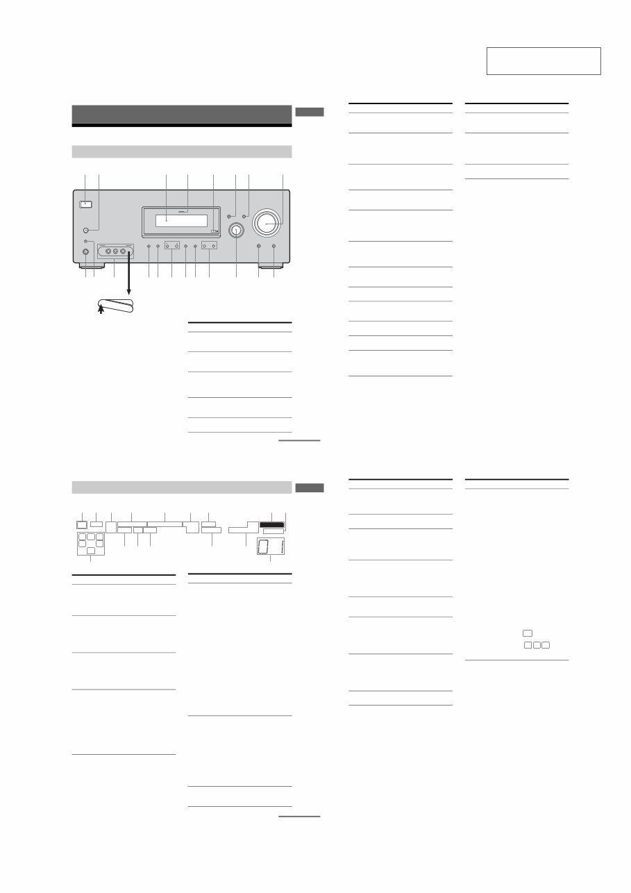
Description and location of parts
To remove the cover
Press PUSH.
When you remove the cover, keep it out of
reach from children.
Getting Started
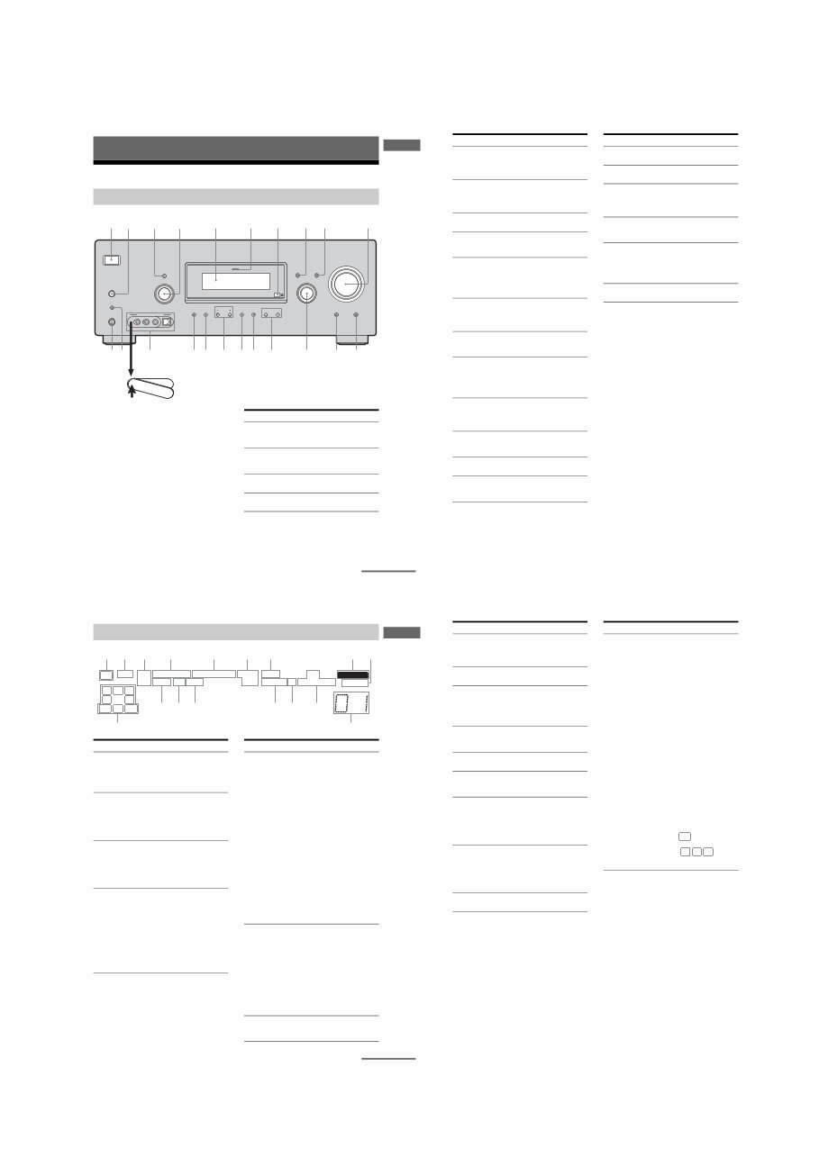
Front panel
?/1
AUTO CAL MIC
SPEAKERS
(OFF/A/B /A+B)
PHONES
VIDEO 3 IN/PORTABLE AV IN
VIDEO L AUDIO R
MEMORY/
ENTER
TUNING
MODE TUNING 2CH A.F.D. MOVIE MUSIC MULTI CH IN DIRECT
DISPLAY
MULTI CHANNEL DECODING
INPUT MODE
INPUT SELECTOR
MASTER VOLUME
1 3 2 4 6 8 7 5
9 q; w; qa qs qk ql qd qf qg qh qj
PUSH
Name Function
A?/1 Press to turn the receiver
on or off (page 25, 32, 33,
53, 55, 73).
BSPEAKERS
(OFF/A/B/A+B)
Press to select OFF, A, B,
A+B of the front speakers
(page 26).
CDisplay The current status of the
selected component or a
list of selectable items
appears here (page 7).
DMULTI CHANNEL
DECODING lamp
Lights up when multi
channel audio is decoded
(page 33).
ERemote sensor Receives signals from
remote commander.
continued
6
GB
Name Function
FDISPLAY Press to select information
displayed on the display
(page 59, 62).
GINPUT MODE Press to select the input
mode when the same
components are connected
to both digital and analog
jacks (page 60).
HMASTER
VOLUME
Turn to adjust the volume
level of all speakers at the
same time (page 30, 31,
32, 33).
IDIRECT Press to listen to high
quality analog sound
(page 52).
JMULTI CH IN Press to select the audio
directly from the
components connected to
the MULTI CH IN jacks
(page 31).
KINPUT
SELECTOR
Turn to select the input
source to playback (page
31, 32, 33, 52, 54, 57, 58,
60, 62, 63, 64).
LMOVIE,
MUSIC
Press to select sound fields
(MOVIE, MUSIC) (page
49).
MA.F.D. Press to select A.F.D.
mode (page 47).
N2CH Press to select 2CH
STEREO mode (page 52,
53).
OTUNING +/– Press to scan a station
(page 54, 57).
PTUNING MODE Press to select the tuning
mode (page 54, 57, 73).
QMEMORY/ENTER Press to store a station or
enter the selection when
selecting the settings
(page 25, 56).
Name Function
RVIDEO 3 IN/
PORTABLE AV IN
jacks
To connect a camcorder or
video game (page 23, 31).
SAUTO CAL MIC
jack
Connects to the supplied
ECM-AC2 optimizer
microphone for the Auto
Calibration function (page
27).
TPHONES jack Connects to a headphone
(page 68).
7
GB
Getting Started
About the indicators on the display
MEMORY
L C R
SL S SR
SB
SW
LFE SP A
SP B
RDS
STEREO MONO
A.DIRECT
D.RANGE
NEO:6
SLEEP OPT COAX 96/24
DIGITAL EX ; DTS-ES ;PRO LOGIC IIx
qs qa qg
qh
qd qf
2 1 4 3 5 6 7 8 9
q;
Name Function
ASW Lights up when sub woofer
selection is set to “YES” (page
37) and the audio signal is
output from the SUB WOOFER
jack.
BLFE Lights up when the disc being
played back contains an LFE
(Low Frequency Effect)
channel and the LFE channel
signal is actually being
reproduced.
CSP A/SP B Lights up according to the
speaker system used. However,
these indicators do not light up
if the speaker output is turned
off or if a headphone is
connected.
D;DIGITAL
(EX)
Lights up when Dolby Digital
signals are input. “;
DIGITAL EX” lights up when
Dolby Digital Surround EX
signals are decoded.
Note
When playing a Dolby Digital
format disc, be sure that you
have made digital connections
and that INPUT MODE is not
set to “ANALOG” (page 60).
E;PRO
LOGIC (II)/
(IIx)
Lights up when the receiver
applies Pro Logic processing to
2 channel signals in order to
output the center and surround
channel signals. “; PRO
LOGIC II” lights up when the
Pro Logic II Movie/Music/
Game decoder is activated.
“; PRO LOGIC IIx” lights up
when the Pro Logic IIx Movie/
Music/Game decoder is
activated. However, these
indicators do not light up if both
the center and surround
speakers are set to “NO” (page
37) and you select a sound field
using the A.F.D. button.
Note
Dolby Pro Logic IIx decoding
does not function for DTS
format signals or for signals
with a sampling frequency of
more than 48 kHz.
FDTS (-ES)/
(96/24)
Lights up when DTS signals are
input. “DTS-ES” lights up
when DTS-ES signals are input.
“DTS 96/24” lights up when the
receiver is decoding DTS 96
kHz/24 bit signals.
Note
When playing a DTS format
disc, be sure that you have made
digital connections and that
INPUT MODE is not set to
“ANALOG” (page 60).
GNEO:6 Lights up when DTS Neo:6
Cinema/Music decoder is
activated (page 48).
Name Function
continued
8
GB
HMEMORY Lights up when a memory
function, such as Preset
Memory (page 57), etc., is
activated.
IA.DIRECT Lights up when ANALOG
DIRECT is selected (page 52).
JPreset
station
indicators
Lights up when using the
receiver to tune in radio stations
you have preset. For details on
presetting radio stations, see
page 56.
KTuner
indicators
Lights up when using the
receiver to tune in radio stations
(page 53), etc.
Note
“RDS” appears for models of
area code CEL, CEK only.
LD.RANGE Lights up when dynamic range
compression is activated (page
35).
MCOAX Lights up when INPUT MODE
is set to “AUTO” and the source
signal is a digital signal being
input through the COAXIAL
jack, or when INPUT MODE is
set to “COAX IN” (page 60).
NOPT Lights up when INPUT MODE
is set to “AUTO” and the source
signal is a digital signal being
input through the OPTICAL
jack, or when INPUT MODE is
set to “OPT IN” (page 60).
OSLEEP Lights up when the sleep timer
is activated (page 63).
Name Function
PPlayback
channel
indicators
L
R
C
SL
SR
S
SB
The letters (L, C, R, etc.)
indicate the channels being
played back. The boxes around
the letters vary to show how the
receiver downmixes the source
sound (based on the speaker
settings).
Front Left
Front Right
Center (monaural)
Surround Left
Surround Right
Surround (monaural or the
surround components obtained
by Pro Logic processing)
Surround back (the surround
back components obtained by
6.1 channel decoding)
Example:
Recording format (Front/
Surround): 3/2.1
Output channel: When surround
speaker is set to “NO” (page 37)
Sound Field: A.F.D. AUTO
Name Function
L C R
SL SR
SW
STR-DG500:
6
STR-DG500/DG600
9
GB
Getting Started
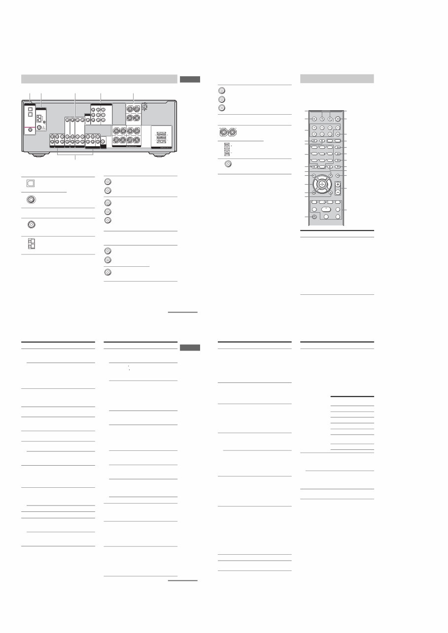
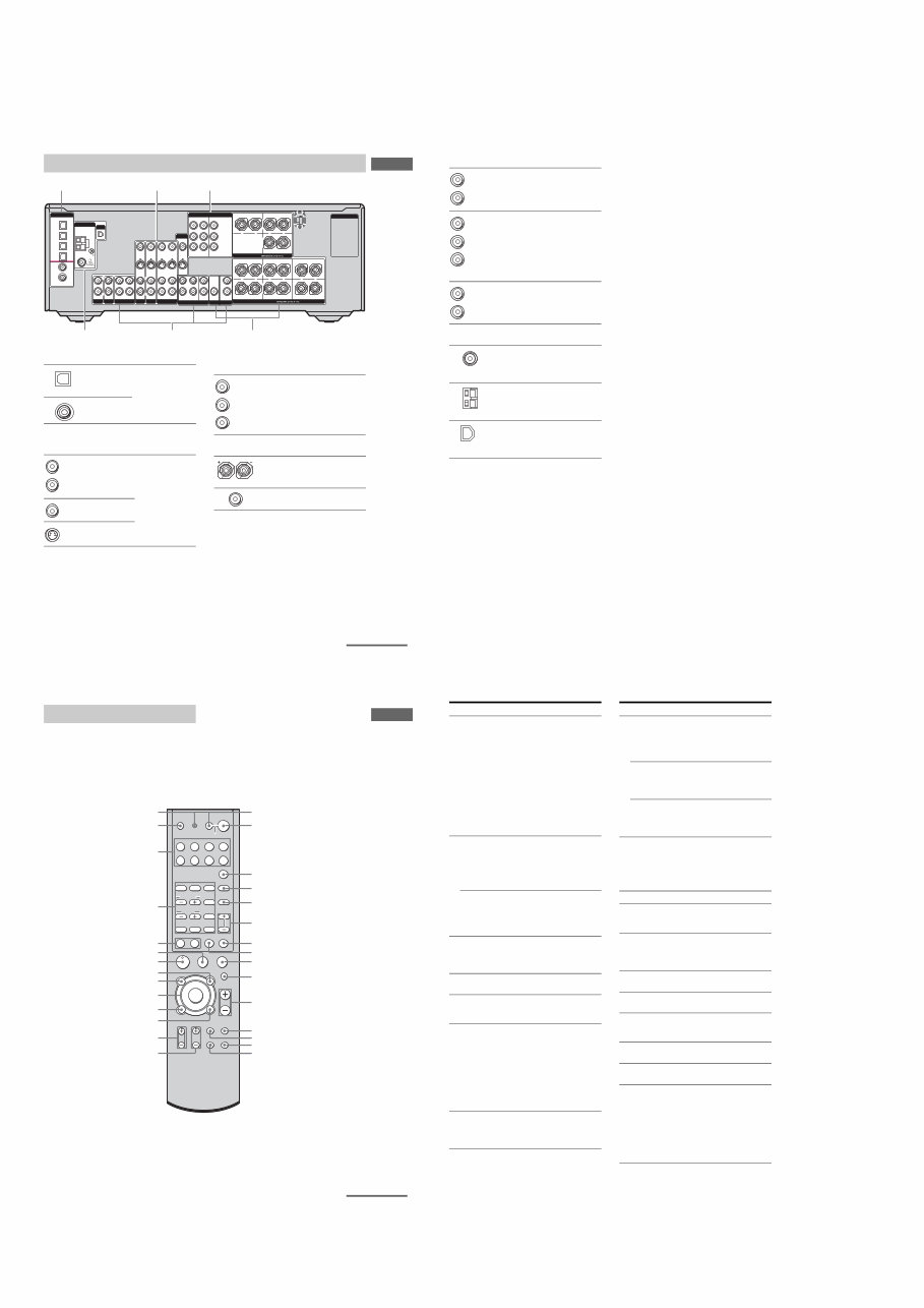
Rear panel
1 2
DIGITAL
OPTICAL
VIDEO 1
IN
VIDEO 2
IN
DVD
IN
COAXIAL
AM
ANTENNA
VIDEO 1 MULTI CH IN
FRONT
CENTER
SUB
WOOFER SURROUND
VIDEO IN
AUDIO IN
AUDIO
OUT
VIDEO IN VIDEO OUT
VIDEO 2
AUDIO IN
MD/TAPE SA-CD/CD
L
R
L
R
L
R
SUB
WOOFER
L
L
R
R
OUT IN IN
VIDEO IN
DVD
AUDIO IN AUDIO OUT
VIDEO OUT DVD
IN
VIDEO 2
IN
MONITOR
OUT
COMPONENT VIDEO
Y
ASSIGNABLE
PB/CB
/BñY
PR/CR
/RñY
MONITOR
CENTER
SURROUND BACK
SURROUND FRONT A
R R
L L
+ – + –
SPEAKERS
+ –
5 6
SPEAKERS
FRONT B
L R
L R
3
4
ADIGITAL INPUT section
OPTICAL
IN jack
Connects to a DVD
player, etc. The
COAXIAL jack
provides a better
quality of loud
sound (page 20,
22).
COAXIAL IN
jack
BANTENNA section
FM
ANTENNA
Connects to the
FM wire antenna
supplied with this
receiver (page 24).
AM
ANTENNA
Connects to the
AM loop antenna
supplied with this
receiver (page 24).
CAUDIO INPUT/OUTPUT section
AUDIO IN/
OUT jack
Connects to an MD
deck or CD player,
etc. (page 17).
MULTI
CHANNEL
INPUT jack
Connects to a
Super Audio CD
player or DVD
player which has
an analog audio
jack for 5.1
channel sound
(page 16).
DVIDEO/AUDIO INPUT/OUTPUT
section
AUDIO IN/
OUT jack
Connects the video
and audio jacks of
a VCR or a DVD
player (page 19,
20, 21, 22, 23).
VIDEO IN/
OUT jack*
White (L)
Red (R)
White (L)
Red (R)
Black
White (L)
Red (R)
Yellow
continued
10
GB
* You can watch the selected input image when you
connect the MONITOR OUT jack to a TV monitor
(page 19).
You can use the supplied remote RM-AAU005
to operate the receiver and to control the Sony
audio/video components that the remote is
assigned to operate (page 64).
ECOMPONENT VIDEO INPUT/
OUTPUT section
COMPONENT
VIDEO
INPUT/
OUTPUT
jack*
Connects to a DVD
player, TV, or a
satellite tuner. You
can enjoy high
quality image
(page 19, 21, 22).
FSPEAKER section
Connects to
speakers (page 14).
Connects to sub
woofer (page 14).
Green
Blue
Red
Remote commander
Name Function
A AV ?/1 Press to turn on or off the
Sony audio/video components
that the remote is assigned to
operate (page 64).
If you press ?/1 (B) at the
same time, it will turn off the
receiver and other
components (SYSTEM
STANDBY).
Note
The function of the AV ?/1
switch changes automatically
each time you press the input
buttons (W).
1 2 3
4 6
7 8
0/10 ENTER
9
SYSTEM STANDBY
TV/VIDEO
SLEEP
AUTO
CAL
AV
?/1
VIDEO 1 VIDEO 2 VIDEO 3 DVD
2CH A.F.D.
RETURN/EXIT
TV CH –
PRESET –
TV CH +
PRESET +
TUNING –
TV
TUNING +
REPLAY ADVANCE
MENU
MOVIE MUSIC
MEMORY DVD MENU
CLEAR
TOOLS DISPLAY MUTING
TV VOL
MASTER VOL
FM MODE
D.TUNING
D.SKIP
DUAL MONO
MD/TAPE SA-CD/CD TUNER AMP MENU
TV ?/1
?/1
-
F
G g
f
.
H m M
X x
< < >
5
>10/
wg
qg
qj
qk
qh
qf
ql
w;
wa
ws
wd
wf
qd
AV ?/1
(on/standby) switch
TV ?/1, ?/1
(on/standby) switch
1
3
2
5
6
7
8
q;
9
qs
qa
4
11
GB
Getting Started
Name Function
B TV ?/1 Press TV ?/1 and TV (M) at
the same time to turn the TV
on or off.
?/1 Press to turn the receiver on or
off.
To turn off all components,
press ?/1 and AV ?/1 (A) at
the same time (SYSTEM
STANDBY).
C AMP MENU Press to display the menu of
the receiver. Then, use the
control buttons to perform
menu operations.
D MOVIE,
MUSIC
Press to select sound fields
(MOVIE, MUSIC).
E DUAL MONO Press to select the language
you want during digital
broadcast.
F FM MODE Press to select FM monaural
or stereo reception.
G D.TUNING Press to enter direct tuning
mode.
D.SKIP Press to skip disc of the CD
player or DVD player (multi-
disc changer only).
H DVD MENU Press to display the menu of
the DVD player on the TV
screen. Then, use the control
buttons to perform menu
operations.
I ENTER Press to enter the value after
selecting a channel, disc or
track using the numeric
buttons.
MEMORY Press to store a station.
J MUTING Press to mute the sound.
K TV VOL
+
a)
/–
Press TV VOL +/– and TV
(M) at the same time to adjust
the TV volume level.
MASTER
VOL +
a)
/–
Press to adjust the volume
level of all speakers at the
same time.
Name Function
L ./> Press to skip tracks of the CD
player, DVD player, MD deck,
or tape deck.
REPLAY /
ADVANCE
Press to replay the previous
scene or fast forward the
current scene of the VCR or
DVD player.
m/M Press to
– search tracks in the forward/
backward direction of the
DVD player.
– fast forward/rewind of the
VCR, CD player, MD deck,
or tape deck.
H
a)
Press to start playback of the
VCR, CD player, DVD player,
MD deck, or tape deck.
X Press to pause playback or
recording of the VCR, CD
player, DVD player, MD deck,
or tape deck. (Also starts
recording with components in
recording standby.)
x Press to stop playback of the
VCR, CD player, DVD player,
MD deck, or tape deck.
TV CH +/– Press TV CH +/– and TV (M)
at the same time to select
preset TV channels.
PRESET +/– Press to select
– preset stations.
– preset channels of the VCR
or satellite tuner.
TUNING +/– Press to scan a station.
M TV Press TV and the button you
want at the same time to
activate the buttons with
orange printing.
N MENU Press to display the menus of
the VCR, DVD player, or
satellite tuner on the TV
screen. Then, use the control
buttons to perform menu
operations.
O RETURN/
EXIT O
Press to
– return to the previous menu.
– exit the menu while the
menu or on-screen guide of
the VCR, DVD player, or
satellite tuner is displayed on
the TV screen.
<
<
continued
12
GB
a)
The number 5, MASTER VOL +, TV VOL +, and
Hbuttons have tactile dots. Use the tactile dots as
references when operating the receiver.
Notes
Some functions explained in this section may not
work depending on the model.
The above explanation is intended to serve as an
example only. Therefore, depending on the
component, the above operation may not be
possible or may operate differently than described.
Name Function
P Control
buttons
After pressing AMP MENU
(C), DVD MENU (H), or
MENU (N), press the control
button V, v, B or b to select
the settings. When you press
DVD MENU or MENU, press
the control button to enter the
selection.
Q DISPLAY Press to select information
displayed on the TV screen of
the VCR, satellite tuner, CD
player, DVD player, or MD
deck.
R TOOLS Press to display options
applicable to the entire disc
(e.g. disc protection), recorder
(e.g. audio settings during
recording), or multiple items
on a list menu (e.g. erasing
multiple titles).
S -/-- Press -/-- and TV (M) at the
same time to select the
channel entry mode, either
one or two digits of the TV.
>10/x Press to select
– track numbers over 10 of the
VCR, satellite tuner, CD
player or MD deck.
– channel numbers of the
Digital CATV terminal.
CLEAR Press to
– clear a mistake when you
press the incorrect numeric
button.
– return to continuous
playback, etc. of the satellite
tuner or DVD player.
T Numeric
buttons
(number 5
a)
)
Press to
– preset/tune to preset
stations.
– select track numbers of the
CD player, DVD player or
MD deck. Press 0/10 to
select track number 10.
– select channel numbers of
the VCR or satellite tuner.
Press the numeric buttons and
TV (M) at the same time to
select the TV channels.
U A.F.D. Press to select A.F.D. mode.
V 2CH Press to select 2CH STEREO
mode.
Name Function
W Input buttons Press one of the buttons to
select the component you
want to use. When you press
any of the input buttons, the
receiver turns on. The buttons
are factory assigned to control
Sony components as follows.
You can change the button
assignments following the
steps in ìC hanging button
assignmentsî on page 64.
X TV/VIDEO Press TV/VIDEO and TV
(M) at the same time to select
the input signal (TV input or
video input).
SLEEP Press to activate the Sleep
Timer function and the
duration which the receiver
turns off automatically.
Y AUTO CAL Press to activate the Auto
Calibration function.
Button Assigned Sony
component
VIDEO 1 VCR (VTR mode 3)
VIDEO 2 VCR (VTR mode 2)
VIDEO 3 Not assigned
DVD DVD player
MD/TAPE MD deck
SA-CD/CD Super Audio CD/CD
player
TUNER Built-in tuner
7
STR-DG500/DG600
STR-DG600: US, CND MODEL
5
US
Getting Started
Description and location of parts
To remove the cover
Press PUSH.
When you remove the cover, keep it out of
reach from children.
Getting Started
Front panel
?/1
AUTO CAL MIC
SPEAKERS
(OFF/A/B/A+B)
PHONES
MEMORY/
ENTER
CATEGORY
MODE CATEGORY 2CH A.F.D. MOVIE MUSIC
MULTI CHANNEL DECODING
TUNING MODE DISPLAY INPUT MODE
INPUT SELECTOR TUNING –
MULTI CH IN DIRECT
MASTER VOLUME
VIDEO 3 IN/PORTABLE AV IN
VIDEO L AUDIO R DIGITAL(OPT)
PUSH
1 5 2 6 8 q; 4 3 9 7
qa qs ws qd qf w; wa qg qh qk ql qj
Name Function
A ?/1 Press to turn the receiver
on or off (page 30, 38, 39,
60, 85).
B SPEAKERS
(OFF/A/B/A+B)
Press to select OFF, A, B,
A+B of the front speakers
(page 32).
C TUNING MODE Press to select the tuning
mode (page 61, 63, 85).
D TUNING +/– Turn to scan a station
(page 61, 62).
continued
+
6
US
Name Function
E Display The current status of the
selected component or a
list of selectable items
appears here (page 7).
F MULTI
CHANNEL
DECODING
lamp
Lights up when multi
channel audio is decoded
(page 39).
G Remote sensor Receives signals from
remote commander.
H DISPLAY Press to select information
displayed on the display
(page 73).
I INPUT MODE Press to select the input
mode when the same
components are connected
to both digital and analog
jacks (page 71).
J MASTER
VOLUME
Turn to adjust the volume
level of all speakers at the
same time (page 36, 37,
38, 39).
K DIRECT Press to listen to high
quality analog sound
(page 59).
L MULTI CH IN Press to select the audio
directly from the
components connected to
the MULTI CH IN jacks
(page 37).
M INPUT
SELECTOR
Turn to select the input
source to playback (page
37, 38, 39, 59, 61, 63, 71,
72, 74).
N MOVIE,
MUSIC
Press to select sound fields
(MOVIE, MUSIC) (page
56).
O A.F.D. Press to select A.F.D.
mode (page 54).
P 2CH Press to select 2CH
STEREO mode (page 59,
60).
Name Function
Q CATEGORY +/– Press to select a category
(page 67).
R CATEGORY
MODE
Press to select the
category mode (page 67).
S MEMORY/
ENTER
Press to store a station or
enter the selection when
selecting the settings
(page 31).
T VIDEO 3 IN/
PORTABLE AV
IN jacks
To connect a camcorder or
video game (page 28, 37).
U AUTO CAL MIC
jack
Connects to the supplied
ECM-AC2 optimizer
microphone for the Auto
Calibration function (page
32).
V PHONES jack Connects to a headphone
(page 81).
7
US
Getting Started
About the indicators on the display
MEMORY
L C R
SL S SR
SBR SBL SB
SW
LFE SP A
SP B
CAT
STEREO MONO
A.DIRECT
D.RANGE EQ
NEO:6
SLEEP OPT COAX 96/24
DIGITAL EX ; DTS-ES ;PRO LOGIC IIx
qd qs qa qh
qj
qf qg
2 1 4 3 5 6 7 8 9
q;
Name Function
ASW Lights up when sub woofer
selection is set to “YES” (page
43) and the audio signal is
output from the SUB WOOFER
jack.
BLFE Lights up when the disc being
played back contains an LFE
(Low Frequency Effect)
channel and the LFE channel
signal is actually being
reproduced.
CSP A/SP B Lights up according to the
speaker system used. However,
these indicators do not light up
if the speaker output is turned
off or if a headphone is
connected.
D;DIGITAL
(EX)
Lights up when Dolby Digital
signals are input. “;
DIGITAL EX” lights up when
Dolby Digital Surround EX
signals are decoded.
Note
When playing a Dolby Digital
format disc, be sure that you
have made digital connections
and that INPUT MODE is not
set to “ANALOG” (page 71).
Name Function
E;PRO
LOGIC (II)/
(IIx)
Lights up when the receiver
applies Pro Logic processing to
2 channel signals in order to
output the center and surround
channel signals. “; PRO
LOGIC II” lights up when the
Pro Logic II Movie/Music/
Game decoder is activated.
“; PRO LOGIC IIx” lights up
when the Pro Logic IIx Movie/
Music/Game decoder is
activated. However, these
indicators do not light up if both
the center and surround
speakers are set to “NO” (page
43) and you select a sound field
using the A.F.D. button.
Note
Dolby Pro Logic IIx decoding
does not function for DTS
format signals or for signals
with a sampling frequency of
more than 48 kHz.
FDTS (-ES)/
(96/24)
Lights up when DTS signals are
input. “DTS-ES” lights up
when DTS-ES signals are input.
“DTS 96/24” lights up when the
receiver is decoding DTS 96
kHz/24 bit signals.
Note
When playing a DTS format
disc, be sure that you have made
digital connections and that
INPUT MODE is not set to
“ANALOG” (page 71).
GNEO:6 Lights up when DTS Neo:6
Cinema/Music decoder is
activated (page 55).
continued
8
US
HMEMORY Lights up when a memory
function, such as Preset
Memory (page 62), etc., is
activated.
IA.DIRECT Lights up when ANALOG
DIRECT is selected (page 59).
JPreset
station
indicators
Lights up when using the
receiver to tune in radio stations
you have preset. For details on
presetting radio stations, see
page 62.
KTuner
indicators
Lights up when using the
receiver to tune in radio stations
(page 60), etc.
LEQ Lights up when the equalizer is
activated (page 41).
MD.RANGE Lights up when dynamic range
compression is activated (page
41).
NCOAX Lights up when INPUT MODE
is set to “AUTO” and the source
signal is a digital signal being
input through the COAXIAL
jack, or when INPUT MODE is
set to “COAX IN” (page 71).
OOPT Lights up when INPUT MODE
is set to “AUTO” and the source
signal is a digital signal being
input through the OPTICAL
jack, or when INPUT MODE is
set to “OPT IN” (page 71).
PSLEEP Lights up when the sleep timer
is activated (page 73).
Name Function
QPlayback
channel
indicators
L
R
C
SL
SR
S
SBL
SBR
SB
The letters (L, C, R, etc.)
indicate the channels being
played back. The boxes around
the letters vary to show how the
receiver downmixes the source
sound (based on the speaker
settings).
Front Left
Front Right
Center (monaural)
Surround Left
Surround Right
Surround (monaural or the
surround components obtained
by Pro Logic processing)
Surround back left
Surround back right
Surround back (the surround
back components obtained by
6.1 channel decoding)
Example:
Recording format (Front/
Surround): 3/2.1
Output channel: When surround
speaker is set to “NO” (page 43)
Sound Field: A.F.D. AUTO
Name Function
L C R
SL SR
SW
Ver. 1.1
8
STR-DG500/DG600
9
US
Getting Started
Rear panel
3 2
DIGITAL
VIDEO 1
IN
VIDEO 2
IN
MD/
TAPE
IN
MD/
TAPE
OUT
DVD
IN
SA-CD/
CD
IN
COAXIAL
OPTICAL
ANTENNA
AM
XM
1
DVD
IN
VIDEO 2
IN
MONITOR
OUT
COMPONENT VIDEO AC OUTLET
Y
ASSIGNABLE
PB/CB
/BñY
PR/CR
/RñY
SURROUND BACK
R
L CENTER
+ – + –
SPEAKERS
SURROUND FRONT A
R R
L L
+ – + –
SPEAKERS
FRONT B
R
L
+ –
SA-CD/CD MD/TAPE
OUT
L
R
IN
L
R
AUDIO IN
VIDEO IN
DVD
AUDIO IN IN
AUX
IN
S-VIDEO
IN
VIDEO OUT
S-VIDEO
OUT
VIDEO IN
VIDEO 2
AUDIO IN
S-VIDEO
IN
VIDEO OUT
VIDEO 1
AUDIO OUT
S-VIDEO
OUT
VIDEO IN
S-VIDEO
IN
L
R
MONITOR
L
R
SURROUND
SUB
WOOFER
SUB
WOOFER
CENTER
FRONT
L
R
SURROUND
PRE OUT
L
R
MULTI CH IN
4 5 6
ADIGITAL INPUT/OUTPUT section
OPTICAL
IN/OUT jack
Connects to a DVD
player, etc. The
COAXIAL jack
provides a better
quality of loud sound
(page 18, 25, 27).
COAXIAL IN
jack
BVIDEO/AUDIO INPUT/OUTPUT
section
AUDIO IN/
OUT jack
Connects the video
and audio jacks of a
VCR or a DVD
player (page 24, 25,
26, 27, 28).
VIDEO IN/
OUT jack*
S-VIDEO IN/
OUT jack*
White (L)
Red (R)
Yellow
CCOMPONENT VIDEO INPUT/
OUTPUT section
COMPONENT
VIDEO INPUT/
OUTPUT jack*
Connects to a DVD
player, TV, or a
satellite tuner. You
can enjoy high
quality image
(page 24, 26, 27).
DSPEAKER section
Connects to
speakers (page 16).
Connects to sub
woofer (page 16).
Green
Blue
Red
continued
10
US
* You can watch the selected input image when you
connect the MONITOR OUT jack to a TV monitor
(page 24).
EAUDIO INPUT/OUTPUT section
AUDIO IN/
OUT jack
Connects to an MD
deck or CD player,
etc. (page 21).
MULTI
CHANNEL
INPUT jack
Connects to a
Super Audio CD
player or DVD
player which has
an analog audio
jack for 5.1
channel sound
(page 20).
PRE OUT
jack
Connects to an
external power
amplifier.
FANTENNA section
FM
ANTENNA
Connects to the FM
wire antenna
supplied with this
receiver (page 29).
AM
ANTENNA
Connects to the AM
loop antenna
supplied with this
receiver (page 29).
XM
ANTENNA
Connects to the XM
Connect-and-Play
antenna (not
supplied) (page 65).
White (L)
Red (R)
White (L)
Red (R)
Black
White (L)
Red (R)
11
US
Getting Started
You can use the supplied remote RM-AAP012
to operate the receiver and to control the Sony
audio/video components that the remote is
assigned to operate. You can also program the
remote to control non-Sony audio/video
components. For details, see “Programming
the remote” (page 75).
Remote commander
H X
m M
. >
-
VIDEO1 VIDEO2
RM SET UP
SYSTEM STANDBY SLEEP
TV ?/1 AV ?/1
VIDEO3 DVD
MD/TAPE SA-CD/CD TUNER AUX
MULTI CH
TOP MENU/
GUIDE AV MENU
MUTING
MASTER
VOL
DISPLAY
TV VOL TV CH
WIDE
AUTO
CAL
TV/
VIDEO
AMP
MENU
RETURN/EXIT
D.TUNING DISC ALT
ANT CLEAR SEARCH MODE
2CH A.F.D.
1 2 3
4 5 6
7 8 9
0/10 >10/11 12
MOVIE
SUBTITLE MEMORY ENTER
MUSIC
AUDIO ANGLE
TUNING
JUMP/
TIME
PRESET/
CH/D.SKIP
CATEGORY
MODE
DUAL
MONO
x
?/1
P
O
f
F
G g
CATEGORY
TV ?/1 (on/standby) switch
8
wl
ql
wa
wd
ws
w;
wg
wh
wj
wk
6
qa
5
7
q;
qs
qf
9
3
4
AV ?/1 (on/standby) switch
?/1 (on/standby) switch
1
2
qh
wf
qk
qj qd
qg
continued
12
US
Name Function
A AV ?/1 Press to turn on or off the
audio/video components that
the remote is programmed to
operate.
If you press ?/1 (B) at the
same time, it will turn off the
receiver and other
components (SYSTEM
STANDBY).
Note
The function of the AV ?/1
switch changes automatically
each time you press the input
buttons (wj).
B ?/1 Press to turn the receiver on or
off.
To turn off all components,
press ?/1 and AV ?/1 (A) at
the same time (SYSTEM
STANDBY).
SLEEP Press ALT (G) and then press
SLEEP to activate the Sleep
Timer function and the
duration which the receiver
turns off automatically.
C MULTI CH Press to select the audio
directly from the components
connected to the MULTI CH
IN jacks.
D MUSIC Press to select sound fields
(MUSIC).
E CATEGORY
MODE
Press to select the category
mode for XM Radio (page
67).
F PRESET/
CH/D.SKIP
+/–
Press to
– select preset stations.
– select preset channels of the
TV, VCR, satellite tuner,
Blu-ray disc recorder, or
hard disc recorder.
– skip disc of the CD player,
VCD player, DVD player,
MD deck, or LD player
(multi-disc changer only).
G ALT Press to light up the button. It
changes the remote key
function to activate the
buttons with orange printing.
Name Function
H -/-- Press to select the channel
entry mode, either one or two
digit of the TV, Blu-ray disc
recorder, hard disc recorder,
PSX, or satellite tuner.
DISC Press to select a disc directly
of the CD player or VCD
player (multi-disc changer
only).
SEARCH
MODE
Press to select the searching
mode or unit for search
(tracks, index, etc.) of the
DVD player.
I x Press to stop playback of the
VCR, CD player, VCD player,
LD player, DVD player, MD
deck, DAT deck, tape deck,
Blu-ray disc recorder, hard
disc recorder, or PSX.
J MUTING Press to mute the sound.
K MASTER
VOL +
a)
/–
Press to adjust the volume
level of all speakers at the
same time.
L AMP MENU Press to display the menu of
the receiver. Then, use the
control buttons to perform
menu operations.
M TV/VIDEO Press to select the input signal
(TV input or video input).
N AUTO CAL Press to activate the Auto
Calibration function.
O WIDE Press ALT (G) and then press
WIDE to select the wide
picture mode.
P TV CH +
a)
/– Press to select preset TV
channels.
Q TV VOL
+
a)
/–
Press to adjust the TV volume
level.
R RETURN/
EXIT O
Press to
– return to the previous menu.
– exit the menu while the
menu or on-screen guide of
the VCD player, LD player,
DVD player, Blu-ray disc
recorder, hard disc recorder,
PSX, or satellite tuner is
displayed on the TV screen.

9
STR-DG500/DG600
13
US
Getting Started
Name Function
S DISPLAY Press to select information
displayed on the TV screen of
the TV, VCR, VCD player,
LD player, DVD player, CD
player, MD deck, Blu-ray disc
recorder, hard disc recorder,
PSX, or satellite tuner.
T Control
buttons
After pressing AMP MENU
(L), TOP MENU/GUIDE
(U), or AV MENU (V),
press the control button V, v,
B or b to select the settings.
When you press TOP MENU/
GUIDE or AV MENU, press
the control button to enter the
selection.
U TOP MENU/
GUIDE
Press to display the
– DVD title.
– menu or on-screen guide of
the satellite tuner, Blu-ray
disc recorder, hard disc
recorder, or PSX on the TV
screen.
Then, use the control buttons
to perform menu operation.
V AV MENU Press to display the menus of
the VCR, DVD player,
satellite tuner, Blu-ray disc
recorder, hard disc recorder,
or PSX on the TV screen.
Then, use the control buttons
to perform menu operations.
W H
a)
Press to start playback of the
VCR, CD player, VCD player,
LD player, DVD player, MD
deck, DAT deck, tape deck,
Blu-ray disc recorder, hard
disc recorder, or PSX.
X X Press to pause playback or
recording of the VCR, CD
player, VCD player, LD
player, DVD player, MD
deck, DAT deck, tape deck,
Blu-ray disc recorder, hard
disc recorder, or PSX. (Also
starts recording with
components in recording
standby.)
Name Function
Y m/M Press to
– search tracks in the forward/
backward direction of the
CD player, VCD player,
DVD player, LD player, MD
deck, Blu-ray disc recorder,
hard disc recorder, or PSX.
– fast forward/rewind of the
VCR, DAT deck, or tape
deck.
D. TUNING Press to enter direct tuning
mode.
ANT Press ALT (G) and then press
ANT to select the signal to be
output from the antenna
terminal of the VCR or
satellite tuner (TV signal or
video signal).
CLEAR Press ALT (G) and then press
CLEAR to
– clear a mistake when you
press the incorrect numeric
button.
– return to continuous
playback, etc. of the CD
player, DVD player, Blu-ray
disc recorder, PSX, or
satellite tuner.
Z CATEGORY
+/–
Press to select the category
for XM Radio (page 67).
TUNING +/– Press to scan a station.
./> Press to skip tracks of the
VCR, CD player, VCD player,
LD player, DVD player, MD
deck, DAT deck, tape deck,
Blu-ray disc recorder, hard
disc recorder, or PSX.
2CH Press to select 2CH STEREO
mode.
A.F.D. Press to select A.F.D. mode.
MOVIE Press to select sound fields
(MOVIE).
DUAL MONO Press to select the language
you want during digital
broadcast.
continued
14
US
a)
The MASTER VOL +, TV VOL +, TV CH + and
Hbuttons have tactile dots. Use the tactile dots as
references when operating the receiver.
Notes
Some functions explained in this section may not
work depending on the model.
The above explanation is intended to serve as an
example only. Therefore, depending on the
component, the above operation may not be
possible or may operate differently than described.
The 12 button on the remote is not available for
receiver operation.
Name Function
AUDIO Press to change the sound to
Multiplex, Bilingual or Multi
channel TV sound of the TV,
VCR, DVD player, satellite
tuner, Blu-ray disc recorder,
hard disc recorder, or PSX.
ANGLE Press to select the viewing
angle or change the angles of
the DVD player or Blu-ray
disc recorder.
JUMP/TIME Press to
– toggle between the previous
and the current channels of
the satellite tuner, TV, or
Blu-ray disc recorder.
– show the time or display the
playing time of a disc, etc. of
the CD player, MD deck,
VCD player, or DVD player.
MEMORY Press MEMORY to store a
station.
SUBTITLE Press ALT (G) and then press
SUBTITLE to change the
subtitles of the DVD player.
ENTER Press ALT (G) and then press
ENTER to enter the value
after selecting a channel, disc
or track using the numeric
buttons.
Numeric
buttons
Press ALT (G) and then press
the numeric buttons to
– preset/tune to preset
stations.
– select track numbers of the
CD player, VCD player, LD
player, DVD player, MD
deck, DAT deck, or tape
deck. Press 0/10 to select
track number 10.
– select channel numbers of
the TV, VCR, satellite tuner,
Blu-ray disc recorder, hard
disc recorder, or PSX.
>10/11 Press ALT (G) and then press
>10/11 to select track
numbers over 10 of the CD
player, VCD player, LD
player, MD deck, tape deck,
TV, VCR, Blu-ray disc
recorder, hard disc recorder,
PSX, or satellite tuner.
Name Function
wj Input buttons Press one of the buttons to
select the component you
want to use. When you press
any of the input buttons, the
receiver turns on. The buttons
are factory assigned to control
Sony components as follows.
You can program the remote
to control non-Sony
components following the
steps in “Programming the
remote” on page 75.
wk TV ?/1 Press to turn the TV on or off.
wl RM SET UP Press to set up the remote.
Button Assigned Sony
component
VIDEO1 VCR (VTR mode 3)
VIDEO2 VCR (VTR mode 1)
VIDEO3 VCR (VTR mode 2)
DVD DVD player
MD/TAPE MD deck
SA-CD/CD Super Audio CD/CD
player
TUNER Built-in tuner
AUX Not assigned
10
STR-DG500/DG600
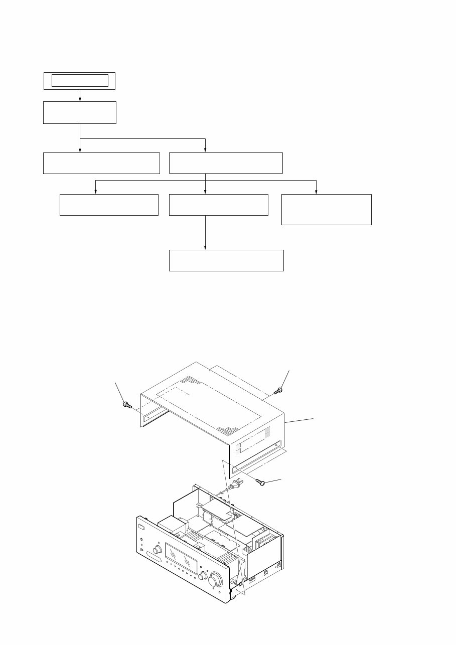
Note : This set can be disassemble according to the following sequence.
SECTION 2
DISASSEMBLY
2-1. CASE
2-1. CASE
(Page 10)
2-2. FRONT PANEL SECTION
(Page 11)
2-3. BACK PANEL SECTION
(Page 11)
SET
2-6. STANDBY BOARD
(Page 13)
2-4. DIGITAL BOARD
(Page 12)
2-7. SB AMP BOARD
(DG600)
(Page 13)
2-5. MAIN BOARD SECTION
(Page 12)
Note : Follow the disassembly procedure in the numerical order given.
1 two screws
(case 3 TP2)
2 two screws
(case 3 TP2)
3 two screws
(+BVTP 3 ⋅ 8)
4 case
You're Reading a Preview
What's Included?
Fast Download Speeds
Online & Offline Access
Access PDF Contents & Bookmarks
Full Search Facility
Print one or all pages of your manual
$28.99
Viewed 81 Times Today


Secure transaction
What's Included?
Fast Download Speeds
Online & Offline Access
Access PDF Contents & Bookmarks
Full Search Facility
Print one or all pages of your manual
$28.99
If you need a manual to assist with your DIY repair or have lost your copy, this is the perfect manual for you. These manuals are the same ones used by experts and technicians and are model-specific, not generic.
The manual will be made available instantly upon completion of payment, eliminating the need to wait for unreliable post. Additionally, you can print only the pages you need.


