

Denon AVR-1910 1620 1610 790 590 Service Manual & Repair Guide
What's Included?
Fast Download Speeds
Online & Offline Access
Access PDF Contents & Bookmarks
Full Search Facility
Print one or all pages of your manual
D&M Holdings lnc.
e
Copyright 2010 D&M Holdings Inc. All rights reserved.
WARNING: Violators will be prosecuted to the maximum extent possible.
SERVICE MANUAL
AV SURROUND RECEIVER
MODEL JP E3 E2 EK EA E1C E1K EUT
AVR-1910
3 3 3
AVR-1620
3
AVR-1610
3 3 3
AVR-790
3 3
AVR-590
3 3
Ver. 7
●
For purposes of improvement, specifications and design are subject to change without notice.
●
Please use this service manual with referring to the operating instructions without fail.
●
Some illustrations using in this service manual are slightly different from the actual set.
Please refer to the
MODIFICATION NOTICE.
S0183-1V06DM/DG1011
2
AVR-1910/1620/1610/790/590
Please heed the points listed below during servicing and inspection.
◎ Heed the cautions!
Spots requiring particular attention when servicing, such
as the cabinet, parts, chassis, etc., have cautions indicated
on labels or seals. Be sure to heed these cautions and the
cautions indicated in the handling instructions.
◎ Caution concerning electric shock!
(1) An AC voltage is impressed on this set, so touching in-
ternal metal parts when the set is energized could
cause electric shock. Take care to avoid electric shock,
by for example using an isolating transformer and
gloves when servicing while the set is energized, un-
plugging the power cord when replacing parts, etc.
(2)There are high voltage parts inside. Handle with extra
care when the set is energized.
◎ Caution concerning disassembly and
assembly!
Though great care is taken when manufacturing parts from
sheet metal, there may in some rare cases be burrs on the
edges of parts which could cause injury if fingers are
moved across them. Use gloves to protect your hands.
◎ Only use designated parts!
The set's parts have specific safety properties (fire resis-
tance, voltage resistance, etc.). For replacement parts, be
sure to use parts which have the same properties. In par-
ticular, for the important safety parts that are marked z on
wiring diagrams and parts lists, be sure to use the desig-
nated parts.
◎ Be sure to mount parts and arrange
the wires as they were originally!
For safety reasons, some parts use tape, tubes or other in-
sulating materials, and some parts are mounted away from
the surface of printed circuit boards. Care is also taken with
the positions of the wires inside and clamps are used to
keep wires away from heating and high voltage parts, so
be sure to set everything back as it was originally.
◎ Inspect for safety after servicing!
Check that all screws, parts and wires removed or discon-
nected for servicing have been put back in their original po-
sitions, inspect that no parts around the area that has been
serviced have been negatively affected, conduct an insu-
lation check on the external metal connectors and between
the blades of the power plug, and otherwise check that
safety is ensured.
(Insulation check procedure)
Unplug the power cord from the power outlet, disconnect
the antenna, plugs, etc., and turn the power switch on. Us-
ing a 500V insulation resistance tester, check that the in-
sulation resistance between the terminals of the power
plug and the externally exposed metal parts (antenna ter-
minal, headphones terminal, microphone terminal, input
terminal, etc.) is 1MΩ or greater. If it is less, the set must
be inspected and repaired.
Concerning important safety
parts
Many of the electric and structural parts used in the set
have special safety properties. In most cases these prop-
erties are difficult to distinguish by sight, and using re-
placement parts with higher ratings (rated power and
withstand voltage) does not necessarily guarantee that
safety performance will be preserved. Parts with safety
properties are indicated as shown below on the wiring dia-
grams and parts lists is this service manual. Be sure to re-
place them with parts with the designated part number.
(1) Schematic diagrams ... Indicated by the z mark.
(2) Parts lists ... Indicated by the z mark.
Using parts other than the designated
parts could result in electric shock, fires or
other dangerous situations.
SAFETY PRECAUTIONS
The following check should be performed for the continued protection of the customer and service technician.
LEAKAGE CURRENT CHECK
Before returning the unit to the customer, make sure you make either (1) a leakage current check or (2) a line to chassis
resistance check. If the leakage current exceeds 0.5 milliamps, or if the resistance from chassis to either side of the
power cord is less than 460 kohms, the unit is defective.
CAUTION
CAUTION
3
AVR-1910/1620/1610/790/590
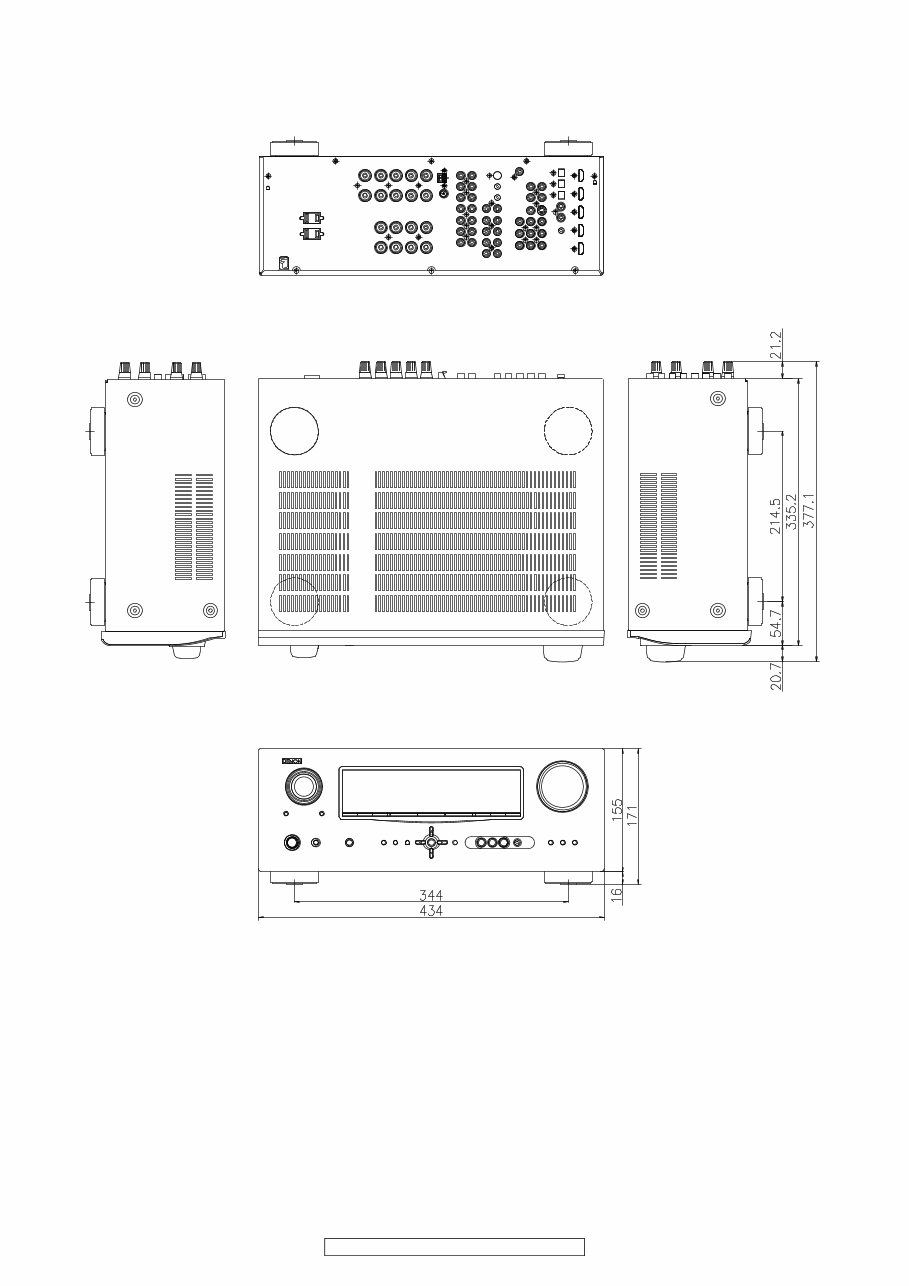
DIMENSION
AVR-1910 model
4
AVR-1910/1620/1610/790/590
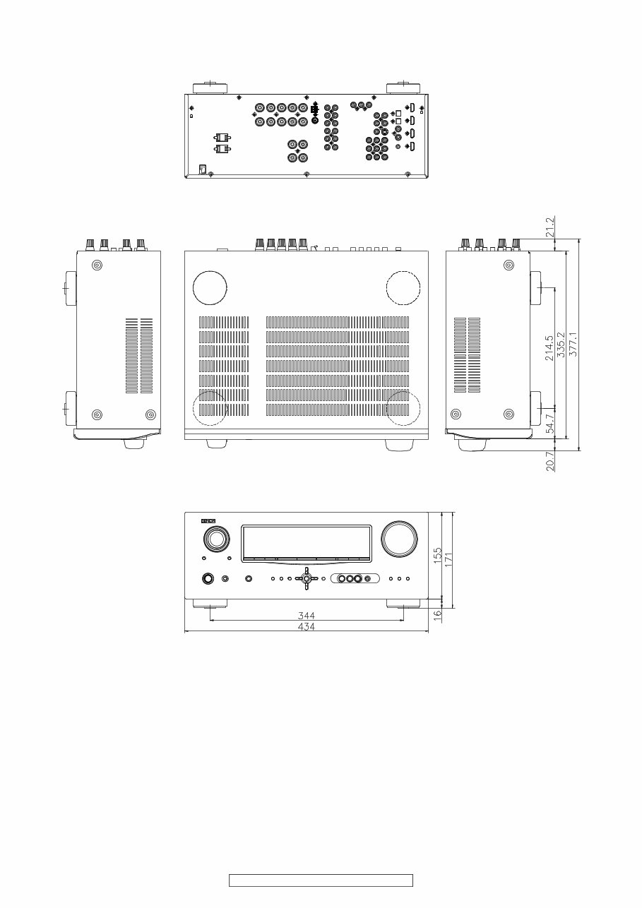
AVR-1610/1620 model
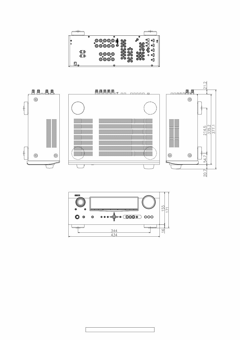
5
AVR-1910/1620/1610/790/590
AVR-790 model
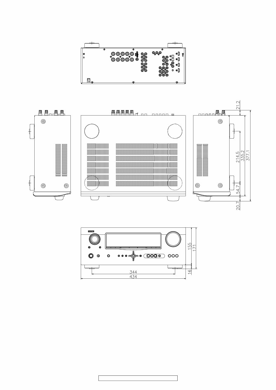
6
AVR-1910/1620/1610/790/590
AVR-590 model
7
AVR-1910/1620/1610/790/590
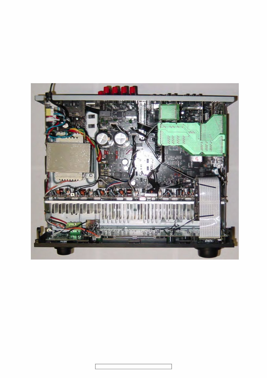
WIRE ARRANGEMENT
If wire bundles are untied or moved to perform adjustment or parts replacement etc., be sure to rearrange them neatly as
they were originally bundled or placed afterward.
Otherwise, incorrect arrangement can be a cause of noise
generation.
Wire arrangement viewed from the top
Back Panel side
Front Panel side
8
AVR-1910/1620/1610/790/590
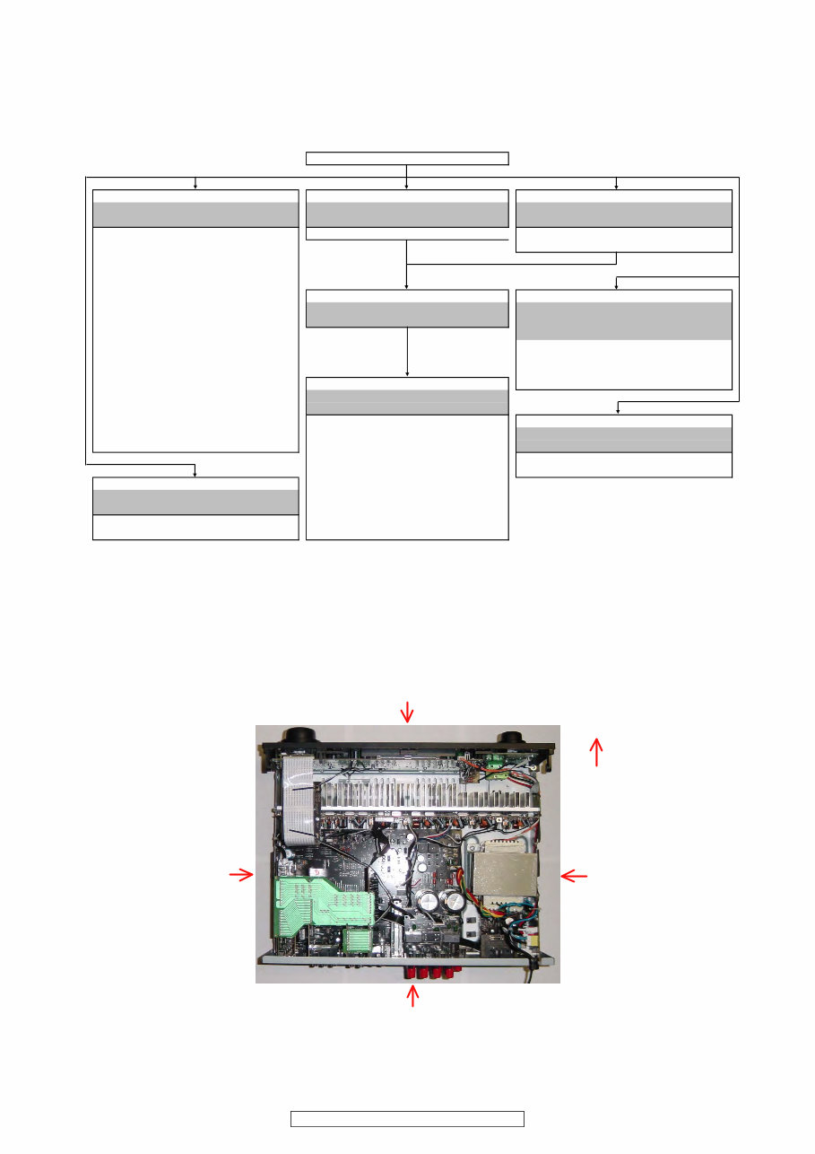
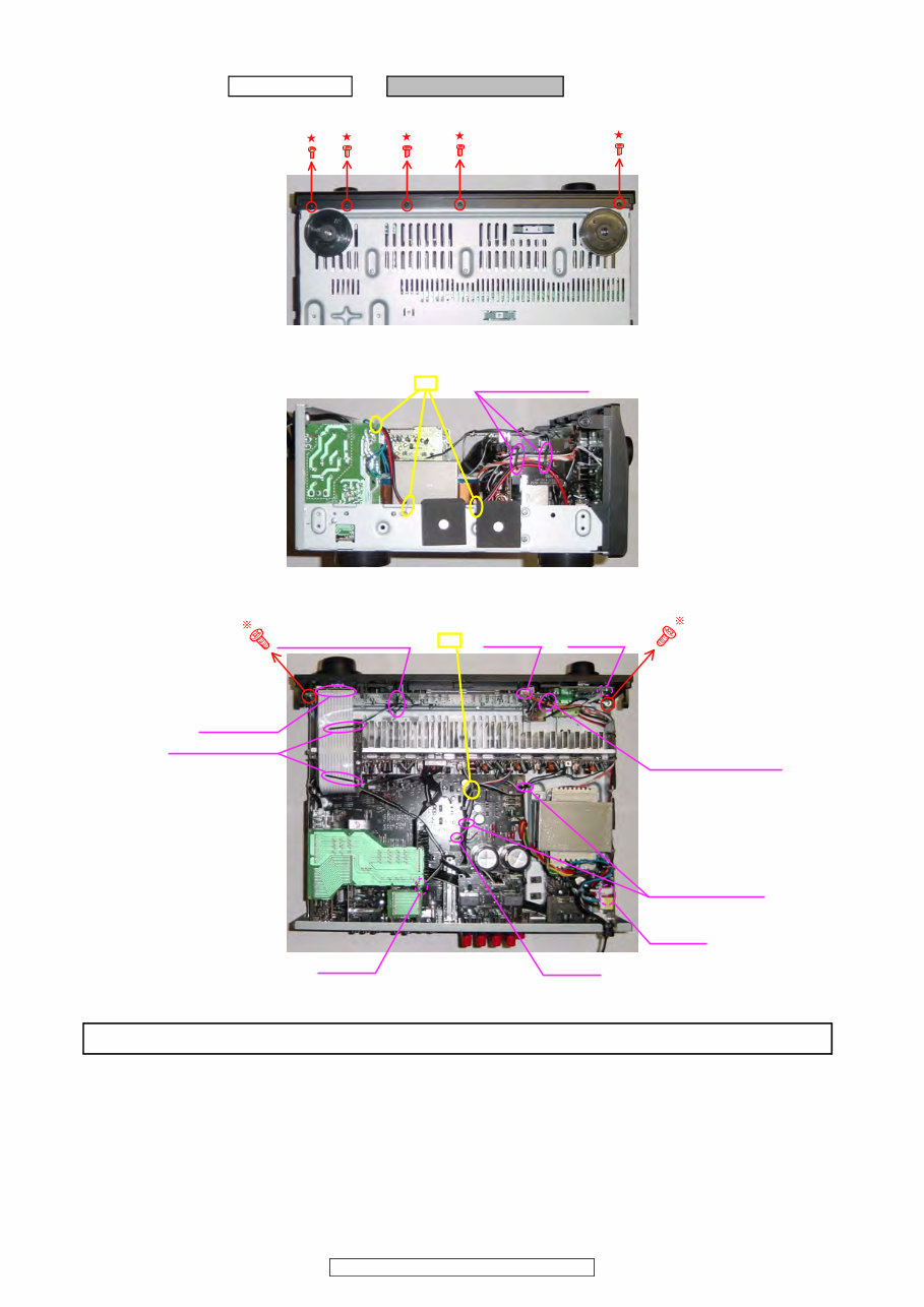
DISASSEMBLY
• Disassemble in order of the arrow of the figure of following flow.
• In the case of the re-assembling, assemble it in order of the reverse of the following flow.
• In the case of the re-assembling, observe "attention of assembling" it.
About the photos used for descriptions in the “DISASSEMBLY” section.
• The direction from which the photographs used herein were photographed is indicated at "Direction of photograph: ***" at
the left of the respective photographs.
• Refer to the table below for a description of the direction in which the photos were taken.
• Photographs for which no direction is indicated were taken from above the product.
• The photograph is AVR-1910.
CABINET TOP
PANEL FRONT ASSY PCB CNT1 PCB SPEAKER ASSY
Refer to "DISASSEMBLY 1.PANEL FRONT ASSY" Refer to "DISASSEMBL 2.PCB CNT1" Refer to "DISASSEMBLY 3.PCB SPEAKER ASSY"
and "EXPLODED VIEW" and "EXPLODED VIEW" and "EXPLODED VIEW"
PCB POWER SW ASSY PCB CNT1 (Ref. No. of EXPLODED VIEW : 71) PCB SPEAKER ASSY
(Ref. No. of EXPLODED VIEW : 9) (Ref. No. of EXPLODED VIEW : 63)
PCB FUNC ASSY
(Ref. No. of EXPLODED VIEW : 10)
PCB FRONT ASSY
(Ref. No. of EXPLODED VIEW : 11) CHASSIS BACK PCB POWER/POWER SUPPLY ASSY
PCB ENCORDER Refer to "DISASSEMBLY 4.CHASSIS BACK" Refer to "DISASSEMBLY
(Ref. No. of EXPLODED VIEW : 13) and "EXPLODED VIEW" 6.PCB POWER/POWER SUPPLY ASSY"
PCB HEAD PHONE ASSY and "EXPLODED VIEW"
(Ref. No. of EXPLODED VIEW : 14) PCB POWER SUPPLY ASSY
PCB V-AUX ASSY (Ref. No. of EXPLODED VIEW : 56)
(Ref. No. of EXPLODED VIEW : 21) PCB POWER ASSY
PCB MIC ASSY PCB MAIN ASSY (Ref. No. of EXPLODED VIEW : 57)
(Ref. No. of EXPLODED VIEW : 22) Refer to "DISASSEMBLY 5.PCB MAIN ASSY"
PCB CNT ENCORDER and "EXPLODED VIEW"
(Ref. No. of EXPLODED VIEW : 61) PCB MAIN ASSY TRANS MAIN
PCB SW (Ref. No. of EXPLODED VIEW : 50) Refer to "DISASSEMBLY 8.TRANS MAIN"
(Ref. No. of EXPLODED VIEW : 78) PCB INPUT ASSY and "EXPLODED VIEW"
(Ref. No. of EXPLODED VIEW : 51) TRANS MAIN
PCB VIDEO ASSY (Ref. No. of EXPLODED VIEW : 46)
PCB AMP ASSY (Ref. No. of EXPLODED VIEW : 53)
Refer to "DISASSEMBLY 7.PCB AMP ASSY" PCB DIGITAL ASSY
and "EXPLODED VIEW" (Ref. No. of EXPLODED VIEW : 54)
PCB AMP ASSY PCB HDMI ASSY
(Ref. No. of EXPLODED VIEW : 33) (Ref. No. of EXPLODED VIEW : 55)
The viewpoint of each photograph
(Photografy direction)
[View from above]
Front side
Direction of photograph: B
Direction of photograph: D Direction of photograph: C
Direction of photograph: A
9
AVR-1910/1620/1610/790/590
1. PANEL FRONT ASSY
(1) Remove the screws.
(2) Cut the wire clamp band, and loose the style pin.
(3) Cut the wire clamp band, then loose the style pin and Cord holder. Disconnect the connector wire and FFC Cable.
Proceeding : CABINET TOP → PANEL FRONT ASSY
View from bottom
Direction of photograph: D
Style pin : Loose cut
Cord holder : Loose
Cord holder : Loose
Style pin : Loose
CP1501
CP1300
Style pin : Loose
CP1001
CP1705
FFC Cable
CP1307 cut
Please refer to "EXPLODED VIEW" for the disassembly method of each P.W.B included in PANEL FRONT ASSY.
10
AVR-1910/1620/1610/790/590
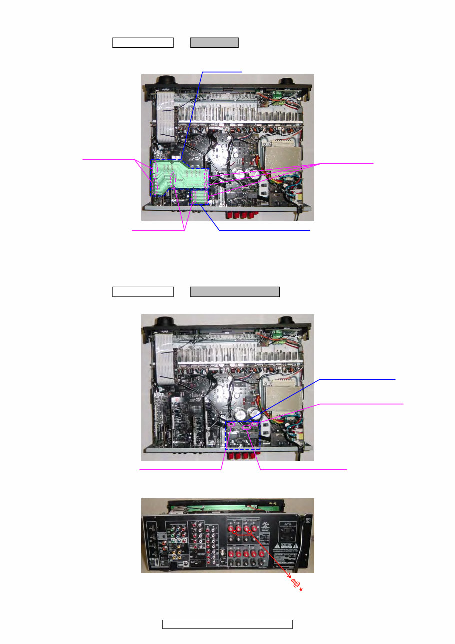
2. PCB CNT1
(1) Disconnect the connector board.
3. PCB SPEAKER ASSY
(1) Disconnect the connector wires.
(2) Remove the screws.
Proceeding : CABINET TOP → PCB CNT1
PCB CNT1
PCB CNT (1910/790 model)
Board to board
Board to board
Board to board
Proceeding : CABINET TOP → PCB SPEAKER ASSY
CP1001 (1910/790 model)
CN1309 (1910/790 model)
CP1002 (1910/790 model)
※ CP1003 (1610/1620/590/ model), CP1004 (1610/1620/590/ model)
PCB SPEAKER ASSY
Direction of photograph: A
You're Reading a Preview
What's Included?
Fast Download Speeds
Online & Offline Access
Access PDF Contents & Bookmarks
Full Search Facility
Print one or all pages of your manual
$31.99
Viewed 78 Times Today


Secure transaction
What's Included?
Fast Download Speeds
Online & Offline Access
Access PDF Contents & Bookmarks
Full Search Facility
Print one or all pages of your manual
$31.99
This service and repair manual for the Denon AVR 1910 1620 1610 790 590 Audio/Video Surround Receiver is an essential resource for both professional mechanics and DIY enthusiasts. It contains comprehensive technical information used by official Denon technicians and maintenance employees.
- Specifications
- Adjustments
- Disassembly Instructions
- Semiconductors
- Block Diagrams
- Level Diagram
- Printed Wiring Boards
- Wiring Diagrams
- Schematic Diagrams
- Exploded Views
- Parts List Catalog
This official service manual is provided in high resolution format and includes 154 pages of detailed information. It is available in English and can be accessed instantly after payment, allowing you to begin repairs promptly.


