SERVICE MANUAL PK 001631 HAMAMATSU, JAPAN 1.84K-686 Printed in Japan '99.09 CONTENTS SPECIFICATIONS ···································································· 3 CIRCUIT BOARD LAYOUT ······················································ 4 PANEL LAYOUT ······································································· 5 BLOCK DIAGRAM ···································································· 6 DISASSEMBLY PROCEDURE················································· 7 LSI PIN DESCRIPTION ·························································· 12 IC BLOCK DIAGRAM ····························································· 13 CIRCUIT BOARDS ································································· 14 TEST PROGRAM ··································································· 16 INITIALIZE ·············································································· 17 MIDI IMPLEMENTATION CHART ·········································· 18 MIDI DATA FORMAT······························································ 19 PARTS LIST OVERALL CIRCUIT DIAGRAM 19991001-140000
P-80 2 WARNING: CHEMICAL CONTENT NOTICE! The solder used in the production of this product contains LEAD. In addition, other electrical/electronic and/or plastic (where applicable) components may also contain traces of chemicals found by the California Health and Welfare Agency (and possibly other entities) to cause cancer and/or birth defects or other reproductive harm. DO NOT PLACE SOLDER, ELECTRICAL/ELECTRONIC OR PLASTIC COMPONENTS IN YOUR MOUTH FOR ANY REASON WHAT SO EVER! Avoid prolonged, unprotected contact between solder and your skin! When soldering, do not inhale solder fumes or expose eyes to solder/flux vapor! If you come in contact with solder or components located inside the enclosure of this product, wash your hands before handling food. IMPORTANT NOTICE This manual has been provided for the use of authorized Yamaha Retailers and their service personnel. It has been assumed that basic service procedures inherent to the industry, and more specifically Yamaha Products, are already known and understood by the users, and have therefore not been restated. WARNING: Failure to follow appropriate service and safety procedures when servicing this product may result in personal injury, destruction of expensive components and failure of the product to perform as specified. For these reasons, we advise all Yamaha product owners that all service required should be performed by an authorized Yamaha Retailer or the appointed service representative. IMPORTANT: This presentation or sale of this manual to any individual or firm does not constitute authorization, certification, recognition of any applicable technical capabilities, or establish a principal-agent relationship of any form. The data provided is belived to be accurate and applicable to the unit(s) indicated on the cover. The research engineering, and service departments of Yamaha are continually striving to improve Yamaha products. Modifications are, therefore, inevitable and changes in specification are subject to change without notice or obligation to retrofit. Should any discrepancy appear to exist, please contact the distributor's Service Division. WARNING: Static discharges can destroy expensive components. Discharge any static electricity your body may have accumulated by grounding yourself to the ground bus in the unit (heavy gauge black wires connect to this bus.) IMPORTANT: Turn the unit OFF during disassembly and parts replacement. Recheck all work before you apply power to the unit. WARNING Components having special characteristics are marked and must be replaced with parts having specification equal to those originally installed. LITHIUM BATTERY HANDLING This product uses a lithium battery for memory back-up. WARNING: Lithium batteries are dangerous because they can be exploded by improper handling. Observe the following precautions when handling or replacing lithium batteries. Leave lithium battery replacement to qualified service personnel. Always replace with batteries of the same type. When installing on the PC board by soldering, solder using the connection terminals provided on the battery cells. Never solder directly to the cells. Perform the soldering as quickly as possible. Never reverse the battery polarities when installing. Do not short the batteries. Do not attempt to recharge these batteries. Do not disassemble the batteries. Never heat batteries or throw them into fire. ADVARSEL! Lithiumbatteri-Eksplosionsfare ved fejlagtig håndtering. Udskiftning må kun ske med batteri af samme fabrikat og type. Levér det brugte batteri tilbage til leverandøren. VARNING Explosionsfara vid felaktigt batteribyte. Använd samma batterityp eller en ekvivalent typ som rekommenderas av apparattillverkaren. Kassera använt batteri enligt fabrikantens instruktion. VAROITUS Paristo voi räjähtää, jos se on virheellisesti asennettu. Vaihda paristo ainoastaan laitevalmistajan suosittelemaan tyyppiin. Hävitä käytetty paristo valmistajan ohjeiden mukaisesti. The following information complies with Dutch Official Gazette 1995. 45; ESSENTIALS OF ORDER ON THE COLLECTION OF BATTERIES. • Please refer to the diassembly procedure for the removal of Back-up Battery. • Leest u voor het verwijderen van de backup batterij deze beschrijving.
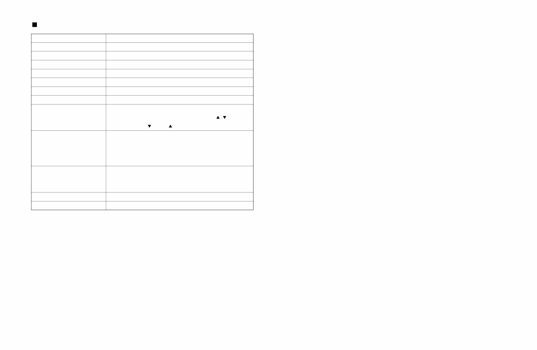
SPECIFICATIONS P-80 3 KEYBOARD POLYPHONY VOICE SELECTORS REVERB EFFECT TOUCH SENSITIVITY SONG CONTROLS PEDAL CONTROL OTHER CONTROLS JACKS/CONNECTORS POWER SUPPLY DIMENTIONS (W x D x H) WEIGHT 88 KEYS (A-1 — C7) 64 NOTES MAX. 12 voices + Variation for each voice ROOM, HALL 1, HALL 2, STAGE CHORUS, SYMPHONIC, TREMOLO, DELAY HARD, MEDIUM, SOFT, FIXED PRESET, TRACK 1, 2, START/STOP, REC SUSTAIN MASTER VOLUME, BRILLIANCE, DEMO, TRANSPOSE, SPLIT, METRONOME START/STOP, TEMPO/FUNCTION# / , FUNCTION, –/NO , +/YES , LED Display OUT PUT: L and R Pin Jacks, L/L+R and R Phone Jacks (Output impedance 600 Ω), MIDI IN/OUT, HOST SELECT, TO HOST, PHONES x 2, SUSTAIN, DC IN 12 V Yamaha PA-3B power adaptor Rated Voltage DC12 V Rated Current 700 mA 1347 x 285 x 128 mm (53" x 11-1/4" x 5") 16.8 kg (37 lbs.)
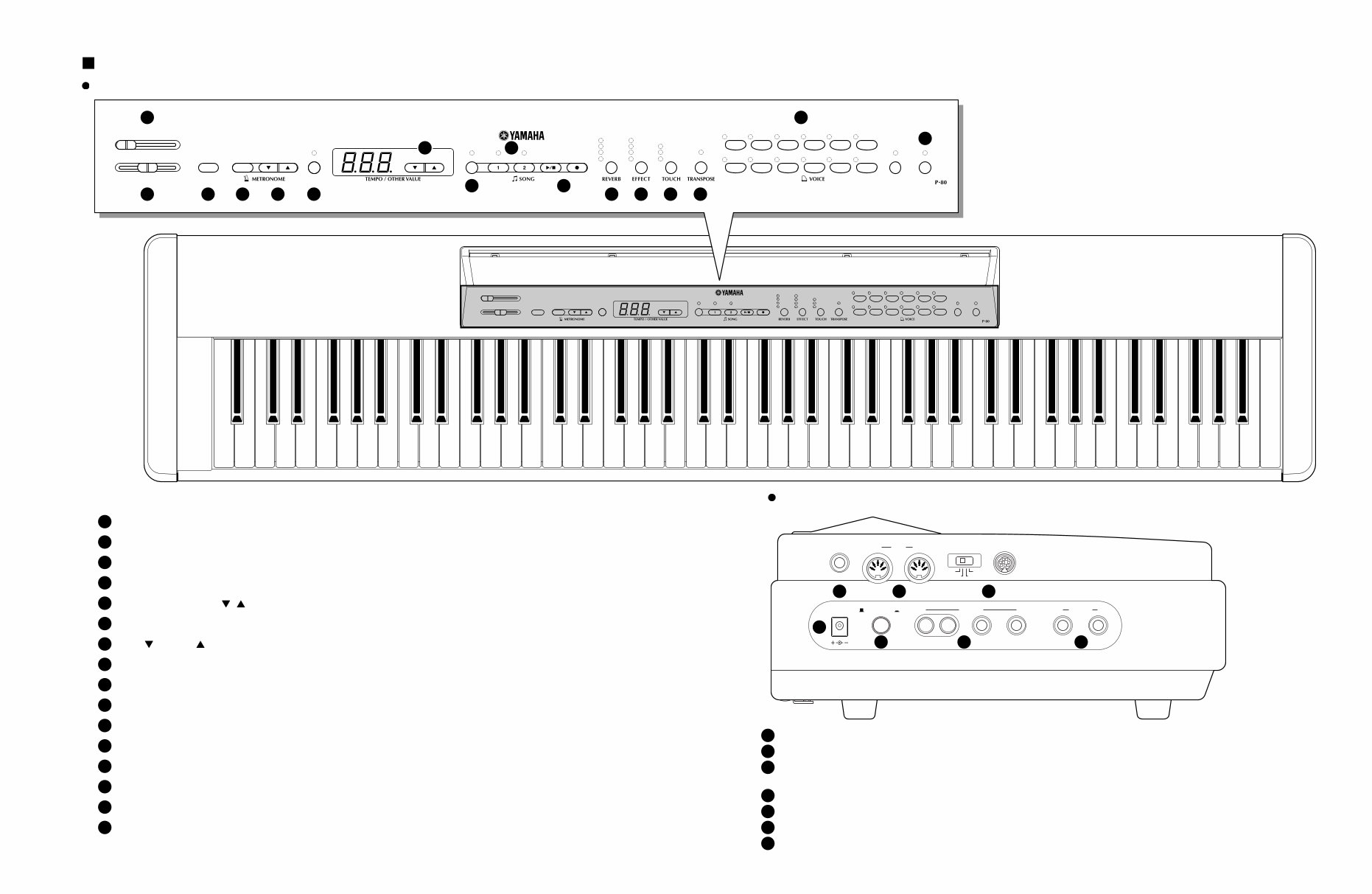
PANEL LAYOUT P-80 5 MASTER VOLUME MIN MAX BRILLIANCE MELLOW BRIGHT DEMO START/ STOP TEMPO/ FUNCTION# FUNCTION – / NO + / YES PRESET TRACK START/ STOP REC ROOM HALL 1 HALL 2 STAGE SYMPHONIC CHORUS TREMOLO DELAY HARD MEDIUM SOFT ON GRAND PIANO CLASSICAL PIANO JAZZ PIANO ROCK PIANO E. PIANO 1 E. PIANO 2 HARPSI- CHORD STRINGS PIPE ORGAN CHURCH ORGAN JAZZ ORGAN BASS VARIATION SPLIT ELECTRONIC PIANO B0 A0 G0 F0 E0 D0 C0 B-1 A-1 C1 D1 E1 F1 G1 A1 B1 C2 D2 E2 F2 G2 A2 B2 C3 D3 E3 F3 G3 A3 B3 C4 D4 E4 F4 G4 A4 B4 C5 D5 E5 F5 G5 A5 B5 C6 D6 E6 F6 G6 A6 B6 C7 MASTER VOLUME MIN MAX BRILLIANCE MELLOW BRIGHT DEMO START/ STOP TEMPO/ FUNCTION# FUNCTION – / NO + / YES PRESET TRACK START/ STOP REC ROOM HALL 1 HALL 2 STAGE SYMPHONIC CHORUS TREMOLO DELAY HARD MEDIUM SOFT ON GRAND PIANO CLASSICAL PIANO JAZZ PIANO ROCK PIANO E. PIANO 1 E. PIANO 2 HARPSI- CHORD STRINGS PIPE ORGAN CHURCH ORGAN JAZZ ORGAN BASS VARIATION SPLIT ELECTRONIC PIANO SUSTAIN IN MIDI OUT HOST SELECT TO HOST MIDI Mac PC-2 PC-1 DC IN 12V STANDBY / ON OUTPUT PHONES L R L /L+R R 1 1 5 6 7 2 3 4 15 16 2 3 4 5 6 11 12 13 14 8 10 7 9 [MASTER VOLUME] Control 1 [DC IN 12V] Jack 1 [STANDBY/ON] Switch 2 OUTPUT Jacks : L and R Pin jacks, L/L+R and R Phone Jacks 3 PHONES Jacks 4 SUSTAIN Jack 5 MIDI IN, and OUT Connectors 6 TO HOST Connector & HOST SELECT Switch 7 [BRILLIANCE] Control 2 [DEMO] Button 3 METRONOME [START/STOP] Button 4 [FUNCTION] Button 6 SONG [PRESET] Button 8 TRACK [1] and [2] Buttons 9 SONG [START/STOP] and [REC] Buttons 10 [REVERB] Button 11 [EFFECT] Button 12 [TOUCH] Button 13 [TRANSPOSE] Button 14 VOICE Buttons & [VARIATION] Button 15 [SPLIT] Button 16 [–/NO ], [+/YES ] Buttons 7 [TEMPO/FUNCTION# , ] Buttons 5 Control panel Side panel
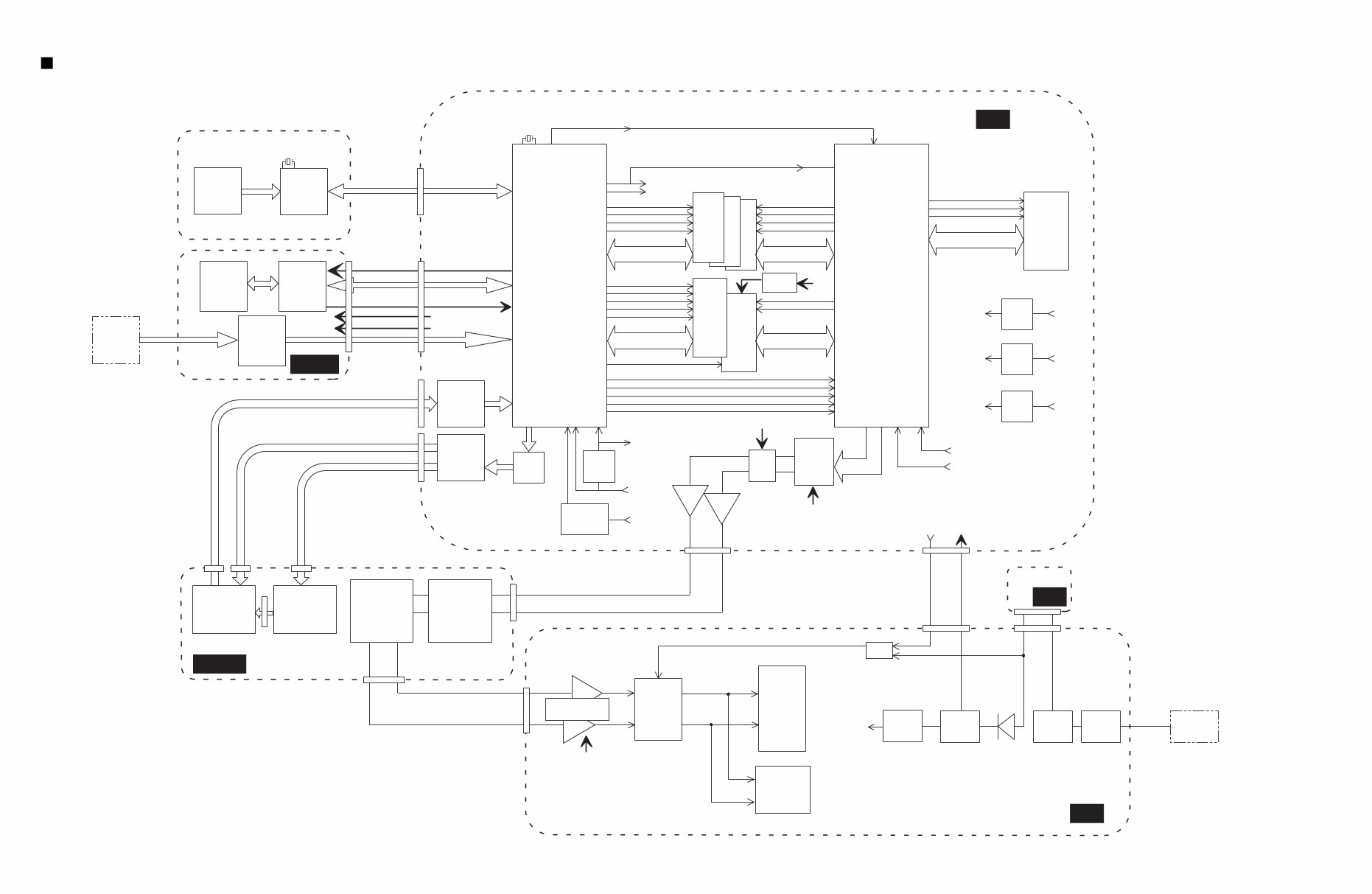
BRILLIANS 1M SRAM 16bit 4MHz CN3 8.4672MHz SWX00B +3.3 V REG. +5D RES. LSIIC MUTE 8M ROM MAIN 16bit COE CWR CUB CLB CS0 SOE PRD PCS PWR +3.3D +3.3D +5D 4M DRAM DSP 16bit IC3 CWE SRAS DATA BUS,ADDRESS BUS CMA(1-8),CMD(0-15) DATA BUS,ADDRESS BUS CMA(1-19),CMD(0-15) DATA BUS,ADDRESS BUS SMA(0-20),SMD(0-15) DATA BUS,ADDRESS BUS SMA(1-20),SMD(0-15) DATA BUS,ADDRESS BUS PAD(0-2),PDT(0-15) SCAS CS1 A23(CS0) A22(CS1) A21(CS2) SOE A23(CS0) A22(CS1) A21(CS2) CS2 MIX0 MELO OSCLKO SYO MIXI MELI1 RFCLKI SYI RES. MCLK AN0 1MHz Mute relay Mute +5V REG. +B +5A +9V REG. +B +9A +5V SW-REG. +B +5D Headphone amp. NJM2073D POST LPF AUX OUT jacks (x 2) 3-8 DEC Initial clear +5D +B PHONES jacks (x 2) I/V Switches LEDs MUTE AND MUTE2 +3.3D +5D MASTER VOLUME Line filter STANDBY Electrolytic cap. +9V REG. +9V +5A +9A +9V PA-3B AC adapter BACKUP SC 0.1F circuit +5D KEYBOARD JACK PANEL CN1 CN6 CN2 CN1 CN201 CN202 CN301 CN302 CN1 CN4 CN3 CN2 CN3 CN5 CN1 IC1 IC1 IC13, IC22 IC13, IC22 7 1 6 3 CN2 IC8 SWX00B IC7 IC9 IC1 IC5 MIDI HOST jacks GHD KSN2 Conversion Circuit SUSTAIN jack Pedal FC-4 TR Array TR Array Protector switch 1.85A M SW DM DAC PCM69AU IC10 IC2 32M ROM WAVE 1 IC11 2 IC14 3 28CA1-8814620 BLOCK DIAGRAM P-80 6
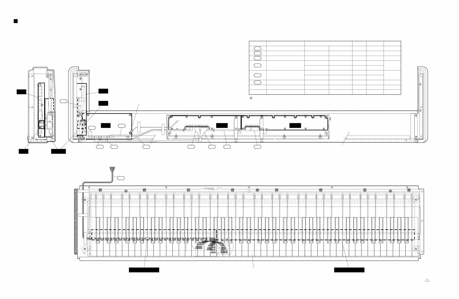
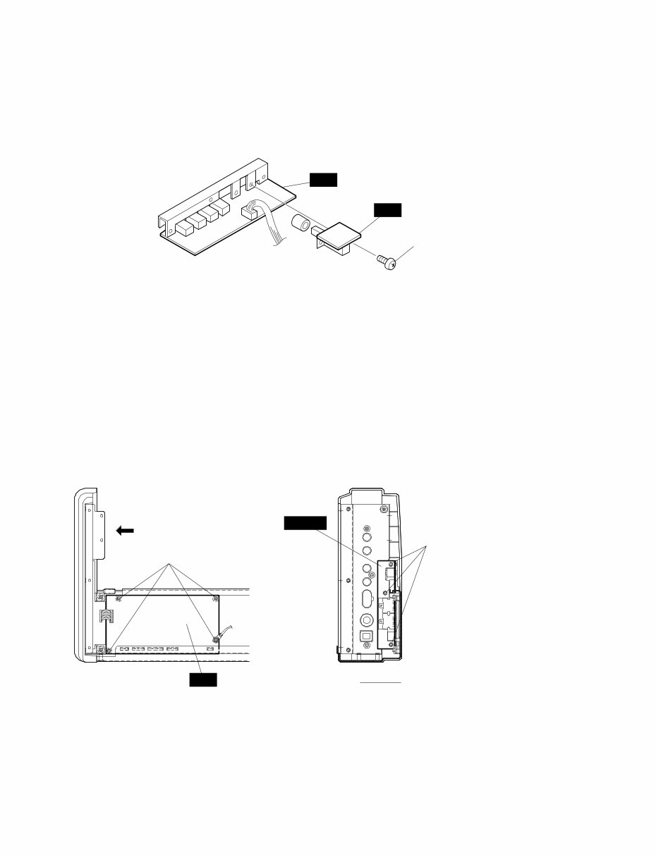
M A A view Upper case assembly (Fig. 3) [250A] [250]: Bind Head Tapping Screw-B 3.0X6 MFZN2Y (EP600130) DISASSEMBLY PROCEDURE P-80 7 1. Upper Case Assembly 1-1 Remove the twelve (12) screws marked [60A] located on the bottom board. (Fig.1) 1-2 Lift the keyboard assembly from the front and take it out of the upper case assembly. (Fig.2) 2. M Circuit Board 2-1 Remove the upper case assembly. (See Procedure 1.) 2-2 Remove the three (3) screws marked [250A]. The M circuit board can then be removed. (Fig.3) Bottom side [60A] [60A] [60A] [60A] (Fig. 1) (Fig. 2) [60]: Bind Head Screw 4.0X6 MFZN2BL (EG340340)
P-80 8 SW M [250B] (Fig. 4) [250]: Bind Head Tapping Screw-B 3.0X6 MFZN2Y (EP600130) 3. SW Circuit Board 3-1 Remove the upper case assembly. (See Procedure 1.) 3-2 Remove the M circuit board. (See Procedure 2.) 3-3 Remove the two (2) screws marked [250B]. The SW circuit board can then be removed. (Fig.4) 4. DM Circuit Board 4-1 Remove the upper case assembly. (See Procedure 1.) 4-2 Remove the M circuit board. (See Procedure 2.) 4-3 Remove the four (4) screws marked [250C]. The DM circuit board can then be removed. (Fig.5) 5. JACK Circuit Board 5-1 Remove the upper case assembly. (See Procedure 1.) 5-2 Remove the M circuit board. (See Procedure 2.) 5-3 Remove the DM circuit board. (See Procedure 4.) 5-4 Remove the three (3) screws marked [250D]. The JACK circuit board can then be removed. (Fig.5) 6. PNL Circuit Board 6-1 Remove the upper case assembly. (See Procedure 1.) 6-2 Remove the two (2) screws marked [250E] and the screw marked [260A]. The angle bracket can then be removed. (Fig.6) 6-3 Remove the seven (7) screws marked [250F]. The PNL circuit board can then be removed. (Fig.6) JACK B B view [250C] (Fig. 5) [250D] [250]: Bind Head Tapping Screw-B 3.0X6 MFZN2Y (EP600130) DM
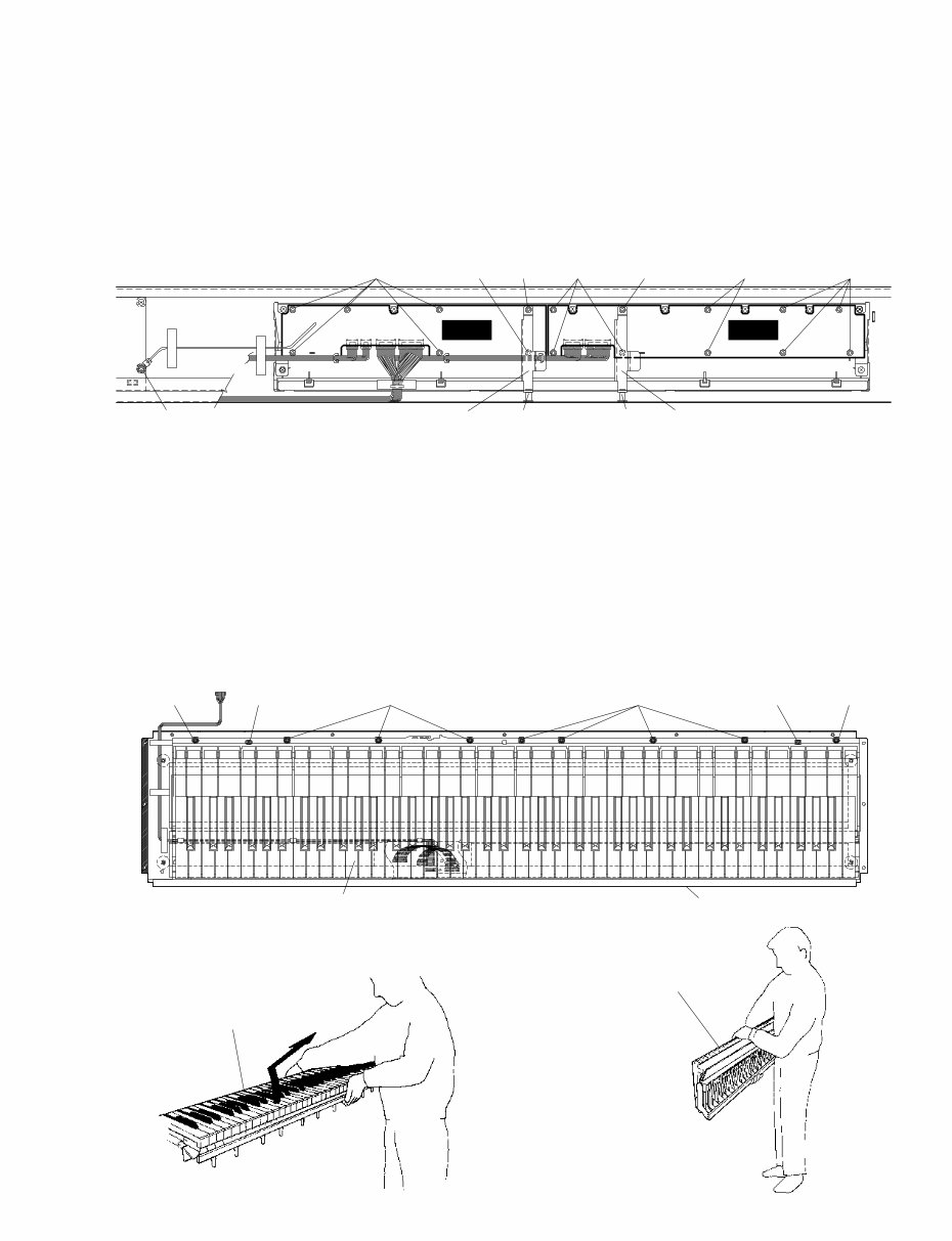
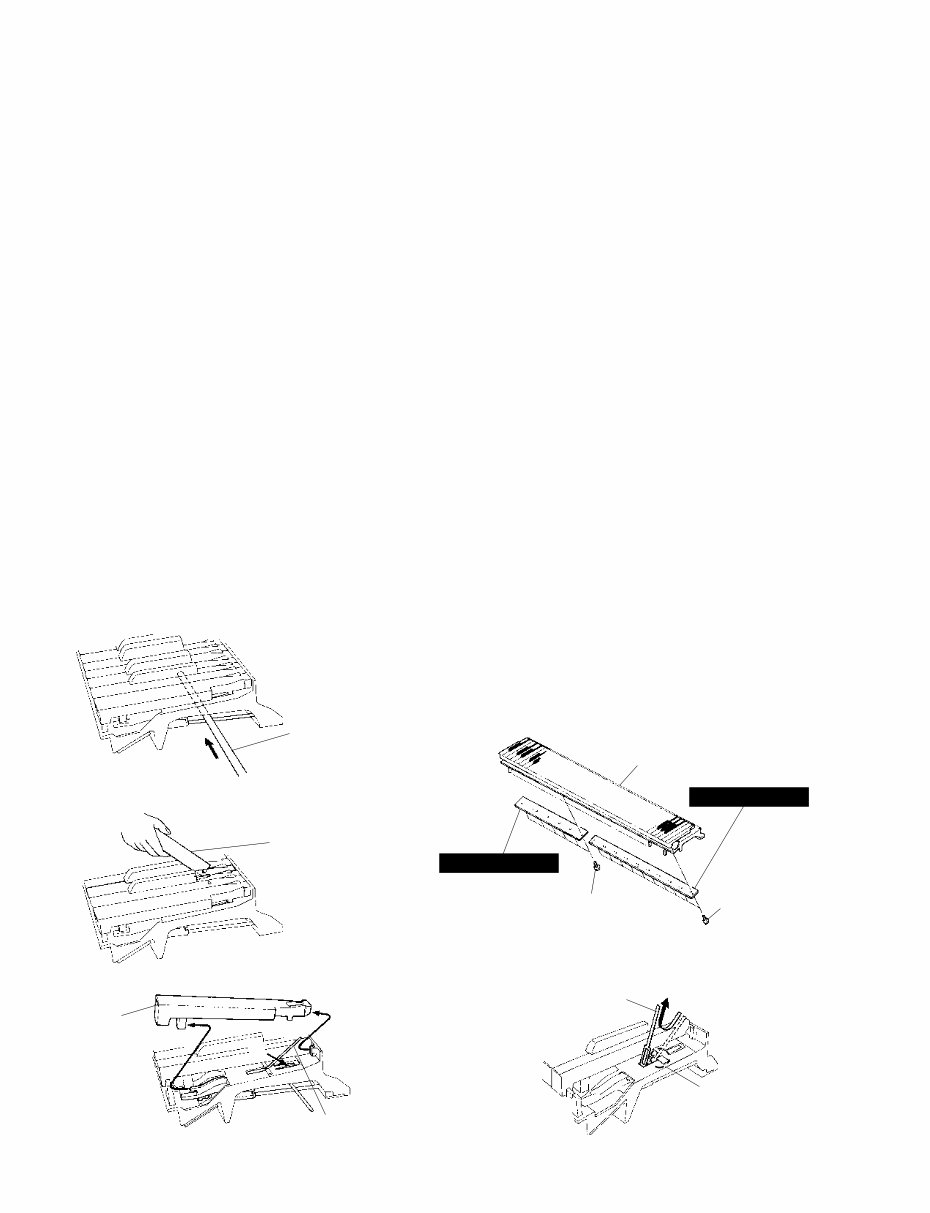
(Fig. 7) (Fig. 8) (Fig. 9) [40] [40] Keyboard assembly Keyboard assembly Keyboard assembly Bottom side [40] [40] [60B] [60B] [40]: Pan Head Screw PW 5.0X16 MFZN2BL (V4439900) [60]: Bind Head Screw 4.0X6 MFZN2BL (EG340340) P-80 9 8. Keyboard Assembly 8-1 Remove the upper case assembly. (See Procedure 1.) 8-2 Remove the nine (9) screws marked [40] and the two (2) screws marked [60B]. The keyboard assembly can then be removed. (Fig.7) * When you take the keyboard assembly out of the bottom board, hold the middle of it. Lift the keyboard assembly from the front and the take it out of the bottom board as shown in the figures. (Fig. 8, Fig.9) PNL PNR (Fig. 6) [250F] [250E]X2 [250G]X2 [250H] [250H] [260B] [260A] [250H] [250F] [250F] Angle Bracket, Panel Angle Bracket, Panel [250]: Bind Head Tapping Screw-B 3.0X6 MFZN2Y (EP600130) [260]: Bind Head Tapping Screw-B 3.0X8 MFZN2BL (EP600190) 7. PNR Circuit Board 7-1 Remove the upper case assembly. (See Procedure 1.) 7-2 Remove the two (2) screws marked [250G] and the screw marked [260B]. The angle bracket can then be removed. (Fig.6) 7-3 Remove the nine (9) screws marked [250H]. The PNR circuit board can then be removed. (Fig.6)
(Fig. 12) (Fig. 13) (Fig. 14) Thin metal plate etc (Fig. 10) (Fig. 11) Insert a round stick before removing circuit boards. Rod (TX000670) [260C] Keyboard assembly [260D] GH-D SW(H) GH-D SW(L) [260]: Bind Head Tapping Screw-P 3.0X10 MFZN2Y (VT413400) White key Spring [A] Spring Hook P-80 10 9. Disassembling the Keyboard * After inserting a round stick (Rod:TX000670) between the frame and the keys, remove the circuit boards. (Fig.10) 9-1 Remove the keyboard assembly out of the bottom board. (See Procedure 8.) 9-2 GH-D SW (L) Circuit Board Remove the seven (7) screws marked [260C]. The GH-D SW (L) circuit board can then be removed. (Fig.11) 9-3 GH-D SW (H) Circuit Board Remove the ten (10) screws marked [260D]. The GH-D SW (H) circuit board can then be removed. (Fig.11) * Keys can be removed without removing the circuit boards. * After removing the GH-D SW (L) and GH-D SW (H) circuit boards, and the rubbers can then be removed. 9-4 White key Insert a thin plate between the white keys, near the triangle mark around the fulcrum of the key, and press down the stopper marked [A] to remove the key. (Fig.12, Fig.13) * Take care not to damage the key spring when removing a key. * A black key can be removed after the white keys on either side have been removed. 9-5 After a key has been removed, push a key spring down once to take it out of the hook. (Fig.14) Place the keyboard assembly upside-down and peel the stopper away. Then hammer of the white key can then be removed. (Fig.15)
This is a comprehensive service manual containing specifications, parts list, exploded views, circuit board diagrams, and more. It is an invaluable resource for both professional mechanics and DIY enthusiasts.
Whether you want to modify, circuit bend, fix broken features, restore the appearance, or revive your Yamaha product, this manual provides the necessary guidance. Additionally, it offers insights into accessing the secret test mode in most products.
The manual is extensive and visually impressive, covering various topics commonly found in Yamaha service manuals:
SPECIFICATIONS
PANEL LAYOUT
CIRCUIT BOARD LAYOUT
BLOCK DIAGRAM
DISASSEMBLY PROCEDURE
LSI PIN DESCRIPTION
IC BLOCK DIAGRAM
CIRCUIT BOARDS
INSPECTION
MIDI IMPLEMENTATION CHART
OVERALL CIRCUIT DIAGRAM
PARTS LIST
This service manual is highly detailed, featuring step-by-step instructions and illustrations to facilitate the repair and servicing of the device.
It is important to note that this is the official service and repair manual in PDF format, ensuring high-resolution quality for printing. Upon payment, you will gain instant access to the manual, eliminating shipping delays and fees.
Specifications:
Language: English
Format: PDF
Platform: Windows, MAC, Linux, etc.
If you require service manuals for other Yamaha products, feel free to inquire. Thank you!