SERVICE MANUAL HAMAMATSU, JAPAN SERVICE MANUAL LS9-16: 200610-724500 LS9-32: 200610-1354500 PA 011829 Copyright (c)Yamaha Corporation. All rights reserved. PDF ’06.11 SPECIFICATIONS(総合仕様)................................. 4 PIN ASSIGNMENTS(ピンアサイン表) ................. 10 DIMENSIONS(寸法図) .......................................... 10 PANEL LAYOUT(パネルレイアウト) .....................11 CIRCUIT BOARD LAYOUT (ユニットレイアウト) ............................................. 17 DISASSEMBLY PROCEDURE(分解手順) ............ 22 LSI PIN DESCRIPTION(LSI 端子機能表) ............. 52 IC BLOCK DIAGRAM(IC ブロック図).................. 64 CIRCUIT BOARDS(シート基板図) ....................... 69 INSPECTIONS(検査) .................................... 112/116 SERVICE CHECK PROGRAM (サービス検査プログラム)............................ 120/132 PROCEDURE TO CAPTURE SCREEN (スクリーンショットの手順) ................................ 144 INSTALLING an OPTION CARD (オプションカードの取り付け)..................... 145/146 CONTENTS(目次) USER SETTING (SECURITY) (ユーザー設定(セキュリティ))................... 147/164 INITIALIZING THE LS9’s INTERNAL MEMORY (LS9 の内蔵メモリーを初期化する) .............. 181/182 CALIBRATION FUNCTION (キャリブレーション機能)............................ 183/186 START-UP SEQUENCE (起動シーケンス) ........................................... 189/193 WARNING/ERROR MESSAGES (ワーニング / エラーメッセージ).................. 197/202 MIDI IMPLEMENTATION CHART ......................... 207 MIDI DATA FORMAT ............................................. 208 PARTS LIST BLOCK DIAGRAM(ブロックダイアグラム) WIRING DIAGRAM(コネクタ接続図) CIRCUIT DIAGRAM(回路図) • LS9-16 • LS9-32 LS9-32 LS9-16
LS9-16/LS9-32 2 WARNING WARNING: CHEMICAL CONTENT NOTICE! The solder used in the production of this product contains LEAD. In addition, other electrical/electronic and/or plastic (Where applicable) components may also contain traces of chemicals found by the California Health and Welfare Agency (and possibly other entities) to cause cancer and/or birth defects or other reproductive harm. DO NOT PLACE SOLDER, ELECTRICAL/ELECTRONIC OR PLASTIC COMPONENTS IN YOUR MOUTH FOR ANY REASON WHAT SO EVER! Avoid prolonged, unprotected contact between solder and your skin! When soldering, do not inhale solder fumes or expose eyes to solder/ flux vapor! If you come in contact with solder or components located inside the enclosure of this product, wash your hands before handling food. IMPORTANT NOTICE This manual has been provided for the use of authorized Yamaha Retailers and their service personnel. It has been assumed that basic service procedures inherent to the industry, and more specifically Yamaha Products, are already known and understood by the users, and have therefore not been restated. WARNING : Failure to follow appropriate service and safety procedures when servicing this product may result in personal injury, destruction of expensive components and failure of the product to perform as specified. For these reasons, we advise all Yamaha product owners that all service required should be performed by an authorized Yamaha Retailer or the appointed service representative. IMPORTANT : This presentation or sale of this manual to any individual or firm does not constitute authorization certification, recognition of any applicable technical capabilities, or establish a principal-agent relationship of any form. The data provided is belived to be accurate and applicable to the unit(s) indicated on the cover. The research engineering, and service departments of Yamaha are continually striving to improve Yamaha products. Modifications are, therefore, inevitable and changes in specification are subject to change without notice or obligation to retrofit. Should any discrepancy appear to exist, please contact the distributor’s Service Division. WARNING : Static discharges can destroy expensive components. Discharge any static electricity your body may have accumulated by grounding yourself to the ground bus in the unit (heavy gauge black wires connect to this bus.) IMPORTANT : Turn the unit OFF during disassembly and parts replacement. Recheck all work before you apply power to the unit. Components having special characteristics are marked and must be replaced with parts having specification equal to those originally installed. LITHIUM BATTERY HANDLING This product uses a lithium battery for memory back-up. WARNING : Lithium batteries are dangerous because they can be exploded by improper handling. Observe the following precautions when handling or replacing lithium batteries. Leave lithium battery replacement to qualified service personnel. Always replace with batteries of the same type. When installing on the PC board by soldering, solder using the connection terminals provided on the battery cells. Never solder directly to the cells. Perform the soldering as quickly as possible. Never reverse the battery polarities when installing. Do not short the batteries. Do not attempt to recharge these batteries. Do not disasemble the batteries. Never heat batteries or throw them into fire. ADVARSEL! Lithiumbatteri-Eksplosionsfare ved fejlagtig håndtering. Udskiftning må kun ske med batteri af samme fabrikat og type. levér det brugte batteri tilbage til leverandren. VARNING Explosionsfara vid felaktigt batteribyte. Använd samma batterityp eller en ekvivalent typ som rekommenderas av apparattillverkaren. Kassera använt batteri enligt fabrikantens instruktion. VAROITUS Paristo voi räjähtää, jos se on virheellisesti asennettu. Vaihda paristo ainoastaan laitevalmistajan suosittelemaan tyyppiiin. Hävitä käytetty paristo valmistajan ohjeiden mukaisesti. The following information complies with Dutch official Gazette 1995. 45; ESSENTIALS OF ORDER ON THE COLLECTION OF BATTERIES. • Please refer to the diassembly procedure for the removal of Back-up Battery. • Leest u voor het verwijderen van de backup batterij deze beschrijving. 印の部品は、安全を維持するために重要な部品です。交換する場合は、安全のために必ず指定の部品をご使用ください。 リチウム電池の取り扱い <注意> リチウム電池を誤って交換すると爆発する危険があります。交換する場合は、サービスマニュアルで指定された部品を使用して ください。
3 LS9-16/LS9-32 IMPORTANT NOTICE FOR THE UNITED KINGDOM Connecting the Plug and Cord WARNING: THIS APPARATUS MUST BE EARTHED IMPORTANT. The wires in this mains lead are coloured in accordance with the following code: GREEN-AND-YELLOW : EARTH BLUE : NEUTRAL BROWN : LIVE As the colours of the wires in the mains lead of this apparatus may not correspond with the coloured markings identifying the terminals in your plug proceed as follows: The wire which is coloured GREEN-and-YELLOW must be connected to the terminal in the plug which is marked by the letter E or by the safety earth symbol or or colored GREEN or GREEN-and-YELLOW. The wire which is coloured BLUE must be connected to the terminal which is marked with the letter N or coloured BLACK. The wire which is coloured BROWN must be connected to the terminal which is marked with the letter L or coloured RED. This device has a built-in backup battery. When you unplug the power cord from the AC outlet, the current scene data and library data is retained. However, if the backup battery fully discharges, this data will be lost. When the backup battery is running low, the LCD display indicates “Low Battery!” when you starting up the system. (the Battery field also indicates “LOW” or “NO” in the MISC SETUP screen.) In this case, immediately save the data to a USB memory. Be sure to perform it BACKUP BATTERY(バックアップバッテリー) User Level settings allow you to restrict the parameters that be operated by each user, or tochange the settings of the custom fader layer, user-defined keys, and preference settings foreach user. Settings for each user can be stored as a “user authentication key” on USB memory,allowing users to be switched easily, simply by connecting the memory device to a USB connector. This is convenient in the following situations. • Unintended or mistaken operation can be prevented. • The range of functionality operable by an outside engineer (guest engineer) can be limited. • In situations in which multiple operators alternate with each other, output settings etc. can be locked to prevent unintended operations. • Preferences of each operator can easily be switched. User settings may be stored by users. To service the device, get the USB storage device storing the "user authentic key" from the user. ユーザーレベルを設定することにより、操作できるパラメーターをユーザーごとに制限したり、カスタムフェーダーレイヤーやユーザー 定義キーやプリファレンス設定をユーザーごとに切り替えたりすることができます。ユーザーごとの設定は「ユーザー認証キー」として USB メモリーにまとめて記憶しておいて、これを USB 端子に挿入することで簡単にユーザーを切り替えることができます。たとえば、以 下のような場合に便利です。 ・ 不用意な誤操作を防止できます。 ・ 外部のエンジニア ( ゲストエンジニア ) が操作できる範囲を制限できます。 ・ 複数のオペレーターが交代で操作する場合などに、出力設定をロックするなどして、誤操作を防止できます。 ・ オペレーターごとに好みの設定に簡単に切り替えられます。 ユーザーがユーザーレベルを設定している場合がありますので、サービス実施時には、ユーザーから「ユーザー認証キー」を記憶してある USB 記憶装置を借りてください。 USER LEVEL SETTINGS(ユーザーレベル設定) This product contains a battery that contains perchlorate material. Perchlorate Material – special handling may apply, See www.dtsc.ca.gov/hazardouswaste/perchlorate. * This applies only to products distributed by YAMAHA CORPORATION OF AMERICA. (Perchlorate) This product contains a high intensity lamp that contains a small amount of mercury. Disposal of this material may be regulated due to environmental considerations. For disposal information in the United States, refer to the Electronic Industries Alliance web site: www.eiae.org * This applies only to products distributed by YAMAHA CORPORATION OF AMERICA. (mercury) この機器はバックアップバッテリーが内蔵されていますので、電源プラグがコンセントから外されても、電源を切ったと きのカレントシーンデータやライブラリーデータは保持されます。ただし、バックアップバッテリーが消耗すると、カレ ントシーンデータやライブラリーデータは消えてしまいます。バックアップバッテリーが消耗してくると、起動時に“Low Battery!”と表示されます (MISC SETUP 画面の BATTERY 欄でもバッテリーが消耗してくると LOW または NO と表示さ れます )。その場合は、すぐにデータを USB メモリーに保存してください。
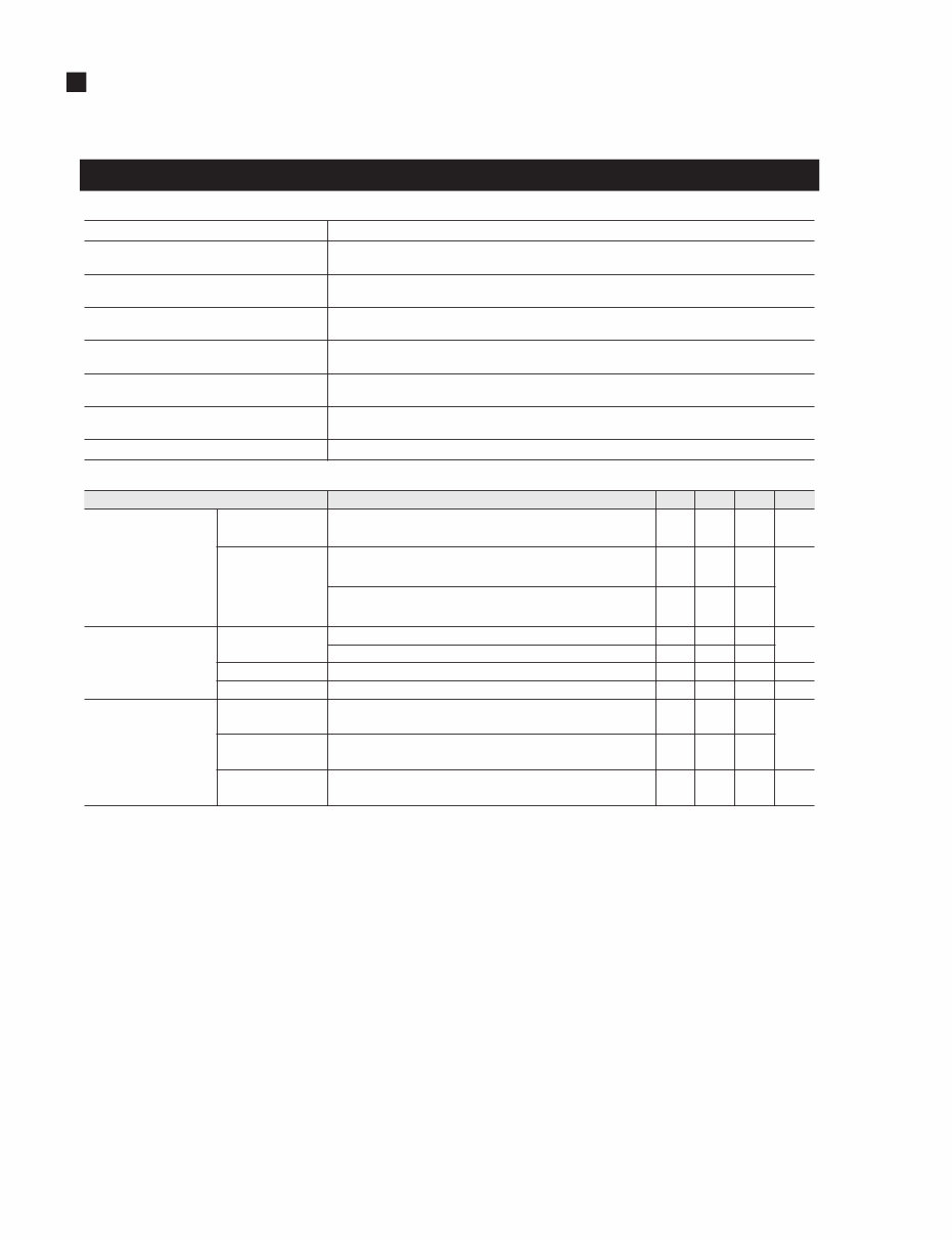
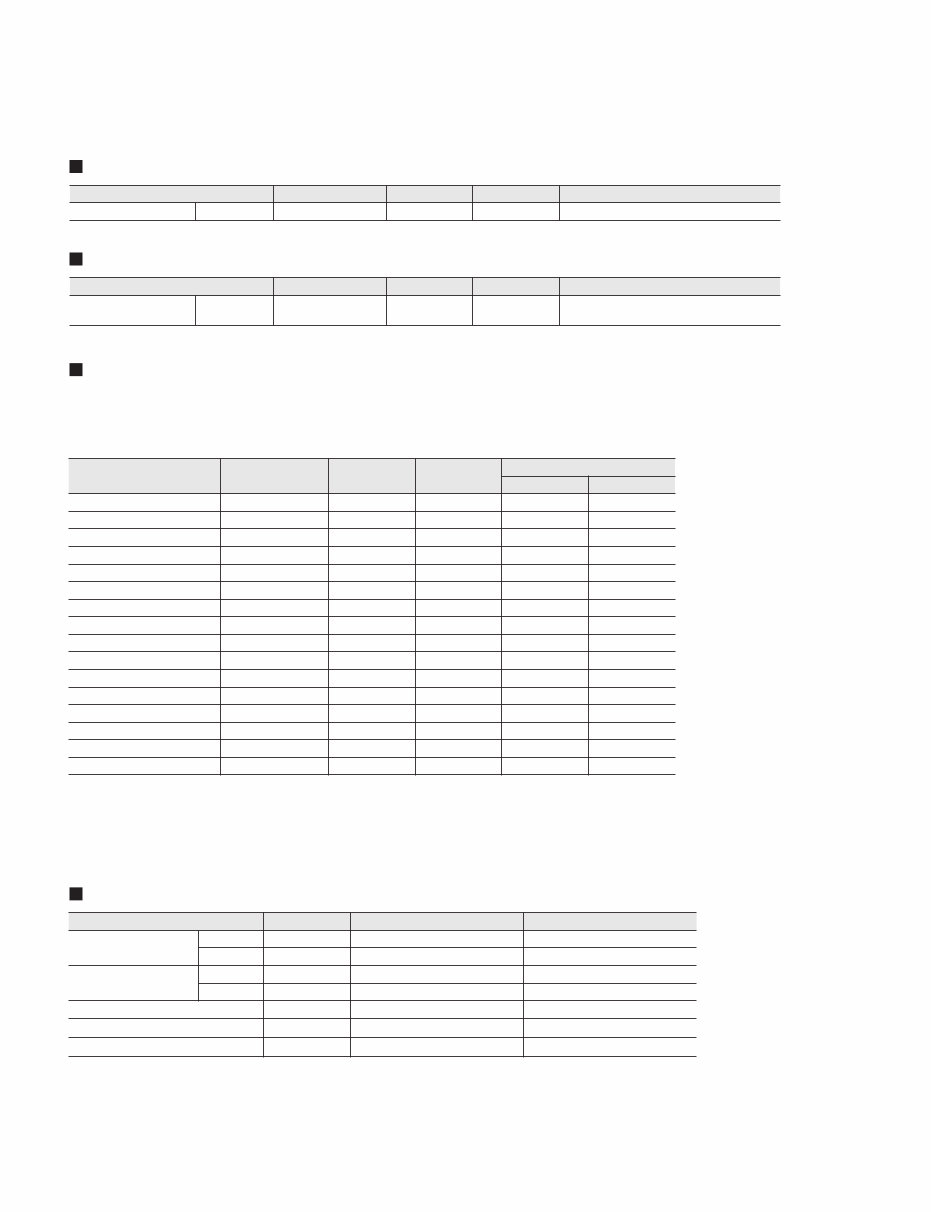
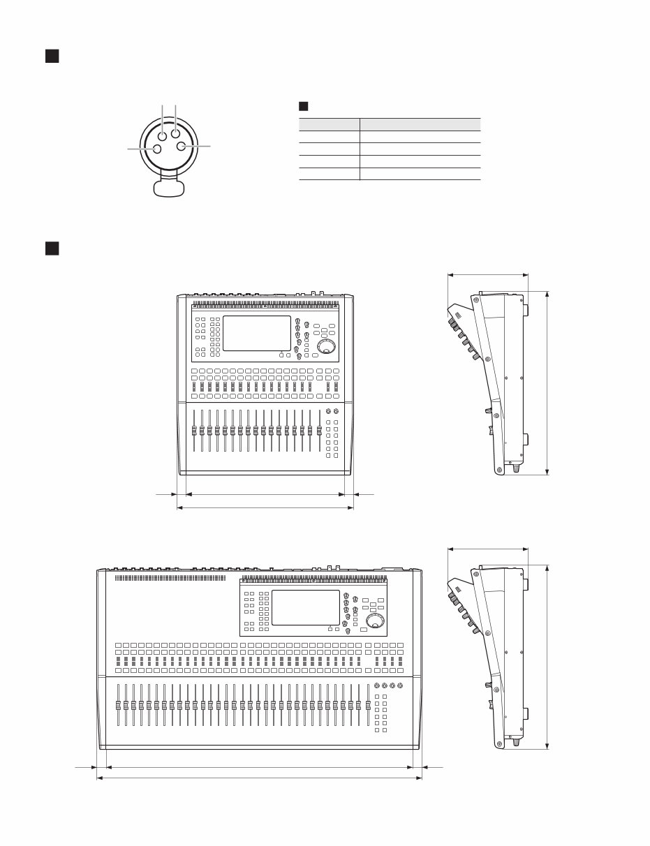
LS9-16/LS9-32 4 SPECIFICATIONS(総合仕様) General Specifications Signal Delay(シグナルディレイ) Less than 2.5 ms (INPUT to OMNI OUT @Fs=48 kHz) Dimensions(寸法) LS9-16: 480 x 220 x 500 mm LS9-32: 884 x 220 x 500 mm Net Weight(質量) LS9-16: 12.0 kg LS9-32: 19.4 kg Power Requirements(電源仕様) LS9-16: 95 W, 110—240 V, 50/60 Hz LS9-32: 170 W, 110—240 V, 50/60 Hz Temperature Range(温度範囲) Operating: +10˚C to +35˚C Storage: –20˚C to +60˚C Included Accessories(付属品) Owner’s Manual, AC Power Cord, Dust Cover (only LS9-32) Optional Accessories(別売オプション) mini-YGDAI cards, Gooseneck Light LA5000 (for LS9-32), Rack Mount Kit RK1 AC Power Cord Length(電源コード長) 250 cm Conditions Min. Typ. Max. Unit Sampling Frequency External Clock Frequency Range 39.69 50.88 kHz Jitter of PLL * * The jitter of input clock is less than 1ns. Digital Input Fs = 44.1 kHz or 48 kHz 10 ns Digital Input Fs = 39.69—50.88 kHz 20 Sampling Frequency Internal Clock Frequency Word Clock: INT 44.1 kHz 44.1 kHz Word Clock: INT 48 kHz 48 Accuracy Word Clock: INT 44.1 kHz or 48 kHz 50 ppm Jitter Word Clock: INT 44.1 kHz or 48 kHz 5 ns Fader Travel (Stroke) Resolution: 1,024 steps, +10 to –138, –∞ dB for all faders 100 mm Position Error ±1.5 Moving Time From end to the other end, Under normal software control 0.3 sec (WxHxD) (一般仕様) (取扱説明書、保証書、電源コード、ダストカバー(LS9-32のみ)) (mini-YGDAIカード、グースネックランプ LA5000 (LS9-32)、ラックマウントキット RK1) (サンプリング周波数 外部クロック) (周波数範囲) (PLLジッター *) ( 入力クロックのジッ ターは1ns以下) (サンプリング周波数 内部クロック) (周波数) (精度) (ジッター) (フェーダー) (ストローク) (位置誤差) (移動時間) *
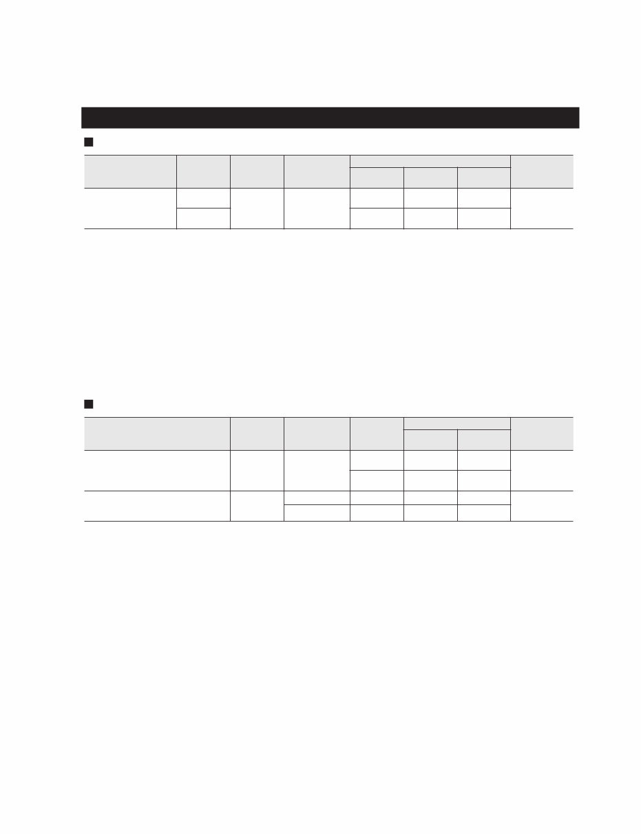
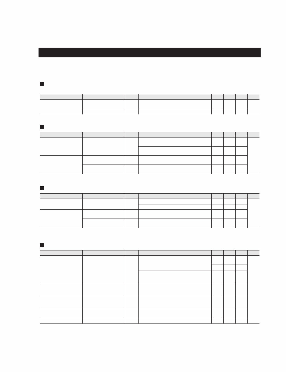
5 LS9-16/LS9-32 Analog Input Characteristics *1. Sensitivity is the lowest level that will produce an output of +4 dBu (1.23 V) or the nominal output level when the unit is set to maximum gain. (all fad- ers and level controls are maximum position.) *2. XLR-3-31 type connectors are balanced. (1=GND, 2=HOT, 3=COLD) * In these specifications, 0 dBu = 0.775 Vrms. * All input AD converters are 24-bit linear, 128-times oversampling. * +48V DC (phantom power) is supplied to INPUT XLR type connectors via each individual software controlled switch. Analog Output Characteristics *1. XLR-3-32 type connectors are balanced. (1=GND, 2=HOT, 3=COLD) *2. PHONES OUT stereo phone jack is unbalanced. (Tip=LEFT, Ring=RIGHT, Sleeve=GND) *3. There are switches inside the body to preset the maximum output level. *4. The position of the level control is 10 dB lowered from Max. * In these specifications, 0 dBu = 0.775 Vrms. * All output DA converters are 24-bit, 128-times oversampling. Input/output characteristics Input Terminals GAIN Actual Load Impedance For Use With Nominal Input Level Connector Sensitivity *1 Nominal Max. before clip INPUT 1-16 <LS9-16> INPUT 1-32 <LS9-32> –62 dB 3 kΩ 50-600 Ω Mics & 600 Ω Lines –82 dBu (61.6 μV) –62 dBu (0.616 mV) –42 dBu (6.16 mV) XLR-3-31 type (Balanced) *2 +10 dB –10 dBu (245 mV) +10 dBu (2.45 V) +30 dBu (24.5 V) Output Terminals Actual Source Impedance For Use With Nominal Gain Switch *3 Output Level Connector Nominal Max. before clip OMNI OUT 1-8 <LS9-16> OMNI OUT 1-16 <LS9-32> 75 Ω 600 Ω Lines +24 dB (default) +4 dBu (1.23 V) +24 dBu (12.3 V) XLR-3-32 type (Balanced) *1 +18 dB –2 dBu (616 mV) +18 dBu (6.16 V) PHONES OUT 15 Ω 8 Ω Phones — 75 mW *4 150 mW Stereo Phone Jack (TRS) (Unbalanced) *2 40 Ω Phones — 65 mW *4 150 mW (入出力特性) (アナログ入力特性) (アナログ出力特性) *1. 入力感度:すべてのフェーダーとレベルコントロールを最大位置にしたときに、+4 dBu(1.23 V)またはノミナル出力が得られる最小入力レベル *2. バランス型XLR-3-31端子(1=GND, 2=HOT, 3=COLD) * 0dBu = 0.775 Vrms. * すべてのAD コンバーターは、24 ビットリニア、128倍オーバーサンプリング * ソフトウェア制御でそれぞれのXLR タイプINPUT 端子にファンタム電源(+48 V DC)供給 *1. バランス型XLR-3-32端子(1=GND, 2=HOT, 3=COLD) *2. アンバランス型ステレオフォーン端子(Tip=LEFT, Ring=RIGHT, Sleeve=GND) *3. 内部スイッチにより、最大出力レベルを変更可能 *4. レベルコントロールの位置は、最大から10 dB下げた状態 * 0 dBu = 0.775 Vrms. * すべてのDA コンバーターは、24 ビット、128倍オーバーサンプリング
LS9-16/LS9-32 6 I/O Slot Characteristics The rear panel provides one slot (LS9-16) or two slots (LS9-32) in which separately sold mini-YGDAI cards can be installed. The following types of card can be used. Only Slot 1 has a serial interface (LS9-32). Refer to the Yamaha Pro Audio global website for the most recent information on mini-YGDAI cards. http://www. yamahaproaudio.com/ Control I/O Characteristics *1. Bus-powered hubs are not supported. *2. 4 pin=+12 V, 3 pin=GND, Supported lamp: max. 5 W Card Name Function Input Output The number of available cards LS9-16 LS9-32 MY8-AD24 Analog In 8In — 1 2 MY8-AD96 Analog In 8In — 1 2 MY8-ADDA96 Analog In/Out 8In 8Out 1 2 MY8-AE AES/EBU 8In 8Out 1 2 MY8-AE96 AES/EBU 8In 8Out 1 2 MY8-AE96S AES/EBU 8In 8Out 1 2 MY8-AEB AES/EBU 8In 8Out 1 2 MY8-AT ADAT 8In 8Out 1 2 MY8-DA96 Analog Out — 8Out 1 2 MY8-TD TASCAM 8In 8Out 1 2 MY4-DA Analog Out — 4Out 1 2 MY4-AD Analog In 4In — 1 2 MY16-AE AES/EBU 16In 16Out 1 2 MY16-AT ADAT 16In 16Out 1 2 MY16-TD TASCAM 16In 16Out 1 2 MY16-CII CobraNet 16In 16Out 1 2 Terminal Format Level Connector MIDI IN MIDI — DIN Connector 5P OUT MIDI — DIN Connector 5P WORD CLOCK IN — TTL/75 Ω terminated BNC Connector OUT — TTL/75 Ω BNC Connector NETWORK (Ethernet) 100Base-T 100Base-T RJ-45 USB USB 1.1 Host USB *1 USB A Connector (Female) LAMP (LS9-32 only) — 0V–12V XLR-4-31 type *2 Digital Input Characteristics Digital Output Characteristics Terminal Format Data Length Level Connector 2TR IN DIGITAL Coaxial IEC-60958 24 bit 0.5 Vpp/75 Ω RCA Pin Jack Terminal Format Data Length Level Connector 2TR OUT DIGITAL Coaxial IEC-60958 Consumer Use 24 bit 0.5 Vpp/75 Ω RCA Pin Jack (デジタル入力特性) (デジタル出力特性) (スロット仕様) (コントロール入出力仕様) 別売のmini-YGDAI カードを装着するためのスロットが、LS9-16 には1 基、LS9-32には 2基あります。 以下のカードがご使用になれます。 LS9-32のシリアルインターフェースはスロット 1のみ装備しています。 mini-YGDAIカードの最新情報については、ヤマハプロオーディオのウェブサイトをご覧ください。 *1. バスパワーで動作するハブは動作保証外 *2. 4pin=+12V、3pin=GND、ランプ定格は5Wまで対応
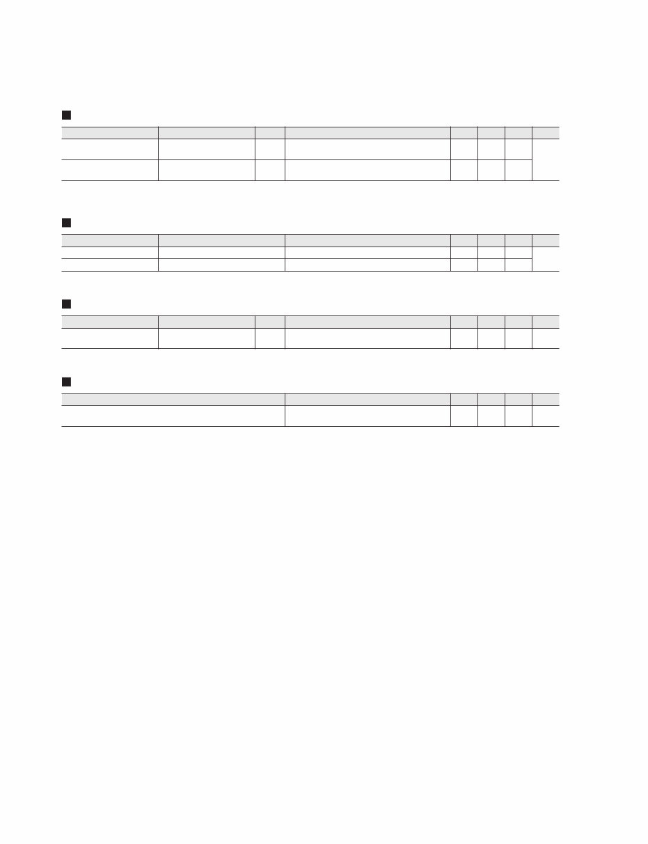
7 LS9-16/LS9-32 All faders are nominal when measured. Output impedance of signal generator: 150 ohms Frequency Response Fs = 44.1 kHz or 48 kHz@20 Hz–20 kHz, referenced to the nominal output level @1 kHz Gain Error Fs = 44.1 kHz or 48 kHz@1 kHz Total Harmonic Distortion Fs = 44.1 kHz or 48 kHz * Total Harmonic Distortion is measured with a 18 dB/octave filter @80 kHz Hum & Noise Fs = 44.1 kHz or 48 kHz, EIN = Equivalent Input Noise * Hum & Noise are measured with a 6 dB/octave filter @12.7 kHz; equivalent to a 20 kHz filter with infinite dB/octave attenuation. Electrical characteristics Input Output RL Conditions Min. Typ. Max. Unit INPUT 1-16 <LS9-16> INPUT 1-32 <LS9-32> OMNI OUT 1-8 <LS9-16> OMNI OUT 1-16 <LS9-32> 600 Ω GAIN: max. –1.5 0.0 0.5 dB PHONES OUT 8 Ω GAIN: max. –3.0 0.0 0.5 Input Output RL Conditions Min. Typ. Max. Unit INPUT 1-16 <LS9-16> INPUT 1-32 <LS9-32> OMNI OUT 1-8 <LS9-16> OMNI OUT 1-16 <LS9-32> 600 Ω Input level: –62 dBu, GAIN: max. → Output level: +4.0 dBu (Typ.) –2.0 2.0 dB Input level: +10 dBu, GAIN: min. → Output level: +4.0 dBu (Typ.) –2.0 2.0 Internal Oscillator OMNI OUT 1-8 <LS9-16> OMNI OUT 1-16 <LS9-32> 600 Ω Full scale output, Output level: +24.0 dBu –0.5 0.5 0.5 PHONES OUT 8 Ω –30 dBFs, Phones level control: max. → Output level: 0 dBu (Typ.) –0.5 Input Output RL Conditions Min. Typ. Max. Unit INPUT 1-16 <LS9-16> INPUT 1-32 <LS9-32> OMNI OUT 1-8 <LS9-16> OMNI OUT 1-16 <LS9-32> 600 Ω +4 dBu@20 Hz–20 kHz, GAIN: max. 0.1 % +4 dBu@20 Hz–20 kHz, GAIN: min. 0.05 Internal Oscillator OMNI OUT 1-8 <LS9-16> OMNI OUT 1-16 <LS9-32> 600 Ω Full scale output @1 kHz 0.02 PHONES OUT 8 Ω Full scale output @1 kHz, Phones level control: max. 0.2 Input Output RL Conditions Min. Typ. Max. Unit INPUT 1-16 <LS9-16> INPUT 1-32 <LS9-32> OMNI OUT 1-8 <LS9-16> OMNI OUT 1-16 <LS9-32> 600 Ω Rs=150 Ω, GAIN: max. Master fader: nominal, One channel fader: nom- inal –128 EIN dBu –62 Rs=150 Ω, GAIN: min. Master fader: nominal, One channel fader: nom- inal –84 –79 All Inputs <LS9-16> OMNI OUT 1-8 <LS9-16> 600 Ω Rs=150 Ω, GAINs: min. Master fader: nominal, All channel faders: nomi- nal –67 All Inputs <LS9-32> OMNI OUT 1-16 <LS9-32> 600 Ω Rs=150, GAINs: min. Master fader: nominal, All channel faders: nomi- nal –64 — OMNI OUT 1-8 <LS9-16> OMNI OUT 1-16 <LS9-32> 600 Ω Residual output noise, Stereo Master: off –86 — PHONES OUT 8 Ω Residual output noise, Phones level control: min. –86 0.0 0.0 0.0 0.0 (電気特性) 測定時のフェーダーはすべてノミナルレベル、 シグナルジェネレーターの出力インピーダンスは150 Ω (周波数特性) (ゲインエラー) (全高調波歪率) (ハム& ノイズ)
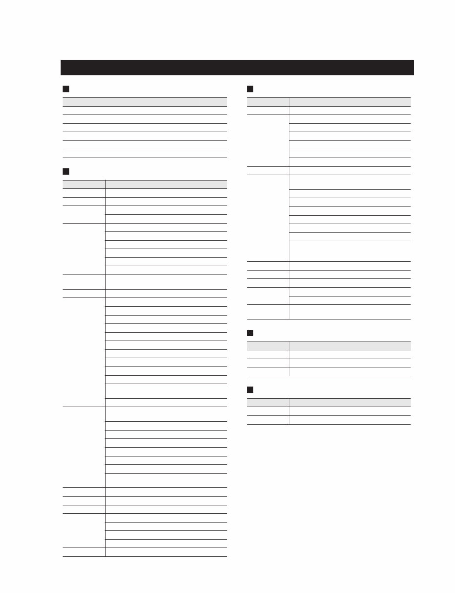
LS9-16/LS9-32 Crosstalk@1 kHz Maximum Voltage Gain@1 kHz Phantom Voltage From To Conditions Min. Typ. Max. Unit INPUT n INPUT (n–1) or (n+1) CH 1-16 {1-32}, Adjacent inputs, GAIN: min. –80 dB OMNI OUT n OMNI OUT (n–1) or (n+1) OMNI OUT 1-8 {1-16}, Input to output –80 Input Output RL Conditions Min. Typ. Max. Unit INPUT 1-16 <LS9-16> INPUT 1-32 <LS9-32> OMNI OUT 1-8 <LS9-16> OMNI OUT 1-16 <LS9-32> 600 Ω Rs=150 Ω, Input GAIN: max. 86 dB Output Conditions Min. Typ. Max. Unit INPUT 1-16 <LS9-16> INPUT 1-32 <LS9-32> hot & cold: No load 46 48 50 V Dynamic Range Fs = 44.1 kHz or 48 kHz * Dynamic range is measured with a 6 dB/octave filter @12.7 kHz; equivalent to a 20 kHz filter with infinite dB/octave attenuation. Input Output RL Conditions Min. Typ. Max. Unit INPUT 1-16 <LS9-16> INPUT 1-32 <LS9-32> OMNI OUT 1-8 <LS9-16> OMNI OUT 1-16 <LS9-32> 600 Ω AD + DA, GAIN: min. 108 dB — OMNI OUT 1-8 <LS9-16> OMNI OUT 1-16 <LS9-32> 600 Ω DA Converter 110 (クロストーク @1 kHz) (最大電圧ゲイン @1 kHz) (ファンタム電源) (ダイナミックレンジ)
9 LS9-16/LS9-32 Libraries Input Function Output Function Output Port Processor Other Functions Name Number Total Scene Memory Preset 1 + User 300 301 Input EQ Library Preset 40 + User 159 199 Output EQ Library Preset 3 + User 196 199 Dynamics Library Preset 41 + User 158 199 Effect Library Preset 57 + User 142 199 GEQ Library Preset 1 + User 199 200 Function Parameter Phase Normal/Reverse Attenuator –96 to +24 dB HPF Slope= 12 dB/Oct Frequency= 20 Hz to 600 Hz 4 Band Equal- izer Frequency= 20 Hz to 20 kHz Gain= –18 dB to +18 dB Q= 0.10 to 10.0 Low Shelving (Low Band) High Shelving, LPF (High Band) Type I/Type II Insert (only ch1-32) Insert Point: Pre EQ/Pre Fader Direct Out Direct Out Point: Pre HPF/Pre EQ Dynamics 1 Type: Gate/Ducking/Comp/Expander Threshold= –54 dB to 0 dB Ratio= 1:1 to ∞:1 Attack= 0 msec to 120 msec Hold= 0.02 msec to 1.96 sec Decay= 5 msec to 42.3 sec (Release) Releace= 5msec to 42.3 sec Range= –70 dB to 0 dB Gain= –18 dB to 0 dB, 0 dB to +18 dB Knee= Hard to 5 (soft) Key In: Self Pre EQ/Self Post EQ/Mix Out13-16 Ch1-STIN4R (8ch block) Key In Filter: HPF/LPF/BPF Dynamics2 Type: Comp/De-Esser/Compander H/Com- pander S Threshold= –54 dB to 0 dB Ratio= 1:1 to ∞:1 Attack= 0 msec to 120 msec Release= 5 msec to 42.3 sec Gain= –18 dB to 0 dB, 0 dB to +18 dB Knee= Hard to 5 (soft) Key In: Self Pre EQ/Self Post EQ/Mix Out13-16 Ch1-STIN4R (8ch block) Fader Level: 1024 steps,∞, –138 dB to +10 dB On On/Off Mute Group 8 Groups Mix Send 16 sends Fix/Variable can be set each two mixes Mix Send Point: Pre EQ/Pre Fader/Post On Level: 1024 steps,∞, –138 dB to +10 dB LCR Pan CSR= 0% to 100% Function Parameter Attenuator –96 to +24 dB 4Band Equalizer Frequency= 20 Hz to 20 kHz Gain= –18 dB to +18 dB Q= 0.10 to 10.0 Low Shelving (Low Band) High Shelving, LPF (High Band) Type I/Type II Insert Insert Point: Pre EQ/Post EQ/Pre Fader/Post On Dynamics 1 Type: Comp/Expander/Compander H/Com- pander S Threshold= –54 dB to 0 dB Ratio= 1:1 to ∞:1 Attack= 0 msec to 120 msec Release= 5 msec to 42.3 sec Gain= –18 dB to 0 dB, 0 dB to + 18 dB Knee= Hard to 5 (soft) Key In: Self Pre EQ/Self Post EQ/Mix Out13-16 MIX1-16/MTRX1-8/STIN LR/MONO(C) (8ch block) Fader Level: 1024 steps,∞, –138 dB to +10 dB On On/Off Mute Group 8 Groups Mix to Matrix Stereo to Matrix Matrix Send Point: Pre Fader/Post On Level: 1024 steps,∞, –138 dB to +10 dB Oscillator Level= 0 to –96 dB (1 dB step) On/Off= Software control Function Parameter Out Port Delay 0 msec to 600 msec Out Port Phase Normal/Reverse Attenuator –96 to +24 dB Function Parameter GEQ 31 bands x 4(8) systems Effects Stereo In/Stereo Out multi effector x 4 systems (その他機能) (ライブラリー) (入力チャンネル) (出力チャンネル) (出力ポート) (プロセッサー)
Master the maintenance and repair of your Yamaha LS9 Digital Mixing Console with this detailed Service Manual. Perfect for sound engineers, technicians, and audio enthusiasts, this manual provides in-depth information for the upkeep, troubleshooting, and repair of your sophisticated LS9 console. Inside, you'll find comprehensive step-by-step instructions, clear illustrations, and extensive exploded-view diagrams.
Renowned for its exceptional sound quality and versatile functionality, the Yamaha LS9 requires knowledgeable care and occasional technical adjustments. This manual is your essential guide, offering insights into every feature and component of your LS9 console.
Whether you're calibrating audio levels, diagnosing electronic issues, or conducting routine checks, this manual covers a broad spectrum of maintenance and repair topics. It's designed to guide you through complex procedures with clear and precise instructions, supplemented with detailed images and diagrams for clarity.
Enjoy the convenience of a digital format that makes accessing and navigating this manual effortless. Suitable for viewing on multiple devices, including PCs, tablets, and smartphones, you can quickly find and reference the information you need. This format eliminates the bulk and limitations of traditional paper manuals, allowing for efficient, on-the-go consultation.
Printable: Yes
Language: English
Compatibility: Compatible across a wide range of devices including PCs, Macs, smartphones, and tablets.
Requirements: A PDF reader like Adobe Reader (free)