Yamaha DTXPRESS II (2) Drum Trigger Module Service Manual & Repair Guide
What's Included?
Lifetime Access
Fast Download Speeds
Online & Offline Access
Access PDF Contents & Bookmarks
Full Search Facility
Print one or all pages of your manual
1.373K-456 I M Printed in Japan '02.07 SERVICE MANUAL ED 011647 This document is using chlorine free (ECF) paper. このサービスマニュアルはエコパルプ� (ECF: 無塩素系漂白パルプ)を使用しています。� 20020720-48000 ■ CONTENTS(目次) SPECIFICATION(総合仕様) ........................................................ 3/4 PANEL LAYOUT(パネルレイアウト) ............................................. 5 UNIT LAYOUT(ユニットレイアウト) ............................................. 6 BLOCK DIAGRAM(ブロックダイアグラム) .................................. 7 DISASSEMBLY PROCEDURE(分解手順) ................................... 8 LSI PIN DESCRIPTION(LSI 端子機能表) ................................... 11 IC BLOCK DIAGRAM(IC ブロック図) ......................................... 12 CIRCUIT BOARDS(シート基板図) .............................................. 14 TEST PROGRAM(テストプログラム) ................................... 21/30 ERROR MESSAGES(エラーメッセージ) ............................. 39/40 MIDI IMPLEMENTATION CHART (MIDI インプリメンテーションチャート) ...................... 41 PARTS LIST OVERALL CIRCUIT DIAGRAM(総回路図) DRUM TRIGGER MODULE DTXP2
DTXP2 2 IMPORTANT NOTICE This manual has been provided for the use of authorized Yamaha Retailers and their service personnel. It has been assumed that basic service procedures inherent to the industry, and more specifically Yamaha Products, are already known and understood by the users, and have therefore not been restated. WARNING: Failure to follow appropriate service and safety procedures when servicing this product may result in personal injury, destruction of expensive components, and failure of the product to perform as specified. For these reasons, we advise all Yamaha product owners that all service required should be performed by an authorized Yamaha Retailer or the appointed service representative. IMPORTANT: The presentation or sale of this manual to any individual or firm does not constitute authorization, certification or recognition of any applicable technical capabilities, or establish a principle-agent relationship of any form. The data provided is believed to be accurate and applicable to the unit(s) indicated on the cover. The research, engineering, and service departments of Yamaha are continually striving to improve Yamaha products. Modifications are, therefore, inevitable and changes in specification are subject to change without notice or obligation to retrofit. Should any discrepancy appear to exist, please contact the distributor's Service Division. WARNING: Static discharges can destroy expensive components. Discharge any static electricity your body may have accumulated by grounding yourself to the ground bus in the unit (heavy gauge black wires connect to this bus). IMPORTANT: Turn the unit OFF during disassembly and part replacement. Recheck all work before you apply power to the unit. WARNING: CHEMICAL CONTENT NOTICE! The solder used in the production of this product contains LEAD. In addition, other electrical/electronic and /or plastic (where applicable) components may also contain traces of chemicals found by the California Health and Welfare Agency (and possibly other entities) to cause cancer and/or birth defects or other reproductive harm. DO NOT PLACE SOLDER, ELECTRICAL/ELECTRONIC OR PLASTIC COMPONENTS IN YOUR MOUTH FOR ANY REASON WHAT- SOEVER! Avoid prolonged, unprotected contact between solder and your skin! When soldering, do not inhale solder fumes or expose eyes to solder/flux vapor! If you come in contact with solder or components located inside the enclosure of this product, wash your hands before handling food. LITHIUM BATTERY HANDLING This product uses a lithium battery for memory back-up. WARNING: Lithium batteries are dangerous because they can be exploded by improper handling. Observe the following precautions when handling or replacing lithium batteries. • Leave lithium battery replacement to qualified service personnel. • Always replace with batteries of the same type. • When installing on the PC board by soldering, solder using the connection terminals provided on the battery cells. Never solder directly to the cells. Perform the soldering as quickly as possible. • Never reverse the battery polarities when installing. • Do not short the batteries. • Do not attempt to recharge these batteries. • Do not disassemble the batteries. • Never heat batteries or throw them into fire. ADVARSEL! Lithiumbatteri-Eksplosionsfare ved fejlagtig håndtering. Udskiftning må kun ske med batteri af samme fabrikat og type. Levér det brugte batteri tilbage til leverandøren. VARNING Explosionsfara vid felaktigt batteribyte. Använd samma batterityp eller en ekvivalent typ som rekommenderas av apparattillverkaren. Kassera använt batteri enligt fabrikantens instruktion. VAROITUS Paristo voi räjähtää, jos se on virheellisesti asennettu. Vaihda paristo ainoastaan laitevalmistajan suosittelemaan tyyppiin. Hävitä käytetty paristo valmistajan ohjeiden mukaisesti. The following information complies with Dutch Official Gazette 1995. 45; ESSENTIALS OF ORDER ON THE COLLECTION OF BATTERIES. • Please refer to the diassembly procedure for the removal of Back-up Battery. • Leest u voor het verwijderen van de backup batterij deze beschrijving.
3 DTXP2 ■ SPECIFICATIONS Tone Generator 16 bit AWM2 Maximum polyphony 32 Voices 928 drum, percussion voices and effects 128 keyboard voices (GM system level 1) Drum kits 48 Preset 32 User memory locations Trigger setups 5 Preset 4 User memory locations Sequencer tracks 2 (TR1, TR2) Song control Main song Start/Stop, note chase Pad song 3 songs can be played at the same time, Trigger Control Other Sequencer Functions MIDI sync play, Quantize (while recording, in Song Edit job mode), Mute (rhythm mute, drum instrument mute), Groove Check Song 95 Preset 32 User memory locations Record modes Real-time Controls LED buttons 6 (DRUMKIT, SONG, TRIG, VOICE, UTIL, CLICK) Buttons 9 ( W /■, SAVE/ENTER, SHIFT, PAGE H / G , SELECT Q / W , VALUE–/+) Knobs MASTER VOLUME/POWER SW (push), ACCOMP. VOLUME, AUX VOLUME, CLICK VOLUME Display 16 x 2 LCD display (w/Back light) Connections Front Panel Aux input (stereo mini jack) Head phone (stereo phone jack) Rear Panel MIDI input/output Foot controller (stereo phone jack) HOST SELECT SW TO HOST (mini DIN jack) Output L/MONO (mono phone jack) Output R (mono phone jack) Trigger Inputs 1 – 8 (stereo phone jack➔L : trigger input, R : rim switch) Trigger Input 9/10 (stereo phone jack➔L, R : trigger input) Trigger attenuation switch 1-6 (DIP SW) Power supply DC 12V/AC adaptor (PA-3B or PA-3C) Power Requirement 4.8 Watt Dimensions (W x H x D) 220 x 240 x 44 mm (8-11/16” x 9-3/16” x 1-5/16”) Weight 1.6 kg (3 lbs 8 oz) Accessories Owner’s Manual AC adaptor * Specifications and descriptions in this service manual are for information purpose only. Yamaha Corp. reserves the right to change or modify products or specifications at any time without prior notice.
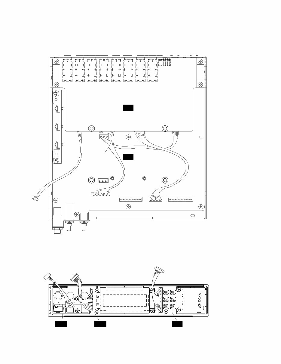
DTXP2 8 ■ DISASSEMBLY PROCEDURE(分解手順) 1 トップカバー 1-1 [50] ネジ5 を して、トップカバーを しま す。(Fig. 1) 2 フロントパネルユニット 2-1 トップカバーを します。(1 ) 2-2 [10c] ネジ4 を して、フロントパネルユニ ットを します。(Fig. 3) 3 JKシートAss'y 3-1 トップカバーを します。(1 ) 3-2 [C60] ネジ4 を して、JKシートAss'yを し ます。 (Fig. 2) ※ [C ]シールドタンシAss'yを くさ い に 意 して さい。 1 Top Cover 1-1 Remove the five (5) screws marked [50]. The top cover can then be removed. (Fig. 1) 2 Front Panel Unit 2-1 Remove the top cover. (See Procedure 1.) 2-2 Remove the four (4) screws marked [10c]. The front panel unit can then be removed. (Fig. 3) 3 JK Circuit Board Assembly 3-1 Remove the top cover. (See Procedure 1.) 3-2 Remove the four (4) screws marked [C60]. The JK circuit board assembly can then be removed. (Fig. 2) * Take care not to lose [C70] shield terminal. [50] Top cover (トップカバー) (Fig. 1) [50]: Bind Head Tapping Screw-B 3.0X6 MFZN2BL (EP600230)+バインドBタイト� [50] [50] [50] [50] (Fig. 2) [C60]: Bind Head Tapping Screw-B 3.0X6 MFZN2BL (EP600230)+バインドBタイト� [C70]: Shield Terminal Assembly (V3814600)シールドタンシAss'y (Fig. 3) [10c]: Bind Head Tapping Screw-B 3.0X6 MFZN2BL (EP600230)+バインドBタイト� [10c] [10c] [C60] [C70] [C60] JK Front panel (フロントパネル) [C70]
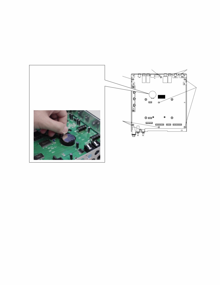
9 DTXP2 4 DMシートAss'y 4-1 トップカバーを します。(1 ) 4-2 フロントパネルユニットを します。(2 ) 4-3 JKシートAss'yを します。(3 ) 4-4 [C30] ネジ8 を し、[C40] ネジ2 を して、 DMシートAss'yを します。(Fig. 4) 5 LCDシートAss'y 5-1 トップカバーを します。(1 ) 5-2 フロントパネルユニットを します。(2 ) 5-3 [40] ネジ4 を して、LCDシートAss'yを し ます。(Fig. 5) 6 AUXシートAss'y 6-1 トップカバーを します。(1 ) 6-2 フロントパネルユニットを します。(2 ) 6-3 [60] ネジ2 を して、AUXステー き AUX シートAss'yを り します。[A] ツマミ2 を し、[B] 角ネジ2 、[50c] ネジ1 を して、AUXシートを します。(Fig. 5) 7 PNシートAss'y 7-1 トップカバーを します。(1 ) 7-2 フロントパネルユニットを します。(2 ) 7-3 [A90] ネジ2 を して、パネルステーを し、 [B90] ネジ3 を して、PNシートAss'yを し ます。(Fig. 5) 4 DM Circuit Board Assembly 4-1 Remove the top cover. (See Procedure 1.) 4-2 Remove the front panel unit. (See Procedure 2.) 4-3 Remove the JK circuit board assembly. (See Procedure 3.) 4-4 Remove the eight (8) screws marked [C30] and the two (2) screws marked [C40]. The DM circuit board assembly can then be removed. (Fig. 4) 5 LCD Circuit Board Assembly 5-1 Remove the top cover. (See Procedure 1.) 5-2 Remove the front panel unit. (See Procedure 2.) 5-3 Remove the four (4) screws marked [40]. The LCD circuit board assembly can then be removed. (Fig. 5) 6 AUX Circuit Board Assembly 6-1 Remove the top cover. (See Procedure 1) 6-2 Remove the front panel unit. (See Procedure 2.) 6-3 Remove the two (2) screws marked [60]. The AUX circuit board assembly with AUX stay can then be removed. Remove the two (2) knobs marked [A], the two (2) hexagonal nuts marked [B] and the screw marked [50c]. The AUX circuit board can then be removed. (Fig. 5) 7 PN Circuit Board Assembly 7-1 Remove the top cover. (See Procedure 1) 7-2 Remove the front panel unit. (See Procedure 2.) 7-3 Remove the two (2) screws marked [A90], the panel stay and the three (3) screws marked [B90]. The PN circuit board assembly can then be removed. (Fig. 5) (Fig. 4) [C30]: Bind Head Tapping Screw-B 3.0X6 MFZN2BL (EP600230)+バインドBタイト� [C40]: Bind Head Tapping Screw-B 3.0X8 MFZN2BL (EP600190)+バインドBタイト� [C40] [C30] [C30] [C30] DM [C30] • How to remove a lithium battery リチ ム し Remove the hook while pressing the spring. The lithium battery can be removed. バネを してフックを す リチ ム が れます。 The lithium battery should surely use VS246400 (CR2450). リチ ム ずVS (CR を し て さい。
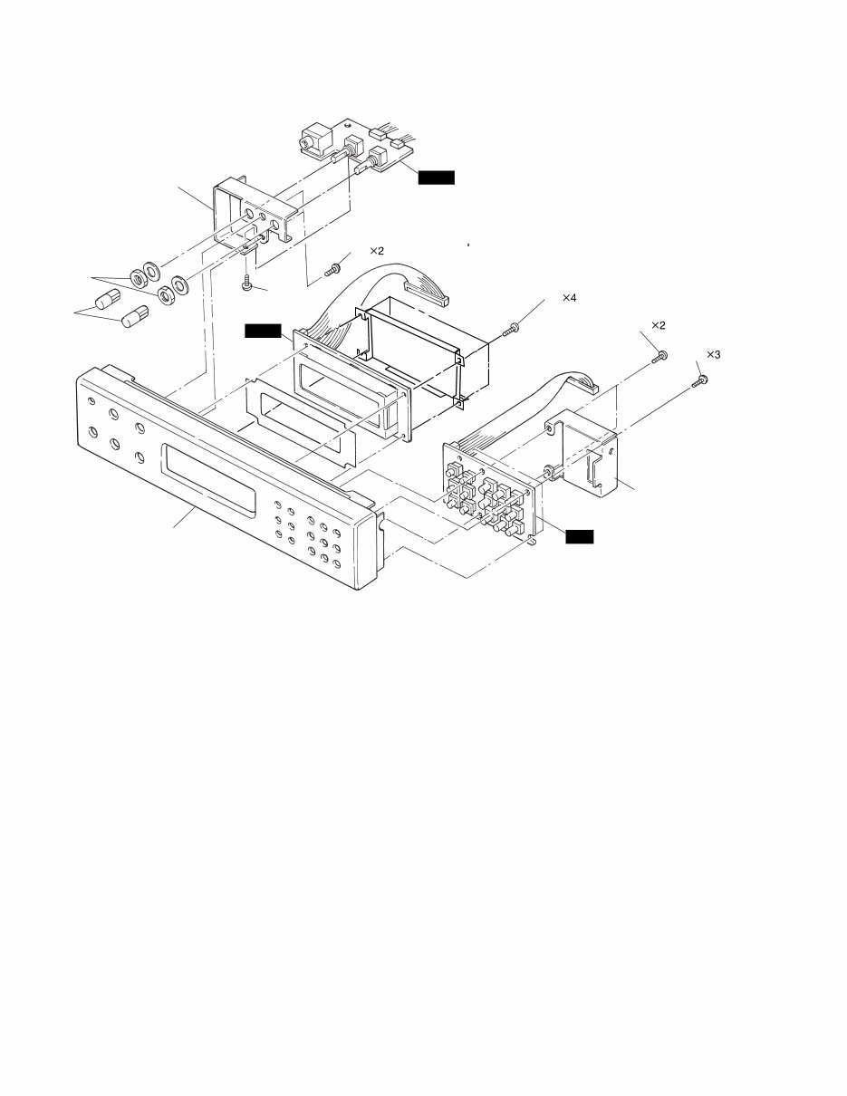
DTXP2 10 Front panel(フロントパネル) (Fig. 5) [40]: Bind Head Tapping Screw-P 2.6X8 MFZN2Y (EP620100)+バインドPタイト [50c]: Bind Head Tapping Screw-B 3.0X6 MFZN2BL (EP600230)+バインドBタイト [60]: Bind Head Tapping Screw-B 2.6X8 MFZN2Y (EP620100)+バインドPタイト [90]: Bind Head Tapping Screw-P 2.6X8 MFZN2BL (EP620100)+バインドPタイト� [40] [60] [50c] [B90] [A90] Panel stay (パネルステー) PN LCD AUX Stay(AUXステー) [A] [B]
Are you experiencing issues with your Yamaha DTXPRESS II Drum Trigger Module? Instead of spending a significant amount on repairs or replacements, why not take matters into your own hands?
This comprehensive service and repair manual is utilized by the Official Certified Yamaha Technicians and is designed to assist you in troubleshooting and fixing your Drum Trigger Module.
The manual includes detailed content such as specifications, panel layout, unit layout, block diagram, disassembly procedure, LSI pin description, IC block diagram, circuit boards, test program, error messages, MIDI implementation chart, parts list, and overall circuit diagram.
It is packed with high-resolution images and step-by-step instructions, ensuring that you can effectively service and repair the device with ease.
Upon purchase, you will gain instant access to the manual without any shipping fees or delays, allowing you to commence your repairs promptly.
Specifications:
Language: English
Format: PDF
Pages: 52
Platform: Windows and MAC
If you are in search of a specific service manual, feel free to reach out to us with your request. With one of the most extensive service manual databases available, there's a good chance that we can assist you.
Recently Viewed
5,521,897Happy Clients
2,594,462eManuals
1,120,453Trusted Sellers
15Years in Business
Price:
Actual Price:
Yamaha DTXPRESS II (2) Drum Trigger Module Service Manual & Repair Guide

 Drum Trigger Module Service Manual & Repair Guide")