Conventions used in this guide TIP: Tips provide helpful hints or shortcuts. NOTE: Notes provide important information to explain a concept or to complete a task. CAUTION: Cautions indicate procedures that you should follow to avoid losing data or damaging the product. WARNING! Warnings alert you to specific procedures that you should follow to avoid personal injury, catastrophic loss of data, or extensive damage to the product. ENWW iii
iv Conventions used in this guide ENWW
Table of contents 1 Removal and replacement ................................................................................................ 1 Introduction ............................................................................................................................. 2 Removal and replacement strategy ............................................................................................. 2 General cautions during removal and replacement ........................................................ 2 Electrostatic discharge ............................................................................................... 3 Required tools ........................................................................................................... 3 Types of screws ........................................................................................................ 4 Service approach ..................................................................................................................... 5 Before performing service .......................................................................................... 6 After performing service ............................................................................................. 6 Post-service test ......................................................................................................... 7 Print-quality test .......................................................................................... 7 Copy-quality test ........................................................................................ 7 DC controller PCA ..................................................................................................... 8 Parts removal order ................................................................................................... 9 Removal and replacement procedures ...................................................................................... 11 Customer self repair (CSR) components ...................................................................... 11 Toner cartridges ....................................................................................... 11 Staple cartridge ....................................................................................... 13 Duplex-reverse guide ................................................................................ 14 Toner-collection unit .................................................................................. 15 Formatter PCA ......................................................................................... 17 Fax PCA and cable .................................................................................. 18 Remove the fax PCA and cable ................................................... 18 Hard drive .............................................................................................. 20 Remove the HDD ....................................................................... 20 Install a replacement hard drive .................................................. 22 Tray 2 and 3 ........................................................................................... 23 Fuser ...................................................................................................... 24 Pickup roller and separation pad (Tray 1) ................................................... 25 Pickup roller (Tray 2) ................................................................................ 27 Pickup and feed rollers (Tray 3) .................................................................. 29 ENWW v
Separation roller (Tray 2) .......................................................................... 31 Secondary transfer roller ........................................................................... 32 Reinstall the transfer roller ........................................................... 33 Intermediate transfer belt (ITB) .................................................................... 34 Front-door assembly ................................................................................. 37 Foam reflector kit ..................................................................................... 38 Document feeder pickup roller ................................................................... 39 Document feeder separation pad and spring ............................................... 41 Control panel .......................................................................................... 44 Control-panel assembly (M575c model) ...................................................... 47 Important removal considerations ................................................ 47 Remove the control-panel assembly .............................................. 49 Reinstall the control-panel assembly ............................................. 56 Control-panel assembly to keyboard FFC (M575c model) .............................. 63 Important considerations ............................................................ 63 Remove the control-panel assembly to keyboard FFC ..................... 64 Reinstall the control-panel assembly to keyboard FFC ..................... 65 Keyboard assembly (M575c model) ........................................................... 68 Remove the keyboard assembly .................................................. 68 Keyboard overlay (M575c model) .............................................................. 72 Install a keyboard overlay .......................................................... 72 Back-side background selector assembly (M575c model) .............................. 76 Right door (optional paper feeder) ............................................................. 78 External panels, covers, and doors ............................................................................ 80 Identification and location ......................................................................... 80 Control-panel USB cover ........................................................................... 81 Control-panel HIP (hardward integration pocket) .......................................... 82 Front-upper cover ..................................................................................... 83 Remove the front-upper cover ...................................................... 83 Stapler cover ........................................................................................... 85 Remove the stapler cover ............................................................ 85 Right-door assembly ................................................................................. 86 Right-rear cover ........................................................................................ 90 Left cover ................................................................................................ 92 Rear-upper cover ...................................................................................... 95 Left-upper cover ........................................................................................ 97 Remove the left-upper cover ........................................................ 97 Rear cover ............................................................................................... 98 Remove the rear cover ............................................................... 98 Right-front cover ..................................................................................... 100 Remove the right-front cover ...................................................... 100 vi ENWW
Delivery cover ........................................................................................ 104 Remove the delivery cover ........................................................ 104 Right-top cover ....................................................................................... 106 Remove the right-top cover ....................................................... 106 Upper-right cover ................................................................................... 108 Remove the upper-right cover .................................................... 108 Front-top cover ....................................................................................... 110 Remove the front-top cover ....................................................... 110 Rear-top cover ....................................................................................... 112 Remove the rear-top cover ........................................................ 112 Document feeder and scanner assemblies ................................................................ 114 Cover front (document feeder front cover) .................................................. 114 Cover rear (document feeder rear cover) ................................................... 116 Deskew mylar and separation mylar ......................................................... 118 Document feeder tray extender ................................................................ 120 Document feeder jam-access cover ........................................................... 121 Docuement feeder roller cover ................................................................. 124 Document feeder whole unit .................................................................... 127 Reinstall the document feeder .................................................... 129 Document feeder whole unit (M575c model) ............................................. 130 Remove the document feeder .................................................... 130 Reinstall the document feeder .................................................... 131 Document feeder hinge assy .................................................................... 132 Scanner-control board (SCB) .................................................................... 133 Remove the SCB ...................................................................... 133 Scanner-control board (SCB; M575c) ....................................................... 136 Remove the SCB ...................................................................... 136 Image scanner whole unit ........................................................................ 139 Remove the scanner assembly ................................................... 139 Reinstall the scanner ................................................................ 142 Internal assemblies ................................................................................................ 147 Stapler assembly .................................................................................... 147 Remove the stapler assembly .................................................... 147 Interconnect board (ICB) ......................................................................... 148 Remove the ICB ....................................................................... 148 DC controller PCA and tray ..................................................................... 150 Remove the DC controller PCA and tray ..................................... 150 Low-voltage power supply (LVPS) .............................................................. 153 Remove the LVPS ..................................................................... 153 Delivery fan, cartridge fan, and environmental sensor ................................. 158 Remove the delivery fan, cartridge fan, and environmental sensor . 158 ENWW vii
Toner-collection sensor ............................................................................ 163 Remove the toner-collection sensor ............................................. 163 Residual-toner-feed motor ........................................................................ 166 Remove the residual-toner-feed motor ......................................... 166 Secondary transfer assembly ................................................................... 171 Reinstall the secondary transfer assembly ................................... 172 Lower pickup guide ................................................................................ 173 Remove the lower pickup guide ................................................ 173 Reinstall the lower pickup guide ................................................ 176 Registration density (RD) sensor assembly .................................................. 177 Remove the RD sensor assembly ................................................ 177 Power-supply fan and fan duct ................................................................. 181 Remove the power-supply fan and fan duct ................................. 181 Registration assembly ............................................................................. 184 Remove the registration assembly .............................................. 184 High-voltage power supply lower ............................................................. 189 Remove the high-voltage power supply lower .............................. 189 Developing-disengagement motor ............................................................. 192 Remove the developing-disengagement motor ............................. 192 Pickup motor .......................................................................................... 194 Remove the pickup motor ......................................................... 194 Lifter-drive assembly ................................................................................ 195 Remove the lifter-drive assembly ................................................ 195 Tray-pickup drive assembly ...................................................................... 197 Remove the tray-pickup drive assembly ...................................... 197 Tray-pickup assembly .............................................................................. 204 Remove the tray-pickup assembly .............................................. 204 Laser/scanner assembly (Y/M) ................................................................ 206 Remove the laser/scanner assembly (Y/M) ................................. 206 Laser/scanner assembly (C/Bk) ............................................................... 213 Remove the laser/scanner assembly (C/Bk) ................................ 214 High-voltage power supply upper ............................................................. 221 Remove the high-voltage power supply upper ............................. 221 Drum motor 1 ........................................................................................ 225 Remove the drum motor 1 ........................................................ 225 Drum motor 2 or drum motor 3 ................................................................ 226 Remove the drum motor 2 or drum motor 3 ................................ 226 Fuser motor ........................................................................................... 227 Remove the fuser motor ............................................................ 227 Main-drive assembly ............................................................................... 228 Remove the main-drive assembly ............................................... 229 viii ENWW
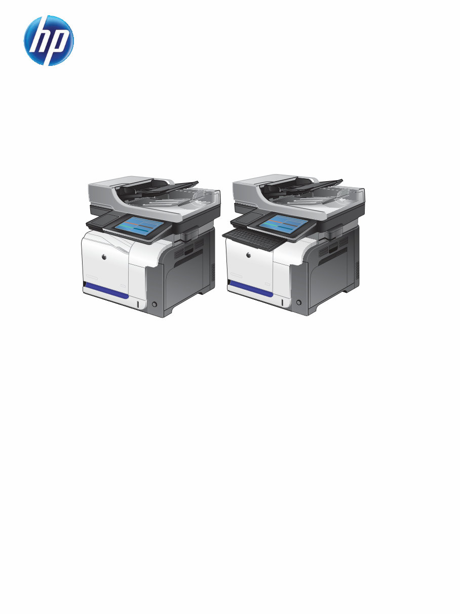
This is the complete factory Service Repair Manual for the HP LaserJet Enterprise 500 color MFP M575 Printers and HP LaserJet Enterprise 500 color flow MFP M575 Printers. This Service Manual has easy-to-read text sections with top quality diagrams and instructions as well as step-by-step instructions for repairing your HP machine. It makes it easy for you to learn technical theory, installation, maintenance, troubleshooting, disassembly, assembly, and repair of HP products.
Models Covered:
HP LaserJet Enterprise 500 color MFP M575 Printers
HP LaserJet Enterprise 500 color flow MFP M575 Printers
This Manual Covers:
Removal and replacement
Parts and diagrams
Theory of operation
Solve problems
Service and support
Product specifications
Regulatory information
Index
Model Specification: HP LaserJet Enterprise 500 color MFP M575 Printers and HP LaserJet Enterprise 500 color flow MFP M575 Printers
Total Pages: 876
File Format: PDF
Requirements: Adobe Reader
Language: English
Compatible: All Versions of Windows & Mac, APP ISO, iPhone, iPad, Android etc...
This manual is in PDF format. The Service Manual is fully indexed and bookmarked by topic. This is an original Adobe document which equals Perfect Quality and Perfect Printing. The PDF can be searched quickly to find what you need to know in every Chapter. You can print the Entire manual or ANY Pages you want to select. You can also Zoom in on any Diagram or Picture to easily SEE EVERY PART.
Save time and money by doing your own repairs! This manual makes any repair job easy to do with very easy to follow step-by-step instructions & pictures on all areas of repair.
All Service Repair Manuals are instant downloads, it means no shipping cost or waiting for a CD or paper manual to arrive in the mail. You will receive this manual today via instant download on completion of payment via our secure payment processor. We accept all major credit/debit cards and PayPal.
Recently Viewed
5,521,897Happy Clients
2,594,462eManuals
1,120,453Trusted Sellers
15Years in Business
Price:
Actual Price:
HP LaserJet Enterprise 500 color MFP M575 Printers and HP LaserJet Enterprise 500 color flow MFP M575 Printers Service Repair Ma