Canon Pixma IP6700D Printer service and repair manual
What's Included?
Lifetime Access
Fast Download Speeds
Online & Offline Access
Access PDF Contents & Bookmarks
Full Search Facility
Print one or all pages of your manual
PIXMA iP6600D PIXMA iP6700D SERVICE MANUAL Canon Copyright 2006, Canon U.S.A. This technical publication is the proprietary and confidential information of Canon U.S.A. which shall be retained for reference purposes by Authorized Service Facilities of Canon U.S.A. Its unauthorized use is prohibited.
I. MANUAL OUTLINE This manual consists of the following three parts to provide information necessary to service the PIXMA iP6600D: Part 1: Maintenance Information on maintenance and troubleshooting of the PIXMA iP6600D Part 2: Technical Reference New technology and technical information such as FAQ's (Frequently Asked Questions) of the PIXMA iP6600D Part 3: Appendix Block diagrams and pin layouts of the PIXMA iP6600D Reference: This manual does not provide sufficient information for disassembly and reassembly procedures. Refer to the graphics in the separate Parts Catalog.
II. TABLE OF CONTENTS Part 1: MAINTENANCE 1. MAINTENANCE 1 - 1. Adjustment, Periodic Maintenance, Periodic Replacement Parts, and Replacement Consumables by Service Engineer 1 - 2. Customer Maintenance 1 - 3. Product Life 1 - 4. Special Tools 1 - 5. Serial Number Location 2. LIST OF ERROR DISPLAY / INDICATION 2 - 1. Operator Call Errors 2 - 2. Service Call Errors 2 - 3. Other Error Messages 2 - 4. Warnings 2 - 5. Troubleshooting by Symptom 3. REPAIR 3 - 1. Notes on Service Part Replacement (and Disassembling / Reassembling) 3 - 2. Special Notes on Repair Servicing 3 - 3. Adjustment / Settings (1) Paper feed motor adjustment (2) Grease application (3) Waste ink counter setting (4) User mode (5) Service mode Service test print EEPROM initialization Waste ink counter reset Destination settings Button and LCD test 3 - 4. Verification Items (1) Service test print (2) EEPROM information print 4. PRINTER TRANSPORTATION Part 2: TECHNICAL REFERENCE 1. NEW TECHNOLOGIES 2. CLEANING MODE AND AMOUNT OF INK PURGED 3. PRINT MODE 3 - 1. Resolution in Printing via Computer 3 - 2. Resolution in Borderless Printing 3 - 3. Resolution in Duplex Printing
3 - 4. Resolution in Camera Direct Printing 3 - 5. Resolution in Card Direct Printing 4 . FAQ (Problems Specific to the iP6600D and Corrective Actions) Part 3: APPENDIX 1. BLOCK DIAGRAM 2. CONNECTOR LOCATION AND PIN LAYOUT 2 - 1. Logic Board Ass'y 2 - 2. Print Beam Board 2 - 3. Card Slot Board (Card Slot Unit) 2 - 4. Operation Panel Board 2 - 5. Carriage Board (Print Head Connector) 3. PIXMA iP6600D SPECIFICATIONS 4. PRINT MEDIA SPECIFICATIONS
Part 1 MAINTENANCE
1. MAINTENANCE 1-1. Adjustment, Periodic Maintenance, Periodic Replacement Parts, and Replacement Consumables by Service Engineer (1) Adjustment Note: DO NOT loosen the red screws at both ends of the carriage shaft, securing the print head position, as they are not re-adjustable. *1: Only for CD / DVD printing supported regions. *2: The red screws securing the paper feed motor may be loosened only at replacement of the paper feed motor unit. (2) Periodic maintenance No periodic maintenance is necessary. (3) Periodic replacement parts There are no parts in this printer that require periodic replacement by a service engineer. (4) Replacement consumables Adjustment Timing Purpose Tool Approx. time EEPROM initialization (EEPROM settings) At logic board ass'y replacement To initialize settings other than the following: - USB serial number - Destination setting - Waste ink counter - CD / DVD correction value None. 1 min. Destination settings (EEPROM settings) At logic board ass'y replacement To set the destination. None. Perform in the service mode. 1 min. LCD language settings At logic board ass'y replacement To set the language to be displayed on the LCD. None. 1 min. Waste ink counter resetting (EEPROM settings) - At logic board replacement - At waste ink absorber replacement To reset the waste ink counter. None. Perform in the service mode. 1 min. CD / DVD detection sensor light volume correction *1 - At logic board replacement - At carriage unit replacement To correct the light volume for the CD / DVD detection sensor. None. (Automatically performed in the service test print) 2 min. Ink system function check - At logic board replacement - At platen unit replacement - At carriage unit replacement To maintain detection functionality for presence of the ink tanks and each ink tank position. None. Perform in the service mode. 1 min. Paper feed motor position adjustment *2 At paper feed motor replacement To adjust the belt tension. (Position the paper feed motor so that the belt is stretched tight.) None. 5 min. Grease application - At carriage unit replacement - At PR shaft ass'y replacement - At CL base or CL gear replacement - To maintain sliding properties of the carriage shaft and the lift cam shaft. - To protect the printer's sliding portions (gears). - FLOIL KG- 107A (QY9- 0057) 1 min. 1-1
There are no consumables that require replacement by a service engineer. 1-2. Customer Maintenance 1-3. Product Life (1) Printer Specified print volume (I) or the years of use (II), whichever comes first. (I) Print volume: 10,000 pages (II) Years of use: 5 years of use Adjustment Timing Purpose Tool Approx. time Print head alignment At print head replacement. To ensure accurate dot placement. - Printer buttons (automatic / manual) - Computer (automatic settings via the printer driver) 3 min. Print head cleaning When print quality is not satisfying. To improve nozzle conditions. - Printer buttons - Computer (settings via the printer driver) 1 min. Print head deep cleaning When print quality is not satisfying, and not improved by print head cleaning. To improve nozzle conditions. - Printer buttons - Computer (settings via the printer driver) 2 min. Ink tank replacement When an ink tank becomes empty. (No ink error) ----- ----- 2 min. Paper feed roller cleaning When paper does not feed properly. To clean the paper feed rollers. Printer buttons 2 min. CD / DVD print position adjustment At CD / DVD printing, when necessary. To correct CD / DVD print position. Computer (application software) 5 min. Bottom plate cleaning When the back side of the paper is smeared. To clean the platen ribs. - Printer buttons - Computer (settings via the printer driver) 1 min. LCD contrast adjustment When the LCD contrast is not desirable. To set the desirable contrast. - Printer buttons 1 min. ASF sub- roller cleaning When the paper fed from the ASF is smeared due to ink mist attached to the ASF sub-rollers. To clean the ASF sub-rollers. - Plain paper - Printer buttons (paper feed roller cleaning) 1 min. Black 1,500 character pattern 2,000 pages Color A4, 7.5% duty per color pattern 1,500 pages A4, photo, borderless printing 1,500 pages 4 x 6, photo, borderless printing 4,500 pages Postcard, photo, borderless printing 500 pages 1-2
(2) Print head Print volume: 10,000 pages (3) Ink tank (target value) Black 1,500 character pattern 2,000 pages Color A4, 7.5% duty per color pattern 1,500 pages A4, photo, borderless printing 1,500 pages 4 x 6, photo, borderless printing 4,500 pages Postcard, photo, borderless printing 500 pages Pattern Ink tank used Print yield Black text CLI-8BK Approx. 480 pages Color chart CLI-8BK Approx. 970 pages CLI-8Y Approx. 460 pages CLI-8M Approx. 520 pages CLI-8C Approx. 760 pages Photo chart CLI-8BK Approx. 1,500 pages CLI-8Y Approx. 320 pages CLI-8M Approx. 670 pages CLI-8C Approx. 1,000 pages CLI-8PM Approx. 140 pages CLI-8PC Approx. 200 pages Black text: When printing the Canon standard pattern (1,500 characters per page) on A4 size plain paper, with the default settings in the Windows XP driver, using Word 2003. Color chart: When printing the ISO/JIS-SCID N5 pattern on A4 size plain paper in bordered printing, with the default settings in the Windows XP driver, using Photoshop 7.0. Photo chart: When printing the Canon standard pattern on 4" x 6" Photo Paper Plus Glossy in borderless printing, with the default settings in the Windows XP driver, using Windows XP Photo Printing Wizard. The print yield in the table above is an average value measured in continuous printing, using the ink tank immediately after it is unsealed, until the ink is out. Ink yield may vary depending on texts and photos printed, application software, print mode, and type of paper used. When the printer is turned on and while printing, each ink may be used for protecting the print head and maintaining print quality. 1-4. Special Tools Name Tool No. Application Remarks FLOIL KG- 107A QY9-0057- 000 To be applied to the sliding portions of the carriage shaft and lift cam shaft. In common with the S500 and S520. 1-3
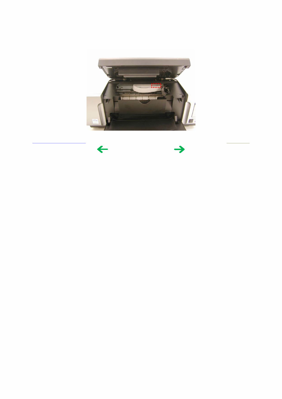
1-5. Serial Number Location On the carriage flexible cable holder (visible on the left of the carriage after the printer is turned on, and the panel cover is opened). To the table of contents To the top <Part 1: 1. MAINTENANCE> 1-4
Get the service manual for the Canon Pixma IP6700D printer. This manual features bookmarked chapters for easy navigation, allowing you to quickly find exact repair service procedures. Throughout each chapter, you'll find notes, cautions, and warnings pinpointing critical service information. Numbered instructions will guide you through every repair procedure in a step-by-step fashion, while bold figured numbers help you quickly match illustrations with instructions. Detailed illustrations, exploded diagrams, drawings, and photos will guide you through every service repair procedure. The numbered table of contents is easy to use, enabling you to find the information you need fast.
Manual Language: English
File Format: PDF
File Delivery: Instant
Pages: 58
To purchase this repair manual, simply click on the green instant button at the upper left-hand corner of this page. After purchasing, download it to your computer to save and print pages whenever you need them.
Recently Viewed
5,521,897Happy Clients
2,594,462eManuals
1,120,453Trusted Sellers
15Years in Business
Price:
Actual Price:
Canon Pixma IP6700D Printer service and repair manual