

Aficio CL7100 Service Manual
What's Included?
Fast Download Speeds
Online & Offline Access
Access PDF Contents & Bookmarks
Full Search Facility
Print one or all pages of your manual

Model J-P3
(Machine Code: G106)
SERVICE MANUAL
Subject to change
20 February 2004

!IMPORTANT SAFETY NOTICES
PREVENTION OF PHYSICAL INJURY
1. Before disassembling or assembling parts of the printer and peripherals,
make sure that the printer power cord is unplugged.
2. The wall outlet should be near the printer and easily accessible.
3. If any adjustment or operation check has to be made with exterior covers off
or open while the main switch is turned on, keep hands away from electrified
or mechanically driven components.
4. The printer drives some of its components when it completes the warm-up
period. Be careful to keep hands away from the mechanical and electrical
components as the printer starts operation.
5. The inside and the metal parts of the fusing unit become extremely hot while
the printer is operating. Be careful to avoid touching those components with
your bare hands.
HEALTH SAFETY CONDITIONS
Toner and developer are non-toxic, but if you get either of them in your eyes by
accident, it may cause temporary eye discomfort. Try to remove with eye drops
or flush with water as first aid. If unsuccessful, get medical attention.
OBSERVANCE OF ELECTRICAL SAFETY STANDARDS
1. The printer and its peripherals must be serviced by a customer service
representative who has completed the training course on those models.
2. The NVRAM module (option) installed on the controller has a lithium battery
which can explode if replaced incorrectly. Replace the NVRAM only with an
identical one. The manufacturer recommends replacing the entire NVRAM.
Do not recharge or burn this battery. Used NVRAM must be handled in
accordance with local regulations.
3. The optional fax and memory expansion units contain lithium batteries,
which can explode if replaced incorrectly. Replace only with the same or an
equivalent type recommended by the manufacturer. Do not recharge or burn
the batteries. Used batteries must be handled in accordance with local
regulations.
SAFETY AND ECOLOGICAL NOTES FOR DISPOSAL
1. Do not incinerate toner bottles or used toner. Toner dust may ignite suddenly
when exposed to an open flame.
2. Dispose of used toner, the maintenance unit which includes developer or the
organic photoconductor in accordance with local regulations. (These are
non-toxic supplies.)
3. Dispose of replaced parts in accordance with local regulations.
4. When keeping used lithium batteries in order to dispose of them later, do not
put more than 100 batteries per sealed box. Storing larger numbers or not
sealing them apart may lead to chemical reactions and heat build-up.
5. Dispose of used fusing oil in accordance with local regulations.
LASER SAFETY
The Center for Devices and Radiological Health (CDRH) prohibits the repair of
laser-based optical units in the field. The optical housing unit can only be repaired
in a factory or at a location with the requisite equipment. The laser subsystem is
replaceable in the field by a qualified Customer Engineer. The laser chassis is not
repairable in the field. Customer engineers are therefore directed to return all
chassis and laser subsystems to the factory or service depot when replacement of
the optical subsystem is required.
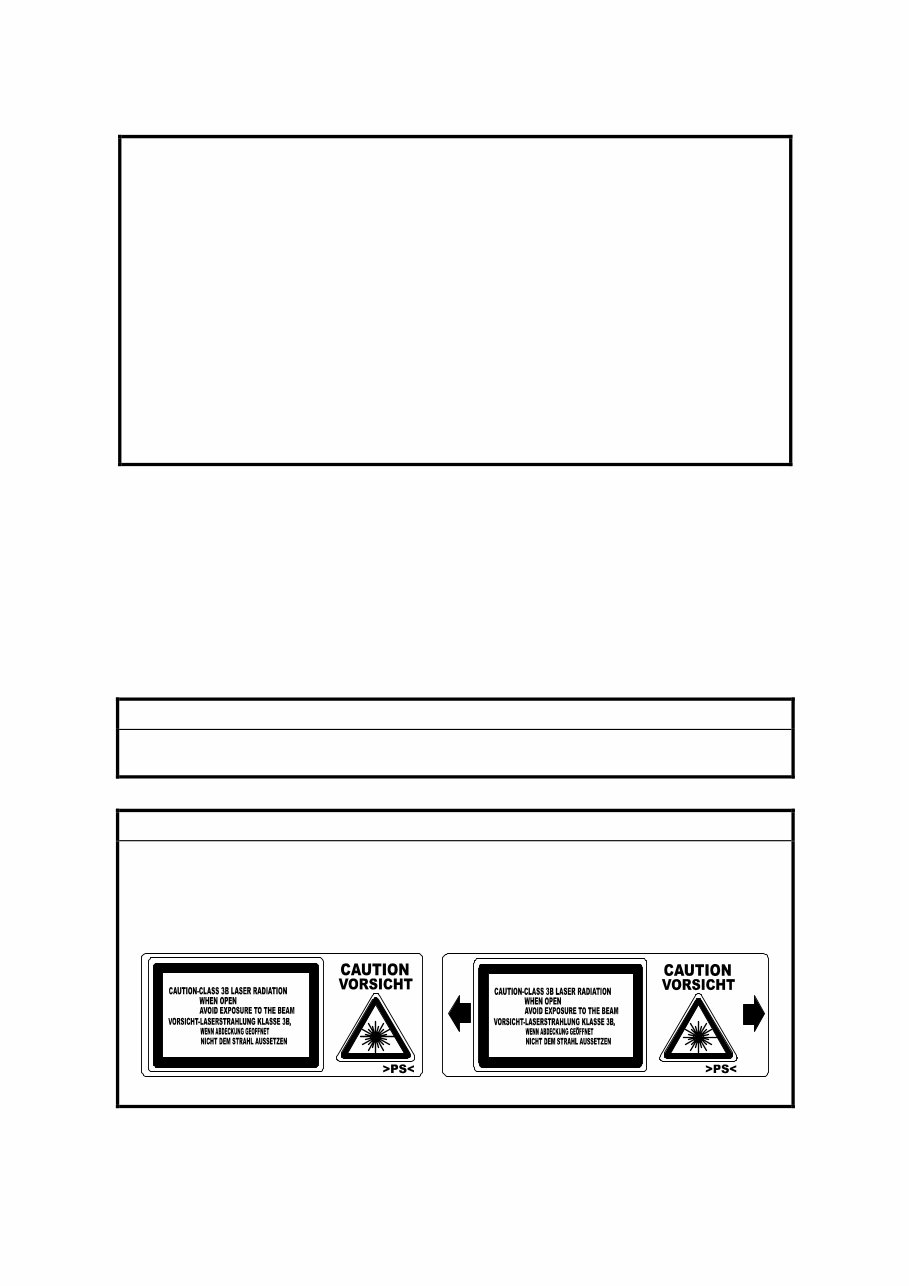
!WARNING
Use of controls, or adjustment, or performance of procedures other than
those specified in this manual may result in hazardous radiation exposure.
!WARNING
WARNING: Turn off the main switch before attempting any of the
procedures in the Laser Optics Housing Unit section. Laser
beams can seriously damage your eyes.
CAUTION MARKING:
Trademarks
Microsoft
fi
, Windows
fi
, and MS-DOS
fi
are registered trademarks of Microsoft
Corporation in the United States and /or other countries.
PostScript
fi
is a registered trademark of Adobe Systems, Incorporated.
PCL
fi
is a registered trademark of Hewlett-Packard Company.
Ethernet
fi
is a registered trademark of Xerox Corporation.
PowerPC
fi
is a registered trademark of International Business Machines
Corporation.
Other product names used herein are for identification purposes only and may be
trademarks of their respective companies. We disclaim any and all rights involved
with those marks.
Symbols and Abbreviations
This manual uses the symbols and abbreviations shown below.
Symbol Meaning
☛ Refer to section number
! Clip ring
" Screw
# Connector
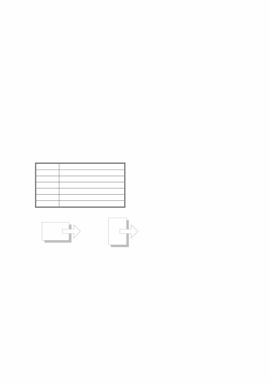
SEF Short Edge Feed
LEF Long Edge Feed
Long Edge Feed (LEF) Short Edge Feed (SEF)

i
TABLE OF CONTENTS
1. INSTALLATION........................................................................... 1-1
1.1 INSTALLATION REQUIREMENTS........................................................... 1-1
1.1.1 ENVIRONMENT .............................................................................. 1-1
1.1.2 MACHINE LEVEL ............................................................................ 1-1
1.1.3 MACHINE SPACE REQUIREMENT ................................................ 1-2
Printer .................................................................................................. 1-2
Printer and Finisher .............................................................................. 1-2
1.1.4 POWER REQUIREMENTS.............................................................. 1-3
1.2 OPTIONAL UNIT COMBINATIONS.......................................................... 1-4
1.3 PRINTER .................................................................................................. 1-5
1.3.1 POWER SOCKETS FOR PERIPHERALS....................................... 1-5
1.3.2 INSTALLATION FLOW CHART ....................................................... 1-6
1.3.3 INSTALLATION AND SETTINGS .................................................... 1-7
1.3.4 MOVING THE MACHINE................................................................. 1-8
1.3.5 TRANSPORTING THE MACHINE ................................................... 1-9
After Machine Test ............................................................................... 1-9
Transporting Used Machine ................................................................. 1-9
Necessary Adjustment ......................................................................... 1-9
Preparing the Printer .......................................................................... 1-10
1.4 OPTIONAL UNIT .................................................................................... 1-12
1.4.1 TWO-TRAY FINISHER .................................................................. 1-12
Accessory Check ............................................................................... 1-12
Installation Procedure ........................................................................ 1-12
1.4.2 PUNCH UNIT ................................................................................. 1-18
Accessory Check ............................................................................... 1-18
Installation Procedure ........................................................................ 1-19
1.4.3 BOOKLET FINISHER .................................................................... 1-22
Accessory Check ............................................................................... 1-22
Adjusting the Height ........................................................................... 1-23
Main Body .......................................................................................... 1-24
1.4.4 OPTIONAL PUNCH UNIT .............................................................. 1-27
Accessory Check ............................................................................... 1-27
Installation Procedure ........................................................................ 1-27
2. PREVENTIVE MAINTENANCE ................................................... 2-1
2.1 USER MAINTENANCE ............................................................................. 2-1
Maintenance Kit ................................................................................... 2-1
PM Alert Display................................................................................... 2-1
New Unit Detection .............................................................................. 2-1
PM Table.............................................................................................. 2-2
2.2 SERVICE MAINTENANCE ....................................................................... 2-3
PM Counter Reset................................................................................ 2-3
PM Table.............................................................................................. 2-3

ii
3. REPLACEMENT AND ADJUSTMENT ........................................ 3-1
3.1 MODEL J-P3 AND MODEL J-P2 .............................................................. 3-1
3.2 SPECIAL TOOLS ..................................................................................... 3-1
3.3 LASER OPTICS........................................................................................ 3-2
3.3.1 CAUTION DECAL LOCATIONS ...................................................... 3-2
3.3.2 LASER OPTICS HOUSING UNIT .................................................... 3-3
3.3.3 POLYGON MIRROR MOTOR ......................................................... 3-7
3.3.4 POLYGON MIRROR MOTOR DRIVE BOARD ................................ 3-8
3.3.5 LASER SYNCHRONIZING DETECTOR BOARDS ......................... 3-8
3.4 PAPER FEED ........................................................................................... 3-9
3.4.1 REGISTRATION SENSOR AND RELAY SENSORS ...................... 3-9
3.4.2 BY-PASS FEED CLUTCH ............................................................. 3-10
3.4.3 PAPER FEED MOTOR .................................................................. 3-10
3.5 TRANSFER AND PAPER TRANSPORT UNIT ...................................... 3-11
3.5.1 TRANSFER UNIT .......................................................................... 3-11
3.5.2 TRANSFER BELT CLEANING UNIT ............................................. 3-12
3.5.3 CLEANING BLADE AND CLEANING ROLLER............................. 3-12
3.5.4 TRANSFER UNIT DRIVE MOTOR ................................................ 3-14
3.6 ID SENSORS.......................................................................................... 3-15
3.7 FUSING .................................................................................................. 3-16
3.7.1 CLEANING UNIT ........................................................................... 3-16
3.7.2 PRESSURE ROLLER .................................................................... 3-17
3.7.3 FUSING UNIT FAN ........................................................................ 3-19
3.8 ELECTRICAL COMPONENTS ............................................................... 3-20
3.8.1 CONTROLLER AND BCU ............................................................. 3-20
3.8.2 NVRAM REPLACEMENT PROCEDURE ...................................... 3-22
NVRAM on the BCU........................................................................... 3-22
NVRAM on the Controller ................................................................... 3-23
NVRAMs on the BCU and Controller ................................................. 3-24
3.8.3 HIGH VOLTAGE SUPPLY BOARD ............................................... 3-25
3.8.4 CIRCUIT BREAKER AND PSU FAN ............................................. 3-26
3.8.5 CHOKE COIL ................................................................................. 3-26
3.8.6 DEVELOPMENT DRIVE MOTOR-K .............................................. 3-27
3.8.7 WASTE TONER VIBRATOR ......................................................... 3-28
4. TROUBLESHOOTING................................................................. 4-1
4.1 MODEL J-P3 AND MODEL J-P2 .............................................................. 4-1
4.2 PROCESS CONTROL ERROR CONDITIONS ........................................ 4-1
4.2.1 DEVELOPER INITIALIZATION RESULT......................................... 4-1
4.2.2 PROCESS CONTROL SELF-CHECK RESULT .............................. 4-2
4.2.3 LINE POSITION ADJUSTMENT RESULT....................................... 4-3
SC Code Classification ........................................................................ 4-4
4.3 SC TABLE ................................................................................................ 4-5
4.4 TROUBLESHOOTING GUIDE ............................................................... 4-15
4.4.1 IMAGE QUALITY ........................................................................... 4-15
4.4.2 COLOR SHIFT ............................................................................... 4-16
Adjustment Standard.......................................................................... 4-18
Preparation......................................................................................... 4-18

iii
4.4.3 BLACK OVER PRINT .................................................................... 4-20
Black Over Print Enabled ................................................................... 4-20
Black Over Print Disabled .................................................................. 4-20
4.5 BLOWN FUSE CONDITIONS................................................................. 4-21
Main PSU ........................................................................................... 4-21
Sub PSU ............................................................................................ 4-21
BCU ................................................................................................... 4-21
4.6 LEDS (BCU) ........................................................................................... 4-22
5. SERVICE TABLES ...................................................................... 5-1
5.1 SERVICE PROGRAM MODE ................................................................... 5-1
5.1.1 HANDLING SERVICE PROGRAM MODE....................................... 5-1
Starting SP Mode ................................................................................. 5-1
Selecting a Service Program................................................................ 5-2
Changing a Setting............................................................................... 5-2
Quitting SP Mode ................................................................................. 5-2
Enabling Settings ................................................................................. 5-2
Line Position Adjustment ...................................................................... 5-2
5.1.2 REMARKS ....................................................................................... 5-3
Abbreviations and Symbols.................................................................. 5-3
Possible Values.................................................................................... 5-3
Process Speed ..................................................................................... 5-4
5.2 CONTROLLER SERVICE MODE ............................................................. 5-5
5.2.1 SERVICE MODE TABLE ................................................................. 5-5
5.2.2 BIT SWITCH PROGRAMMING ....................................................... 5-7
5.3 ENGINE SERVICE MODE........................................................................ 5-8
5.3.1 SERVICE MODE TABLE ................................................................. 5-8
SP1-XXX (Feed) .................................................................................. 5-8
SP2-XXX (Drum) ................................................................................ 5-15
SP3-XXX (Process)............................................................................ 5-26
SP5-XXX (Mode)................................................................................ 5-33
SP6-XXX (Peripherals) ...................................................................... 5-47
SP7-XXX (Data Log) .......................................................................... 5-48
SP8-XXX (Data Log 2) ....................................................................... 5-55
5.3.2 MEMORY CLEAR/COUNTER CLEAR .......................................... 5-65
5.3.3 INPUT CHECK TABLE .................................................................. 5-66
Table 1: Paper Height Sensor ............................................................ 5-68
Table 2: Paper Size Switch (Tray 2)................................................... 5-68
Table 3: Paper Size (By-pass Table) ................................................. 5-69
5.3.4 OUTPUT CHECK TABLE .............................................................. 5-70
5.3.5 TEST PATTERN (SP5-997) ........................................................... 5-74
5.4 FIRMWARE UPDATE............................................................................. 5-75
5.4.1 TYPE OF FIRMWARE ................................................................... 5-75
5.4.2 PRECAUTIONS ............................................................................. 5-75
Handling SD Cards ............................................................................ 5-75
Upload or Download........................................................................... 5-75
Network Connection ........................................................................... 5-75

iv
5.4.3 FILE ARRANGEMENT .................................................................. 5-76
How the Program Works .................................................................... 5-76
Example ............................................................................................. 5-76
5.4.4 UPDATING .................................................................................... 5-77
Procedure........................................................................................... 5-77
Error Handling .................................................................................... 5-78
Power Failure ..................................................................................... 5-78
5.4.5 NVRAM DATA UPLOAD/DOWNLOAD.......................................... 5-79
Uploading NVRAM Data .................................................................... 5-79
Downloading NVRAM Data ................................................................ 5-80
5.4.6 ERROR CODE TABLE .................................................................. 5-81
5.5 SD CARD APPLI MOVE ......................................................................... 5-82
5.5.1 OVERVIEW.................................................................................... 5-82
5.5.2 MOVE EXEC.................................................................................. 5-83
5.5.3 UNDO EXEC.................................................................................. 5-84
5.6 CONTROLLER SELF-DIAGNOSTICS.................................................... 5-85
5.6.1 OVERVIEW.................................................................................... 5-85
5.6.2 DETAILED SELF-DIAGNOSTICS.................................................. 5-86
5.7 USER PROGRAM MODE....................................................................... 5-87
Starting a User Program .................................................................... 5-87
Quitting a User Program .................................................................... 5-87
Menu List ........................................................................................... 5-87
5.8 DIP SWITCHES ...................................................................................... 5-88
Controller Board ................................................................................. 5-88
BCU Board ......................................................................................... 5-88
6. DETAILED DESCRIPTIONS ....................................................... 6-1
6.1 MODEL J-P3 AND MODEL J-P2 .............................................................. 6-1
6.2 OVERVIEW .............................................................................................. 6-2
6.2.1 COMPONENT LAYOUT .................................................................. 6-2
6.2.2 DRIVE LAYOUT............................................................................... 6-3
6.2.3 BOARD STRUCTURE ..................................................................... 6-4
Overview .............................................................................................. 6-4
Descriptions ......................................................................................... 6-5
6.3 LASER EXPOSURE ................................................................................. 6-7
6.3.1 OVERVIEW...................................................................................... 6-7
6.3.2 OPTICAL PATH ............................................................................... 6-8
6.3.3 LD SAFETY SWITCH ...................................................................... 6-9
6.4 PHOTOCONDUCTOR UNIT .................................................................. 6-10
6.4.1 OVERVIEW.................................................................................... 6-10
6.4.2 DRUM CHARGE AND QUENCHING ............................................ 6-11
6.4.3 DRUM CLEANING ......................................................................... 6-12
6.4.4 WASTE TONER COLLECTION ..................................................... 6-13
Waste Toner Path .............................................................................. 6-13
Waste Toner Vibrator ......................................................................... 6-14
6.5 PAPER FEED LINE SPEED ................................................................... 6-15
6.6 IMAGE TRANSFER AND PAPER SEPARATION .................................. 6-16
6.6.1 OVERVIEW.................................................................................... 6-16

v
6.6.2 TRANSFER BELT DRIVE.............................................................. 6-17
Drive Motor......................................................................................... 6-17
Rotation Encoder ............................................................................... 6-18
ACS (Auto Color Sensing) Mode........................................................ 6-19
6.7 FUSING .................................................................................................. 6-20
6.7.1 FUSING TEMPERATURE CONTROL ........................................... 6-20
Fusing Temperatures ......................................................................... 6-20
Temperature Corrections ................................................................... 6-21
Overheat Protection ........................................................................... 6-21
6.7.2 ENERGY SAVER MODE ............................................................... 6-22
Level 1 Energy Saver Mode ............................................................... 6-22
Level 2 Energy Saver Mode ............................................................... 6-22
6.8 CONTROLLER ....................................................................................... 6-23
6.8.1 OVERVIEW.................................................................................... 6-23
6.8.2 BOARD LAYOUT ........................................................................... 6-24
6.8.3 CONTROLLER FUNCTIONS......................................................... 6-25
Paper Output Tray.............................................................................. 6-25
Stapling .............................................................................................. 6-25
Punching ............................................................................................ 6-26
6.9 HARD DISK ............................................................................................ 6-27
PERIPHERALS
BOOKLET FINISHER (B602)
1. REPLACEMENT AND ADJUSTMENT .................................. B602-1
1.1 REGULAR TRAY ................................................................................ B602-1
1.2 COVERS............................................................................................. B602-1
1.2.1 FRONT COVER ......................................................................... B602-1
1.2.2 REAR COVER ........................................................................... B602-3
1.2.3 LEFT/RIGHT TOP AND TRAY UPPER COVER........................ B602-3
1.2.4 UPPER RIGHT COVER............................................................. B602-5
1.3 SIDE GUIDE ....................................................................................... B602-6
Removal ......................................................................................... B602-6
Reassembly ................................................................................... B602-6
1.4 STAPLER UNIT .................................................................................. B602-7
Removal ......................................................................................... B602-7
Adjusting the Stapler Gear Phase ................................................ B602-10
1.5 FOLDING UNIT ................................................................................ B602-13
Removal ....................................................................................... B602-13
Adjusting the Folding Unit Gear Phase ........................................ B602-15
1.6 STACK TRAY AND JOGGER FENCE.............................................. B602-16
1.6.1 STACK TRAY UNIT ................................................................. B602-16
1.6.2 JOGGER FENCE UNIT ........................................................... B602-18
1.7 STAPLER MOTOR UNIT .................................................................. B602-20
1.8 TRANSPORT.................................................................................... B602-22
1.8.1 TRANSPORT MOTOR ............................................................ B602-22

vi
1.8.2 TRANSPORT ROLLER ........................................................... B602-22
1.9 STACK TRAY ................................................................................... B602-24
1.9.1 STACK TRAY UPPER ROLLER .............................................. B602-24
1.9.2 STACK TRAY PADDLE ........................................................... B602-25
1.9.3 STACK TRAY LOWER ROLLER ............................................. B602-27
Removal ....................................................................................... B602-27
Reassembly ................................................................................. B602-29
1.10 CIRCUIT BOARD............................................................................ B602-30
1.10.1 CONTROLLER BOARD......................................................... B602-30
1.10.2 STAPLER HOME POSITION SENSOR BOARD ................... B602-30
1.11 PUNCH UNIT, MOTORS, AND CONTROLLER ............................. B602-32
1.11.1 PUNCH UNIT AND PUNCH UNIT MOTOR ........................... B602-32
1.11.2 REGISTRATION MOTOR...................................................... B602-34
1.11.3 CONTROLLER ...................................................................... B602-35
1.11.4 PHOTO SENSOR BOARD .................................................... B602-35
1.11.5 LED BOARD .......................................................................... B602-36
1.11.6 CHAD BOX FULL SENSOR BOARD AND LED BOARD ...... B602-37
1.11.7 ADJUSTMENT AND INITIALIZATION ................................... B602-38
Sensor Voltage............................................................................. B602-38
Punch Type .................................................................................. B602-39
EEPROM...................................................................................... B602-39
2. SERVICE TABLES .............................................................. B602-40
2.1 DIP SWITCH SETTINGS .................................................................. B602-40
Punch Controller Board ................................................................ B602-40
3. DETAILED DESCRIPTIONS ............................................... B602-41
3.1 GENERAL LAYOUT ......................................................................... B602-41
3.2 DRIVE ............................................................................................... B602-42
3.3 CONTROLLER ................................................................................. B602-43
3.4 STACK TRAY ................................................................................... B602-44
3.4.1 SIMPLE OUTPUT .................................................................... B602-44
Mechanism................................................................................... B602-44
Stack-Tray Belt............................................................................. B602-44
3.4.2 SORT ....................................................................................... B602-45
3.4.3 STACK ..................................................................................... B602-46
Paddle .......................................................................................... B602-46
Stack-Tray Stopper ...................................................................... B602-46
Stack-Tray Guide Mechanism ...................................................... B602-47
Stack-Tray Guide Mechanism ...................................................... B602-48
Home Position .............................................................................. B602-48
Stapler Switch .............................................................................. B602-48
Safety Feature.............................................................................. B602-48
3.4.4 JOGGER FENCE..................................................................... B602-49
Action ........................................................................................... B602-49
Drive............................................................................................. B602-49
Home Position .............................................................................. B602-49
Paper Position .............................................................................. B602-50
You're Reading a Preview
What's Included?
Fast Download Speeds
Online & Offline Access
Access PDF Contents & Bookmarks
Full Search Facility
Print one or all pages of your manual
$30.99
Viewed 36 Times Today


Secure transaction
What's Included?
Fast Download Speeds
Online & Offline Access
Access PDF Contents & Bookmarks
Full Search Facility
Print one or all pages of your manual
$30.99
This is the full RICOH Service Repair Manual for the Jupiter-P3, J-P3 (G106), Aficio CL7100, C7435n, CLP35, IPC 3535, LP235c series. The manual is (221) pages in PDF format and contains detailed pictures, diagrams, and step-by-step procedures. It is fully indexed and bookmarked by topic, allowing for quick searches within each chapter. You have the option to print the entire manual or select specific pages. Additionally, you can zoom in on any diagram or picture for a closer view of every part. This service manual is an original Adobe document, ensuring perfect quality and perfect printing.
Professional mechanics and DIY enthusiasts will find this manual invaluable for servicing and repairing the mentioned RICOH series.


