

OKI MB460, MB470, MB480, Maintenance Manual & Parts List
What's Included?
Fast Download Speeds
Online & Offline Access
Access PDF Contents & Bookmarks
Full Search Facility
Print one or all pages of your manual
1 2 3 4 5 6
Rev Date DCO No. Contents Design Approval
BOM Use for Certification Body
Approval
Check
Date
Drawing No.
Name
Design
.......................................................................................................
.......................................................................................................
Oki Data CONFIDENTIAL
MB460/MB470/MB480
Maintenance Manual
ODA/OEL/AOS
[Rev. 1]
No.01
44306601TH
MB460/MB470/MB480
Maintenance Manual
1
247
2009-09-02
Masato Yamazaki
Masato Yamazaki
Isao Kitano
Related drawings
Drawing No. Name
44306601TL MB460/MB470/MB480 Disassembly for Maintenance
44306601TR MB460 RSPL
44306621TR MB470 RSPL
44306641TR MB480 RSPL

44306601TH Rev. 1
2 /
Oki Data CONFIDENTIAL
Document Revision History
Rev.No. Date
Corrected items
Person in
charge
No. Page Description of change
1 2009-09-02 Issue PED14 M.Yamazaki

44306601TH Rev. 1
3 /
Oki Data CONFIDENTIAL
Preface
This manual explains the maintenance methods of MB460/MB470/MB480.
This manual is prepared for the maintenance person. In regard to the handling methods of MB460/
MB470/MB480, please refer to the User’s Manual.
Note! • Contents of this manual is subject to change without notice.
• While all reasonable efforts have been made to make this document as ac-
curate and helpful as possible, we make no warranty of any kind, expressed
or implied, as to the accuracy of the information contained herein. Oki Data
assumes no responsibility to the damages caused or claimed to have been
caused by the user as a result of repair, adjustment and/or change using this
manual.
• Parts of this product are delicate and can be damaged unless properly handled.
We strongly recommend the user to maintain the product at the hand of the
registered maintenance person of our company
• Before starting the maintenance work, please neutralize the static electricity.

44306601TH Rev. 1
4 /
Oki Data CONFIDENTIAL
Table of contents
1. CONFIGURATION ................................................................................................ 7
1.1 System Configuration ........................................................................................................... 7
1.2 Structure of MFP ................................................................................................................... 9
1.3 Offer of Options ................................................................................................................... 10
1.4 Specifications ...................................................................................................................... 11
1.5 Interface Specification......................................................................................................... 13
1.5.1 USB Interface Specification ................................................................................... 13
1.5.1.1 Outline of USB Interface......................................................................... 13
1.5.1.2 USB Interface Connector and Cable ...................................................... 13
1.5.1.3 UBS Interface Signal .............................................................................. 13
1.5.2 Network Interface Specification ............................................................................. 14
1.5.2.1 Outline of Network Interface ................................................................... 14
1.5.2.2 Network Interface Connector and Cable ................................................ 14
1.5.2.3 Network Interface Signal ........................................................................ 14
1.5.3 Telephone Line Interface Specification (Only MB470/MB480) ............................ 15
1.5.3.1 Outline of telephone Line Interface ........................................................ 15
1.5.3.2 Telephone Line Interface Connector and Cable..................................... 15
1.5.3.3 Telephone Line Interface signal ............................................................. 15
1.5.4 Parallel Interface Specifications ........................................................................... 16
1.5.4.1 Parallel Interface Overview .................................................................... 16
1.5.4.2 Parallel Interface Connector and Cable ................................................. 16
1.5.4.3 Parallel Interface Level .......................................................................... 16
2. OPERATIONAL EXPLANATION ........................................................................ 17
2.1 Electrophotographic process mechanism .......................................................................... 17
2.2 Printing process .................................................................................................................. 24
2.3 Toner entrance detection .................................................................................................... 28
3. MFP INSTALLATION ..........................................................................................30
3.1 Precautions and Prohibition ................................................................................................30
3.2 MFP Unpacking Procedure .................................................................................................32
3.3 MFP Installation Instructions ...............................................................................................33
3.4 Packed Units and Attachments ...........................................................................................34
3.5 Assembly Procedure ...........................................................................................................35
3.5.1 MFP Main Body .....................................................................................................35
3.5.2 Power Cable Connection .......................................................................................44
3.5.3 Installation of Optional Components .....................................................................46
3.5.4 Confirm the Recognition of Option ........................................................................ 50
3.6 Configuration Page Print ..................................................................................................... 51
3.7 Network Information Print....................................................................................................54
3.8 Connection Procedures.......................................................................................................55
3.9 Checking of User Paper ...................................................................................................... 59
4. REPLACEMENT OF PARTS ..............................................................................60
4.1 Precautions on the replacement of parts ............................................................................60
4.2 Parts layout .........................................................................................................................62

44306601TH Rev. 1
5 /
Oki Data CONFIDENTIAL
4.3 Parts replacement method .................................................................................................. 67
4.3.1 Detachment methods of the scanner and printer ..................................................68
4.3.1.1 Cover-Side-R ..........................................................................................68
4.3.1.2 Cover-Side-L ..........................................................................................69
4.3.1.3 FAX Board (In case of MB470/480 ) .................................................... 70
4.3.1.4 Detachment methods of the scanner and printer ................................... 71
4.3.2 Scanner ................................................................................................................. 73
4.3.2.1 Detachment of the paper tray ................................................................. 73
4.3.2.2 Detachment of Pad ................................................................................. 74
4.3.2.3 Removing ADF PCBA ............................................................................ 75
4.3.2.4 Removing operation panel ..................................................................... 76
4.3.2.5 Removing the MPCBA............................................................................77
4.3.2.6 Removing ADF Assembly ...................................................................... 79
4.3.2.7 Removing the Window-ADF ................................................................... 81
4.3.3 Printer ....................................................................................................................82
4.3.3.1 LED Head ...............................................................................................82
4.3.3.2 Roller-Transfer ........................................................................................83
4.3.3.3 CU Board ................................................................................................84
4.3.3.4 OP Cover Assy .......................................................................................85
4.3.3.5 MPT-Assy (In case of MB460, it is Manual-Assy) ..................................86
4.3.3.6 Front-Guide-Assy ................................................................................... 87
4.3.3.7 Roller-Assy-Feed ....................................................................................88
4.3.3.8 Guide-Paper-Duplex ...............................................................................89
4.3.3.9 Stacker-Cover-Assy ................................................................................90
4.3.3.10 Motor-DC-Main ....................................................................................... 91
4.3.3.11 Fuser-Assy..............................................................................................92
4.3.3.12 Rear-Cover-Assy ....................................................................................94
4.3.3.13 Frame-Assy-Lower .................................................................................95
4.3.3.14 High voltage / Low voltage power board ................................................ 97
4.3.3.15 Plate-Bracket-Motor................................................................................99
4.3.3.16 Roller-Back up ...................................................................................... 100
4.3.3.17 Roller-Resist ......................................................................................... 101
4.3.3.18 Lever-In-Sensor .................................................................................... 102
4.3.3.19 Lever-Eject-Sensor/Photo-Interrupter .................................................. 103
4.3.3.20 Lever-End/Lever-Duplex/Lever-Cassette/Gear-Assy-Clatch ............... 104
4.3.3.21 Paper feeding roller
(Roller-Pick-Up,Roller-Feed-NOW,Roller-Assy-MPT) .......................... 106
5. MAINTENANCE MENU .................................................................................... 108
5.1 Maintenance Menu............................................................................................................ 108
5.1.1 Boot Menu ........................................................................................................... 108
5.1.2 System Maintenance Menu ................................................................................. 111
5.1.3 Fax Maintenance Menu ....................................................................................... 115
5.1.4 Print Statistics Menu ............................................................................................ 117
5.2 Maintenance Utility ............................................................................................................ 119
5.3 Variou s printing of the MFP unit with controller................................................................ 121
5.4 Switch pressing function when power supply is turned on ............................................... 121
5.5 Settings after Parts Replacement ..................................................................................... 122
5.5.1 Notes when exchanging the main circuit board and EEPROM setting after the
exchange of 86M circuit board................................................................................. 122

44306601TH Rev. 1
6 /
Oki Data CONFIDENTIAL
6. PERIODIC MAINTENANCE.............................................................................. 126
6.1 Periodic Replacement Parts.............................................................................................. 126
6.2 Cleaning ............................................................................................................................ 126
6.3 Cleaning of LED lens array ............................................................................................... 126
6.4 Cleaning the pick-up roller ............................................................................................... 128
6.5 Cleaning the inside of the MFP ......................................................................................... 129
6.6 Cleaning the papaer path in the ADF ............................................................................... 130
6.7 Cleaning the underside of the ADF ................................................................................... 132
6.8 Cleaning the Flatbed glass................................................................................................ 132
7. TROUBLESHOOTING PROCEDURES ............................................................ 133
7.1 Precautions prior to repair ................................................................................................. 133
7.2 Items to be checked prior to taking action on abnormal images....................................... 133
7.3 Precautions when taking action on abnormal images ...................................................... 133
7.4 Preparations for troubleshooting ....................................................................................... 133
7.5 Troubleshooting method.................................................................................................... 133
7.5.1 LCD Message List ............................................................................................... 134
7.5.2 LCD Message Troubleshooting ........................................................................... 183
7.5.3 Print Troubleshooting ........................................................................................... 199
7.5.4 Response after Flash compulsive initialization.................................................... 207
7.5.5 Network Troubleshooting .....................................................................................208
7.5.5.1 Connection error occurs with the Web browser ...................................209
7.5.5.2 Print operation is not possible .............................................................. 215
7.5.5.3 Cannot create Certificate...................................................................... 216
7.5.5.4 Installation of Certificate is not possible ............................................... 216
7.5.5.5 Other questionnaires ............................................................................ 219
7.5.5.6 Restrictions when using Internet Explore 7 ..........................................222
7.5.6 Fax Error Code List ..............................................................................................223
7.6 Fuse Checking ..................................................................................................................225
8. CONNECTION DIAGRAMS ..............................................................................226
8.1 Resistance value ...............................................................................................................226
8.2 Component layout ............................................................................................................. 228
APPENDIX C MAINTENANCE MANUAL FOR SECOND TRAY UNIT..................234
1 Overview ...........................................................................................................................234
1.1 Function ......................................................................................................................234
1.2 Exterior and Parts Name ............................................................................................234
2. Description for Operation of Second Tray unit ..................................................................235
3. Part Replacement .............................................................................................................236
3.1 Precautions on replacing parts ...................................................................................236
3.2 Arrangement of Parts .................................................................................................. 237
3.3 How to Replace Parts .................................................................................................238
3.3.1 Roller-Pick-Up, Roller-Feed-Now .........................................................239
3.3.2 Guard-Connector, Connector (9715S-08Z02-G4C) ............................. 240
3.3.3 Roller-Feed ........................................................................................... 241
3.3.4 Board-OT7............................................................................................ 242
3.3.5 CONN Cord-AMP8P-AMP8P ............................................................... 243
3.3.6 Gear-Assy-Clatch ................................................................................. 244
3.3.7 Frame-Assy-Retard, Spring-Retard...................................................... 246
4. Cleaning of Paper Feed Roller and Separation Roller ...................................................... 247
44306601TH Rev. 1
/
Oki Data CONFIDENTIAL
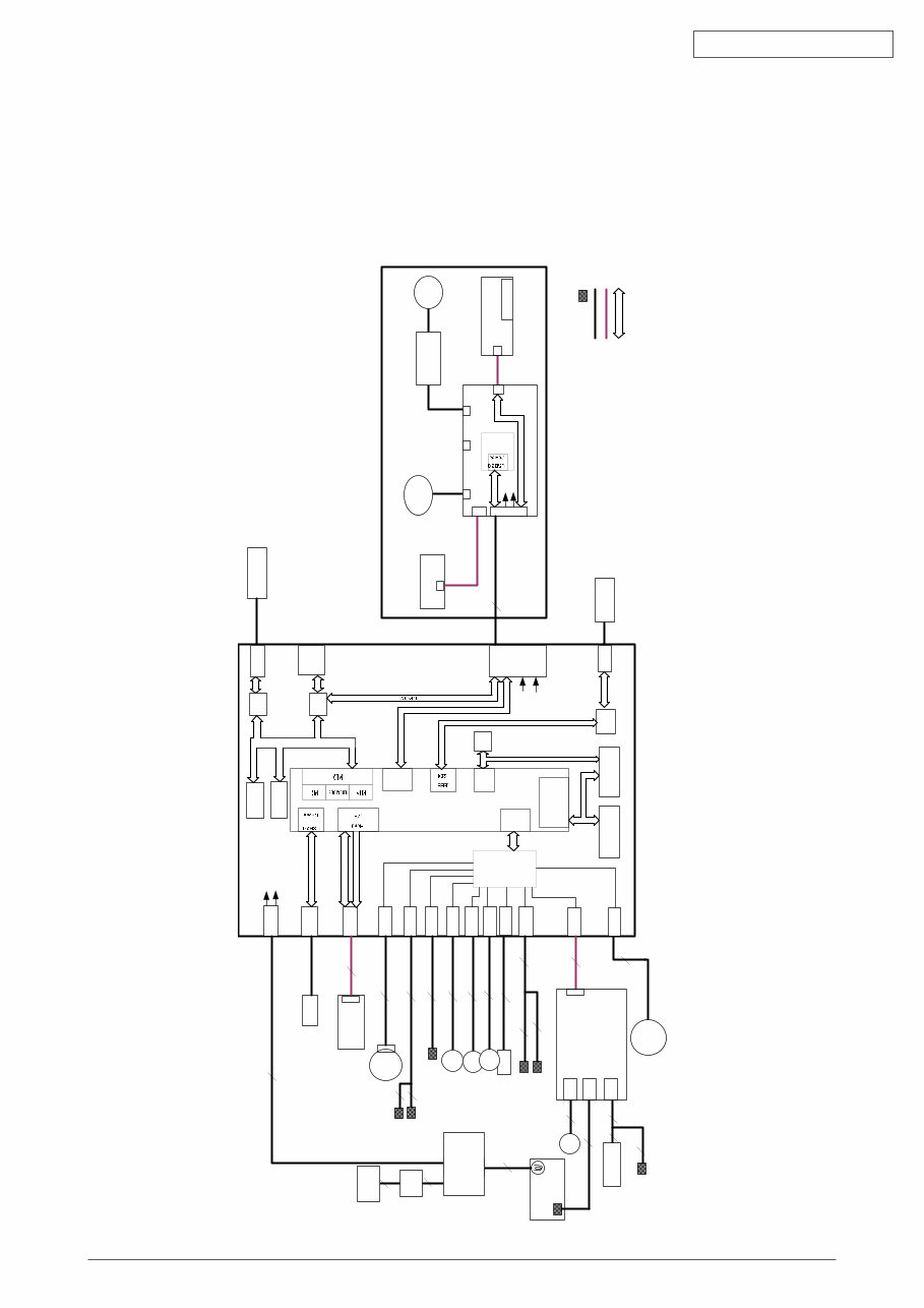
Fig. 1.1.1
1. CONFIGURATION
1.1 System Configuration
MB460
The system configuration of this product is shown in Figure 1.1.1.
DM
PE
RCLT
THERM
HCLT
MCLT
SON
HVIF
EXRCO
Fax IF
PW
HEAD
PNLUSB
LAN
USB
CENT
DC Motor
Assy.
JST2
2
JST2
2
JST2
2
clutch
clutch
AMP8
8
USB IF
Centronics IF
JST24
24
JST24
Panel PCB
LCD
FB
Moter
CCD UNIT
20
JST20
JST20
Scanner Unit
JST9
9
28 JST28
FAN
2nd
Tray
6
JST7
Board-TT1
cover open switch
JST10
3
Cover open sensor
EXIT sensor
6
3
2
JST2
Temperature sensor
IP100
ALF
UPD7
202
AMP6
JST28
CN1
CN2
CN3
High Volt PCB
3
3 5
2
FUSER UNIT
2
2
AC Inlet
AC SW
2
2
86M
SPILYTAS 2
8051
I2C
16C550
UART
LC98500B
PU LSI
DDR
I/F
10
JST10
Nor
Nand
DIMM
I2C
ROM
64 Kbit
74LVC
161284
3
3
Paper end
duplex
JST9
SCANNER
PCB
L629
SOLENOID
ພ
ROM IF
PCI
ROM IF
PCI
2NDTRAY
LED HEAD UNIT
TXD/
RXD
DP/
DM
DP/DM
HEAD IF
HEAD Clock
RS232C
DP/
DM
RS232C
PUIF
DDR-
SDRAM
64
MB
I2C
DDR IF
IEEE1284
IEEE1284
Cable
FFC
Sensor
BUS
5V
24V
5V
24V
5V
24V
JST2
2
clutch
AFD
Moter
AFD PCB
LAN IF
Power Supply PCB
44306601TH Rev. 1
/
Oki Data CONFIDENTIAL
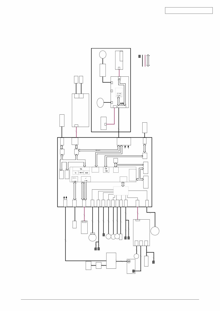
MB40/MB40
The system configuration of this product is shown in Figure 1.1.2.
Fig. 1.1.2
DM
PE
RCLT
THERM
HCLT
MCLT
SON
HVIF
EXRCO
Fax IF
PW
HEAD
PNLUSB
LAN
USB
CENT
DC Motor
Assy.
JST2
2
JST2
2
JST2
2
clutch
clutch
AMP8
8
USB IF
Centronics IF
JST24
24
JST24
FAX PCB
Panel PCB
LCD
FB
Moter
CCD UNIT
20
JST20
JST20
Scanner Unit
JST9
9
28 JST28
FAN
2nd
Tray
6
JST7
Board-TT1
cover open switch
JST12
JST10
3
Cover open sensor
EXIT sensor
6
3
2
JST2
Temperature sensor
IP100
ALF
UPD7
202
AMP6
JST28
CN1
CN2
CN3
High Volt PCB
3
3 5
2
FUSER UNIT
2
2
AC Inlet
AC SW
2
2
86M
SPILYTAS 2
8051
I2C
16C550
UART
LC98500B
PU LSI
DDR
I/F
10
JST10
Nor
Nand
JST12
12
DIMM
Line
Tel
I2C
ROM
64 Kbit
74LVC
161284
3
3
Paper end
duplex
JST9
SCANNER
PCB
L629
SOLENOID
ພ
ROM IF
PCI
ROM IF
PCI
2NDTRAY
LED HEAD UNIT
TXD/
RXD
DP/
DM
DP/DM
HEAD IF
HEAD Clock
RS232C
DP/
DM
RS232C
PUIF
DDR-
SDRAM
64
MB
I2C
DDR IF
IEEE1284
IEEE1284
Cable
FFC
Sensor
BUS
5V
24V
5V
24V
5V
24V
JST2
2
clutch
AFD
Moter
AFD PCB
LAN IF
Power Supply PCB
Line
Tel
44306601TH Rev. 1
/
Oki Data CONFIDENTIAL
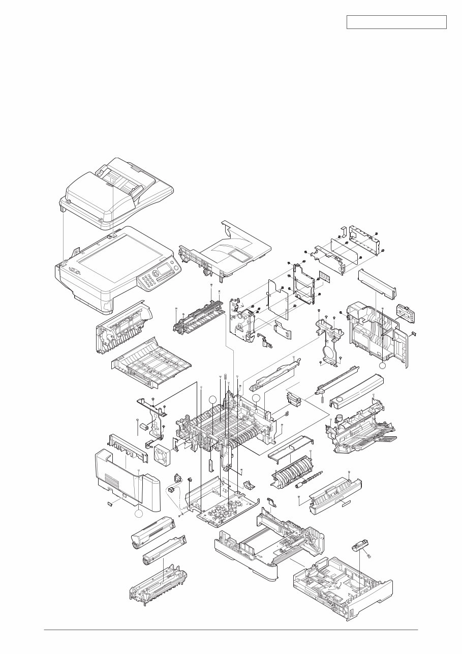
1.2 Structure of MFP
The insides of MB460/MB40/MB40 printers are composed of the following parts.
• Scanner part
• Electronic photography process part
• Paper path
• Control part (CU part/PU part)
• Power supply parts (high voltage part/low voltage part)
Figure 1.2.1 shows the composition of the MFP.
A
A
A’
A’
Fig. 1.2.1
44306601TH Rev. 1
10 /
Oki Data CONFIDENTIAL
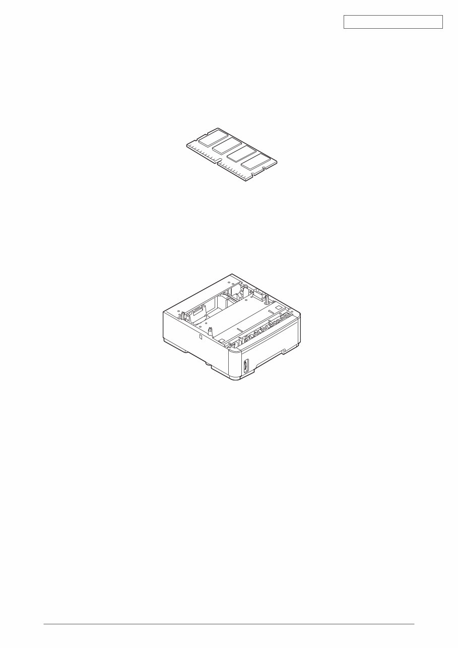
1.3 Offer of Options
This product can be installed with the following option.
(1) Additional memory board 64MB/256MB
(2) Option Tray
Fig. 1.3.1
Fig. 1.3.2
You're Reading a Preview
What's Included?
Fast Download Speeds
Online & Offline Access
Access PDF Contents & Bookmarks
Full Search Facility
Print one or all pages of your manual
$32.99
Viewed 53 Times Today


Secure transaction
What's Included?
Fast Download Speeds
Online & Offline Access
Access PDF Contents & Bookmarks
Full Search Facility
Print one or all pages of your manual
$32.99
This maintenance manual and parts list for OKI MB460, MB470, MB480 provides detailed diagrams, pictures, and procedures for diagnosing and repairing your copier. It is a valuable resource for both professional mechanics and DIY enthusiasts.
The maintenance manual includes the following content:
- CONFIGURATION
- System Configuration
- Structure of MFP
- Offer of Options
- Specifications
- Interface Specification
- USB Interface Specification
- Outline of USB Interface
- USB Interface Connector and Cable
- UBS Interface Signal
- Network Interface Specification
- Outline of Network Interface
- Network Interface Connector and Cable
- Network Interface Signal
- Telephone Line Interface Specification (Only MB470/MB480)
- Outline of telephone Line Interface
- Telephone Line Interface Connector and Cable
- Telephone Line Interface signal
- Parallel Interface Specifications
- Parallel Interface Overview
- Parallel Interface Connector and Cable
- Parallel Interface Level
- USB Interface Specification
- OPERATIONAL EXPLANATION
- Electrophotographic process mechanism
- Printing process
- Toner entrance detection
- MFP INSTALLATION
- Precautions and Prohibition
- MFP Unpacking Procedure
- MFP Installation Instructions
- Packed Units and Attachments
The maintenance manual also covers periodic maintenance, troubleshooting procedures, connection diagrams, and includes an appendix for the maintenance manual for the second tray unit.
The parts list includes detailed information for the scanner unit, ADF unit, flatbed unit, printer unit, and various assemblies for each model (MB460, MB470, MB480).
Total number of pages: 314.


