

Service Manual COMMODORE 1701/1702 MONITOR
What's Included?
Fast Download Speeds
Online & Offline Access
Access PDF Contents & Bookmarks
Full Search Facility
Print one or all pages of your manual
SERVICE MANUAL
MODEL 1701/1702 MONITOR
Preliminary
APRIL 1985 PN-314004-01
Commodore Business Machines, Inc.
1200 Wilson Drive, West Chester, Pennsylvania 19380 U.S.A.
Commodore makes no expressed or implied war-
ranties with regard to the information contained
herein. The information is made available solely on
an as is basis, and the entire risk as to quality and
accuracy is with the user. Commodore shall not be
liable for any consequential or incidental damages
in connection with the use of the information con-
tained herein. The listing of any available replace-
ment part herein does not constitute in any case
a recommendation, warranty or guaranty as to
quality or suitability of such replacement part.
Reproduction or use without expressed permission,
of editorial or pictorial content, in any matter is
prohibited.
This manual contains copyrighted and proprietary information. No part
of this publication may be reproduced, stored in a retrieval system, or
transmitted in any form or by any means, electronic, mechanical,
photocopying, recording or otherwise, without the prior written permis-
sion of Commodore Electronics Limited.
Copyright © 1985 by Commodore Electronics Limited.
All rights reserved.
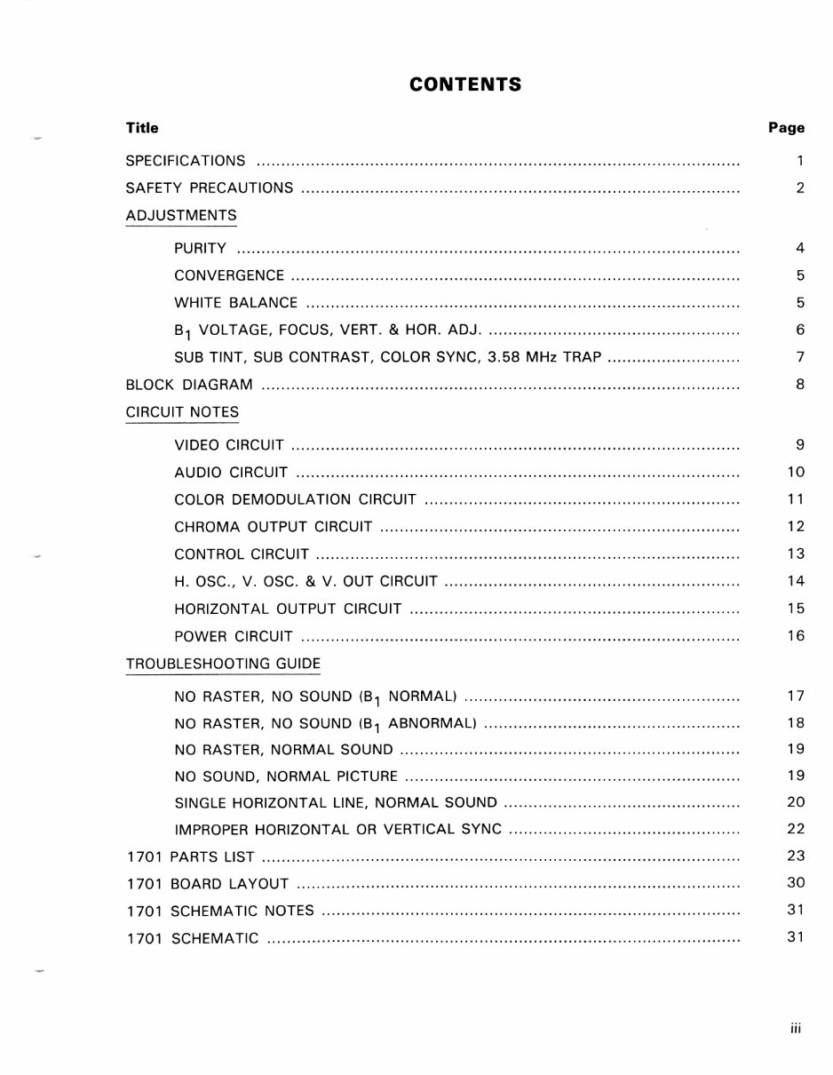
CONTENTS
Title Page
SPECIFICATIONS
SAFETY PRECAUTIONS ......................................................................................... 2
ADJUSTMENTS
PURITY ...................................................................................................... 4
CONVERGENCE ... ........................ .............. .............. ........................ .... ........ 5
WHITE BALANCE ........................................................................................ 5
B1 VOLTAGE, FOCUS, VERT. & HOR. ADJ. ................................................... 6
SUB TINT, SUB CONTRAST, COLOR SYNC, 3.58 MHz TRAP ........................... 7
BLOCK DIAGRAM
CIRCUIT NOTES
8
VIDEO CIRCUIT ....... ............ ... ................... ........ ................... ................ .... ... 9
AUDIO CIRCUIT ............ ......... .......... ........................ .... ....... .... ... ................. 10
COLOR DEMODULATION CIRCUIT ................................................................ 11
CHROMA OUTPUT CIRCUIT ................................................... ........ .... ....... ... 12
CONTROL CIRCUIT .......................................................................... ............ 13
H. OSC., V. OSC. & V. OUT CIRCUIT ................ ...................... ...................... 14
HORIZONTAL OUTPUT CIRCUIT ................................................................... 15
POWER CiRCUiT ........................................................................................ , 16
TROUBLESHOOTING GUIDE
NO RASTER, NO SOUND (81 NORMAL) .............. .......... .......... .............. ........ 17
NO RASTER, NO SOUND (81 ABNORMAL) ...... ........................ .............. ........ 18
NO RASTER, NORMAL SOUND .............................................. ' ............. , ........ 19
NO SOUND, NORMAL PICTURE ................................................. , .................. 19
SINGLE HORIZONTAL LINE, NORMAL SOUND ....... .............. ........................... 20
IMPROPER HORIZONTAL OR VERTICAL SYNC ...... ........ .......... ....................... 22
1701 PARTS LIST ........ ......................... ..... ............. .......................... ... ......... ........ 23
1701 BOARD LAYOUT ................................... ............................ .......... ........... ...... 30
1701 SCHEMATIC NOTES ..................................................................................... 31
1701 SCHEMATIC ................................................................................................ 31
iii
.-----~-~--~------
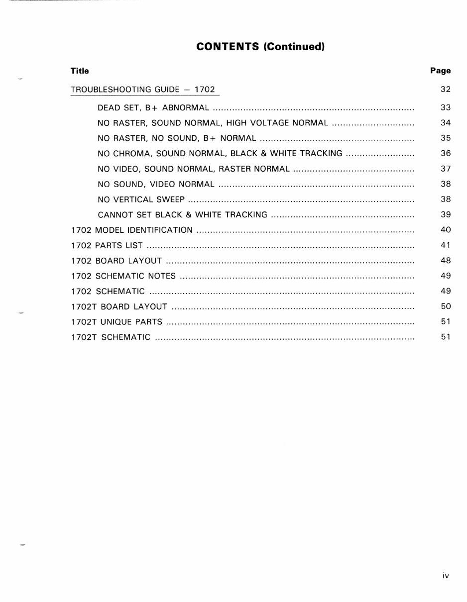
CONTENTS (Continued)
Title Page
TROUBLESHOOTING GUIDE - 1702 32
DEAD SET, B+ ABNORMAL ......................................................................... 33
NO RASTER, SOUND NORMAL, HIGH VOLTAGE NORMAL .............................. 34
NO RASTER, NO SOUND, B+ NORMAL ........................................................ 35
NO CHROMA, SOUND NORMAL, BLACK & WHITE TRACKING ......................... 36
NO VIDEO, SOUND NORMAL, RASTER NORMAL ...................... ...................... 37
NO SOUND, VIDEO NORMAL ....................................................................... 38
NO VERTICAL SWEEP .................................................................................. 38
CANNOT SET BLACK & WHITE TRACKING .................................................... 39
1702 MODEL IDENTIFICATION ............................................................................... 40
1702 PARTS LIST ................................................................................................. 41
1702 BOARD LAYOUT .......................................................................................... 48
1 702 SCHEMATIC NOTES ..................................................................................... 49
1702 SCHEMATIC ................................................................................................ 49
1 702T BOARD LAYOUT ........................................................................................ 50
1702T UNIQUE PARTS .......................................................................................... 51
1702T SCHEMATIC .............................................................................................. 51
iv
GENERAL DESCRIPTION
C1701/C1702 COLOR MONITORS
PRODUCT SPECIFICATION
The C1701 and C1702 are quality, high resolution color monitors, designed to maximize the video
capabilities of your Commodore Computer. They give you a superior color picture that enhances your
computing experience and are completely compatible with all Commodore equipment.
SCREEN SIZE
13 Inch (screen measured diagonally). NTSC color standard
DISPLAY
40 Columns x 25 lines
RESOLUTION
1000 Characters per screen
CONTROLS
Color, tint, brightness, contrast, volume, vertical hold and horizontal hold
AUDIO
Built-in audio amplifier and speaker
INPUTS
Chrominance, luminance, composite video and audio
OTHER FEATURES
Video cassette recorder compatible (1 V p-p, 75 Ohms)
COMPUTERS
Commodore 64, VIC 20, Plus/4 and C16
POWER REQUIREMENTS
120 Volts, 60 Hz, 0.85 Amps
POWER CONSUMPTION
87 Watts
All specifications subject to change without notice.
1
SAFETY PRECAUTIONS
1 . This product contains special designed circuits and components that were designed for safety
purposes.
For continued protection, changes should not be made to the original design unless authorized
in writing by the manufacturer. Replacement parts must be identical to those used in the original
circuits. Service should be performed by qualified personnel only.
2. Alterations to the design or circuitry of this receiver should not be made. Any design alterations
or additions will void the manufactuer's warranty and will further relieve the manufacturer of
responsibility for personal injury or property damage resulting therefrom.
3. Many electrical and mechanical parts in MONITOR sets have special safety-related characteristics.
These characteristics are often not evident from visual inspection nor can the protection afforded
by them necessarily be obtained by using replacement components rated for higher voltage, watt-
age, etc. Replacement parts which have these special safety characteristics are identified in the
parts list of this service manual. Electrical components having such features are identified by
shading on the schematics and by (*) on the parts list in this service manual. The use of a substitute
replacement which does not have the same safety characteristics as the recommended
replacement part shown in the parts list may create shock, fire, or other hazards.
4. If any repair has been made to the chassis, it is recommended the the B1 setting be checked
or adjusted (See ADJUSTMENT OF B1 VOLTAGE).
5. The high voltage applied to the picture tube must conform with that specified in this service manual.
Excessive high voltage can cause an increase in X-Ray emission, arcing and possible component
damage, therefore operation under excessive high voltage conditions should be kept to a minimum,
or should be prevented. If severe arcing occurs, remove the AC power immediately and deter-
mine the cause by visual inspection (incorrect installation, cracked or melted high voltage harness,
poor soldering, etc.). To maintain the proper minimum level of soft X-Ray emission, components
in the high voltage circuitry including the picture tube, must be the exact replacements or alter-
natives approved by the manufacturer of the complete product.
6. Do not check high voltage by drawing an arc. Use a high voltage meter or a high voltage probe
with a VTVM. Discharge the picture tube before attempting meter connection by connecting a
clip lead to the ground frame and connecting the other end of the lead through a 1 OkQ 2W resistor
to the anode button.
7. When service is required, observe the original lead dress. Extra precaution should be given to
assure correct lead dress in the high voltage circuit area. Where a short circuit has occurred,
those components that indicate evidence of overheating should be replaced. Always use the
manufacturer's replacement components.
2
SAFETY PRECAUTIONS (Continued)
8. ISOLATION CHECK (SAFETY FOR ELECTRICAL SHOCK HAZARD)
After re-assembling the product, always perfrom an isolation check on the exposed metal parts
of the cabinet, screwheads, cable jacks, controls shafts, etc., to be sure the product is safe to
operate without danger of electrical shock.
(A) DIELECTRIC STRENGTH TEST
The isolation between the AC primary circuit and all metal parts exposed to the user, par-
ticularly any exposed metal part having a return path to the chassis should withstand a voltage
of 1,1 OOV AC (r.m.s.) for a period of one second.
This method of test requires test equipment not generally found in the service trade. *
(8) LEAKAGE CURRENT CHECK
*
Plug the AC line cord directly into the AC outlet (do not use a line isolation transformer dur-
ing this check). Using a "Leakage Current Tester", measure the leakage current from each
exposed metal part of the cabinet, particularly any exposed metal part having a return path
to the chassis, to a known good earth ground (water pipe, etc.). Any leakage current must
not exceed 0.5mA.
ALTERNATE CHECK METHOD
Plug the AC line cord directly into the AC output (do not use a line isolation transformer
during this check). Use an AC voltmeter having 1,000 ohms per volt or more sensitivity in
the following manner. Connect a 15000 10W resistor paralleled by a 0.15/LF AC-type
capacitor between an exposed metal part and a known good earth ground (water pipe, etc.).
Measure the AC voltage across the resistor with the AC voltmeter.
Move the resistor connection to each exposed metal part, particularly any exposed metal
part having a return path to the chassis, and measure the AC voltage across the resistor.
Now, reverse the plug in the AC outlet and repeat each measurement. Any voltage measured
must not exceed 0.35V AC (r.m.s). This corresponds to 0.5mA AC (r.m.s.).
CAUTION:
When troubleshooting, with power applied, use an isolation transformer and confirm that
the CRT earth wire is connected to the CRT socket board and the chassis.
3
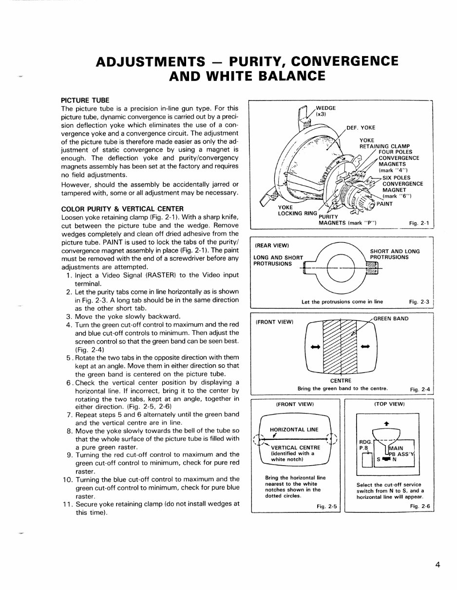
ADJUSTMENTS - PURITY, CONVERGENCE
AND WHITE BALANCE
PICTURE TUBE
The picture tube is a precision in-line gun type. For this
picture tube, dynamic convergence is carried out by a preci-
sion deflection yoke which eliminates the use of a con-
vergence yoke and a convergence circuit. The adjustment
of the picture tube is therefore made easier as only the ad-
justment of static convergence by using a magnet is
enough. The deflection yoke and purity/convergency
magnets assembly has been set at the factory and requires
no field adjustments.
However, should the assembly be accidentally jarred or
tampered with, some or all adjustment may be necessary.
COLOR PURITY & VERTICAL CENTER
Loosen yoke retaining clamp (Fig. 2-1). With a sharp knife,
cut between the picture tube and the wedge. Remove
wedges completely and clean off dried adhesive from the
picture tube. PAINT is used to lock the tabs of the purity/
convergence magnet assembly in place (Fig. 2-1). The paint
must be removed with the end of a screwdriver before any
adjustments are attempted.
1. Inject a Video Signal (RASTER) to the Video input
terminal.
2. Let the purity tabs come in line horizontally as is shown
in Fig. 2-3. A long tab should be in the same direction
as the other short tab.
3. Move the yoke slowly backward.
4. Turn the green cut-off control to maximum and the red
and blue cut-off controls to minimum. Then adjust the
screen control so that the green band can be seen best.
(Fig. 2-4)
5 . Rotate the two tabs in the opposite direction with them
kept at an angle. Move them in either direction so that
the green band is centered on the picture tube.
6 . Check the vertical center position by displaying a
horizontal line. If incorrect, bring it to the center by
rotating the two tabs, kept at an angle, together in
either direction. (Fig. 2-5, 2-6)
7. Repeat steps 5 and 6 alternately until the green band
and the vertical centre are in line.
8. Move the yoke slowly towards the bell of the tube so
that the whole surface of the picture tube is filled with
a pure green raster.
9. Turning the red cut-off control to maximum and the
green cut-off control to minimum, check for pure red
raster.
10. Turning the blue cut-off control to maximum and the
green cut-off control to minimum, check for pure blue
raster.
11. Secure yoke retaining clamp (do not install wedges at
this time).
YOKE
LOCKING RING PURITY
MAGNETS (mark "P") Fig. 2-1
(REAR VIEW)
LONG AND SHORT
PROTRUSIONS
Let the protrusions come in line
Fi g .2- 3 J
(FRONT VIEW)
_-o--7"7t7::,.,-_.L GREEN BAN D
CENTRE
Bring the green band to the centre.
Fig. 2-4
(FRONT VIEW)
HORIZONTAL LINE
(~~--'------------~
(identified with a
white notch)
Bring the horizontal line
nearest to the white
notches shown in the
dotted circles.
Fig. 2-5
(TOP VIEW)
RDG.
IJL-___ --I
Select the cut-off service
switch from N to S, and a
horizontal line will appear.
Fig. 2-6
4
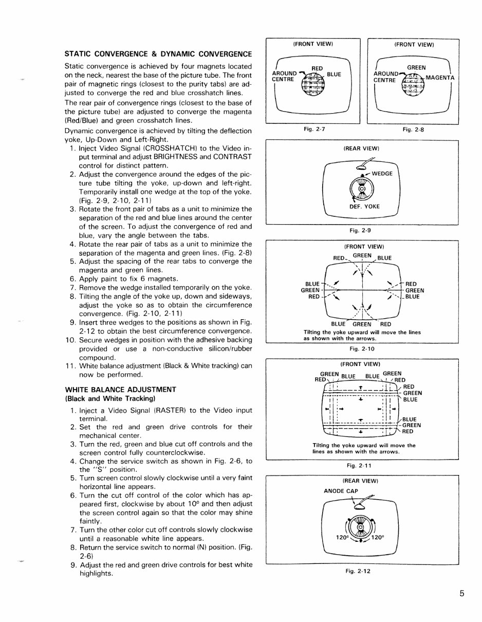
STATIC CONVERGENCE & DYNAMIC CONVERGENCE
Static convergence is achieved by four magnets located
on the neck, nearest the base of the picture tube. The front
pair of magnetic rings (closest to the purity tabs) are ad-
justed to converge the red and blue crosshatch lines.
The rear pair of convergence rings (closest to the base of
the picture tube) are adjusted to converge the magenta
(Red/Blue) and green crosshatch lines.
Dynamic convergence is achieved by tilting the deflection
yoke, Up-Down and Left-Right.
1. Inject Video Signal (CROSSHATCH) to the Video in-
put terminal and adjust BRIGHTNESS and CONTRAST
control for distinct pattern.
2. Adjust the convergence around the edges of the pic-
ture tube tilting the yoke, up-down and left-right.
Temporarily install one wedge at the top of the yoke.
(Fig. 2-9, 2-10, 2-11)
3. Rotate the front pair of tabs as a unit to minimize the
separation of the red and blue lines around the center
of the screen. To adjust the convergence of red and
blue, vary the angle between the tabs.
4. Rotate the rear pair of tabs as a unit to minimize the
separation of the magenta and green lines. (Fig. 2-8)
5. Adjust the spacing of the rear tabs to converge the
magenta and green lines.
6. Apply paint to fix 6 magnets.
7. Remove the wedge installed temporarily on the yoke.
8. Tilting the angle of the yoke up, down and sideways,
adjust the yoke so as to obtain the circumference
convergence. (Fig. 2-10, 2-11)
9. Insert three wedges to the positions as shown in Fig.
2-12 to obtain the best circumference convergence.
10. Secure wedges in position with the adhesive backing
provided or use a non-conductive siliconlrubber
compound.
11. White balance adjustment (Black & White tracking) can
now be performed.
WHITE BALANCE ADJUSTMENT
(Black and White Tracking)
1. Inject a Video Signal (RASTER) to the Video input
terminal.
2. Set the red and green drive controls for their
mechanical center.
3. Turn the red, green and blue cut off controls and the
screen control fully counterclockwise.
4. Change the service switch as shown in Fig. 2-6, to
the "S" position.
5. Turn screen control slowly clockwise until a very faint
horizontal line appears.
6. Turn the cut off control of the color which has ap-
peared first, clockwise by about 10
0
and then adjust
the screen control again so that the color may shine
faintly.
7. Turn the other color cut off controls slowly clockwise
until a reasonable white line appears.
8. Return the service switch to normal (N) position. (Fig.
2-6)
9. Adjust the red and green drive controls for best white
highlights.
(FRONT VIEW) (FRONT VIEW)
RED
AROUND~. BLUE
CENTRE '
, ,
~
1ROUND-~ G~.EEN \
CENTRE __ :': MAGENTA
I
-•.. - I
' .... , "
"------
Fig. 2·7 Fig. 2-8
BLUE
GREEN -
RED -
-
(REAR VIEW)
W
,..WEDGE
0)
!
"
DEF. YOKE
Fig. 2-9
(FRONT VIEW)
RED.
GREEN
BLUE ,
, I "
"
/'f" ,,~,
.. ......
-
/~ I
"
./-',
'\.,\j
/1 ' . "-
BLUE GREEN RED
RED
- GREEN
_BLUE
Tilting the yoke upward will move the lines
as shown with the arrows.
Fig. 2-10
(FRONT VIEW)
GREEN BLUE BLUE GREEN
RED, ; , ! /RED
; I ; l' ' 1 ' RED
__ ::::-_:_-=--=~=-:.:_:~ __ :_ -::: GREEN
I I : + : I' BLUE
..,Ii:'" .,.' I ..
I • ' I
--t l.- ____ = _____ Jl. -~~~~N
~r.----~--'-:- +- RED
Tilting the yoke upward will move the
lines as shown with the arrows.
Fig. 2-11
(REAR VIEW)
ANODE CAP
Fig, 2-12
5
NOTE: 1702 locations in ( ).
B1 VOLTAGE - Inject a video signal
1701 (110V)
Regulate VR, R109, for B1 adjustment so that Dc voltage between TP-91 and earth is 110 volts.
1702 (125V.)
Confirm that the voltage at TP-94 and IC901 pin 4 is 125 volts.
NOTE: Meter should be periodically calibrated at 20K ohms/volt.
FOCUS
Adjust the FOCUS control for best overall definition and picture detail at normal brightness and contrast.
VERTICAL POSITION
Adjust the V. center VR R428 (R429) to the optimum vertical picture position.
VERTICAL HEIGHT AND LINEARITY
1 . Display a pattern which allows easy confirmation of symmetry (such as a circle or crosshatch).
2. Reduce the vertical size with the V. HEIGHT VA.
3. Adjust the vertical linearity with the V. LIN. VA.
4. Readjust the vertical height, so that the picture extends to normal size.
HORIZONTAL WIDTH
Adjust H. WIDTH control coil L503 (L522) by turning it with a hexagonal adjusting bar only if RIGHT
and LEFT sides of picture can't be seen.
HORIZONTAL OSCILLATOR
1. Set the H. FREQ. VR to the mechanical center position.
2. Connect a jumper clip between TP-33A and TP-33B.
3. While rotating the H. FREQ. VR, R504, keep the picture stationary or slowly moving.
4. Remove the jumper wire.
5. Make sure that the set maintains horizontal sync, when signals are switched.
6
You're Reading a Preview
What's Included?
Fast Download Speeds
Online & Offline Access
Access PDF Contents & Bookmarks
Full Search Facility
Print one or all pages of your manual
$30.99
Viewed 52 Times Today


Secure transaction
What's Included?
Fast Download Speeds
Online & Offline Access
Access PDF Contents & Bookmarks
Full Search Facility
Print one or all pages of your manual
$30.99
Looking to repair your COMMODORE 1701/1702 MONITOR? Save on mechanic fees with our comprehensive repair manual, suitable for professional mechanics and DIY enthusiasts alike. This manual provides detailed specifications, safety precautions, adjustments, block diagrams, circuit notes, troubleshooting guides, and more, spanning 100 pages. Available in English, the manual is compatible with both Windows and Mac operating systems. With printable pages, you can conveniently bring the manual to your home, office, or repair shop. It's packed with diagrams and pictures, making it easy to understand and follow. Skip the wait for CD ROMs – order now and get instant access.


