Safety regulations 3 General This quick overview summarises important regulations − structured according to focal points − to provide the knowledge required to prevent accidents involving personal injury of damage to property and the envi- ronment. Additional information can be found in the operating manual for the engine. Important: Should an accident occur despite all the precautionary measures, in particular due to contact with caustic acid, fuel penetrating the skin, scalding by hot oil, splashes of antifreeze in the eyes etc., consult a doctor immediately. 1. Instructions for avoiding accidents likely to cause injury Inspection, adjustment and repair work may only be performed by authorised and skilled person- nel. D Moor the ship at the pier! D Secure the power units on removal. D The engine may only be started and operated by authorised personnel. D When the engine is running, do not enter the engine room. Should it be unavoidable to enter the engine room when the engine is running, remain at a safe distance from rotating parts. Wear tight-fitting working clothes. Use ear protection. D Do not touch the engine with your bare hands when it is at operating temperature: danger of burns. D Keep vicinity of engine, ladders and stairways free of oil and grease. D Only work with tools in perfect condition. Damaged or widened wrenches slip: danger of injury. D It is not permitted that any persons remain beneath an engine hanging on a crane hook. Maintain lifting gear in good working order. D Only open the coolant circuit when the engine has cooled down. If opening is unavoida- ble with the engine at operating temperature, follow the instructions in the chapter “Maintenance and care” in operating manual.
Safety regulations 4 D Neither tighten nor open pipes and hoses that are under pressure (lube oil circuit, coo- lant circuit and any downstream hydraulic oil circuit): danger of injury due to fluids flowing out. D When testing the injection nozzles, do not place your hand under the fuel jet. Do not inhale fuel vapours. D During work on the electrical system or battery, as a general principle always discon- nect the battery or switch off the battery master switch. D Do not use the quick charger to jump start the engine! Only quick-charge the batteries with the positive and negative cables disconnected! D Only disconnect the batteries with the “ignition” switched off. D Observe the manufacturer’s regulations for handling batteries. Caution: battery acid is toxic and caustic. Battery gases are explosive. D Only perform voltage measurements with suitable measurement devices! The input resistance of a measuring device should be at least 10 MW. D Only plug in or unplug wiring harness plugs for electronic control units when the “ignition” is switched off! For electric welding, disconnect the batteries; connect the positive with the negative cable electrically. Earth the welding equipment as closely as possible to the weld. Do not place the cables of the welding equipment parallel to electrical cables in the vehicle. For other measures regarding accident prevention, please read the “Information sheets for welders”. D During painting work, only expose electronic components to high temperatures (max. 85°C) for short periods; at a maximum of 70°C, a duration of up to approx. 2 hours is permitted: disconnect batteries.
Safety regulations 5 Limitation of liability for parts and accessories In your own interest, we recommend that you use only accessories and original MAN parts for your MAN engine that have been expressly approved by MAN. For these accessories and parts, the reliability, safety and suitability have been especially determined for MAN engines. Despite continuous market observation, we are unable to assess other products − even if in individual cases they have been officially inspected and approved − and cannot be held liable for the quality. Laying up or storage If engines are laid up or placed in storage for more than 3 months, special measures in accordance with MAN factory standard M 3069, part 3, are required.
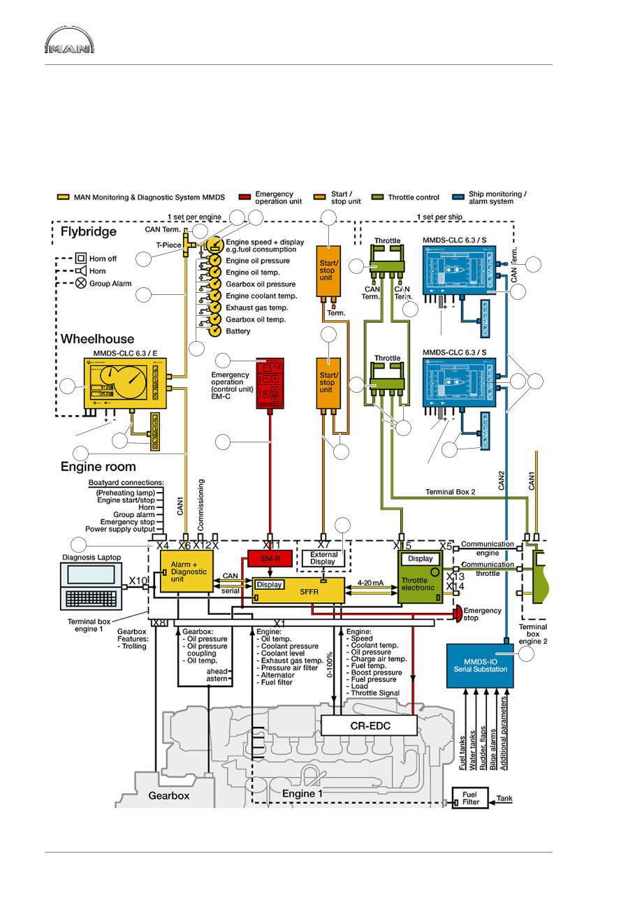
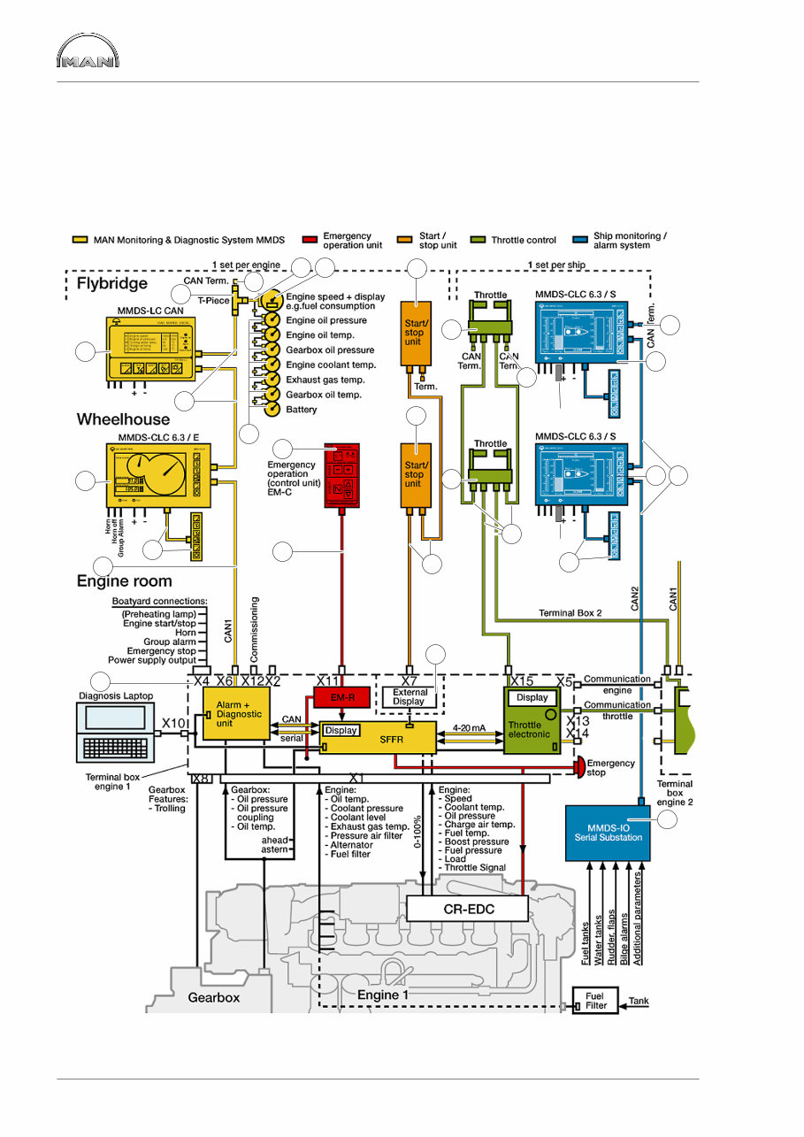
Layout of MAN Monitoring Diagnostic System (MMDS) 6 D28-CR: MMDS for CR engines with EDC 7 (CAN bus system) / CLC display, step 1 (on bridge) − Throttle lever system MPC − Ship alarm system (step 1) − Emergency running unit Explanation of step 1: CLC display with a CAN interface (1x input, 1x output) 1 2 2 3 5 8 9 16 16 12 10 7 6 11 12 14 14 15 18 19 13 2 6 6 GPS GPS 17 ext. power supply ext. power supply 23 4
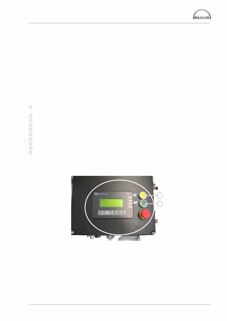
Layout of MAN Monitoring Diagnostic System (MMDS) 7 The D28-CR CAN bus system consists of the following components: À Terminal box with − SFFR 51.25805−700X − Motherboard 51.25430−200X − Diagnostic and monitoring unit − Receiver unit for emergency running unit (Em-R) 51.27720−7013, optional − MPC throttle lever control (51.11610−6033) Á CAN bus cable 51.25411−0025 / −0026 / −0015 / −0016 / −0017 Â CLC 6.3 display engine (CAN / step 1) (51.27721−7043) Ã Connection lead 51.25449−0022 with key block 51.27720−7025 Ä T-piece for separating the CAN line 51.25433−0023 Å CAN termination resistor 51.25435−0174 Æ Adapter CAN master 51.25411−6014 Ç CAN master tachometer with display for engine parameters (51.27102−7002) È CAN slave instruments É Emergency running unit (Em-C) control box (51.27720−7035), optional 1 1 Connection cable for terminal box (15 m, 20 m) − emergency running unit Em-R (51.24449−0047 / −0048) 1 2 Start-stop unit * 1 3 Connection cable * 1 4 CAN throttle lever 51.11605−6050 (long) / −6051 (short) 1 5 Connecting cable 51.25449−0052 / −0053 / −0054 / −0055 1 6 MMDS-CLC display, ship 1 7 Connection lead 51.25449−0022 with key block 51.27720−7025 1 8 Serial substation IO12 (In / Out12), order-based 1 9 CAN bus cable 51.25411−0025 / −0026 / −0015 / −0016 / −0017 2 3 Engine room panel (optional) as of 11.2005 − LC display in the terminal box cover − SFFR without display − Button for ignition À “ON / OFF” / engine Á “START / STOP” integrated in the terminal box cover 1 2 * in planning NB: The validity of the item numbers refers to the issue date of these instructions.
Layout of MAN Monitoring Diagnostic System (MMDS) 8 D28-CR: MMDS for CR engines with EDC 7 (CAN bus system) / LC-CAN on flybridge − Throttle lever system MPC − Ship alarm system (step 1) − Emergency running unit 1 2 3 5 8 9 16 16 12 10 7 6 11 12 14 14 15 18 19 13 20 2 GPS GPS 23 17 6 6 4
This service repair manual is an essential resource for anyone working with the Man Marine Diesel Engine Common Rail R6 V8 V10 V12 Series. It provides detailed diagrams and instructions for servicing and repairing the engine, as well as checking and interfacing with various components. Whether you're a professional mechanic or a DIY enthusiast, this manual is a valuable tool.
The manual covers a wide range of topics, including safety regulations, the layout of the MAN Monitoring Diagnostic System (MMDS), system description, engine terminal box, monitored variables, gearbox sensors and alarm configuration, sensors, diagnostic unit MMDS in the terminal box, motherboard, commissioning, connecting cables, service and commissioning tools, MMDS-CR, and circuit diagrams for various models and years.
With instant access to the manual, you can save on postage and packaging. It is compatible with all versions of Windows and Mac, and the language used is English. The file format is PDF, and it can be viewed using Adobe Reader. This comprehensive manual will help you save time and money while gaining a deeper understanding of your Man Marine Diesel Engine.
Recently Viewed
5,521,897Happy Clients
2,594,462eManuals
1,120,453Trusted Sellers
15Years in Business
Price:
Actual Price:
Man Monitoring Diagnostic System Marine Diesel Engine Common Rail R6 V8 V10 V12 Series Workshop Service Repair Manual (