

COMMODORE C64 C64C Service Repair Fix Manual
What's Included?
Fast Download Speeds
Online & Offline Access
Access PDF Contents & Bookmarks
Full Search Facility
Print one or all pages of your manual
SERVICE MANUAL
C64/C64C
MARCH, 1992 PN-314001-03
Commodore Business Machines, Inc.
1200 Wilson Drive, West Chester, Pennsylvania 19380 U.S.A.
Commodore makes no express or implied warranties
with regard to the information contained herein. The
information is made available solely on an as is basis,
and the entire risk as to completeness, reliability, and
accuracy is with the user. Commodore shall not be
liable for any damages in connection with the use of
the information contained herein. The listing of any
available replacement part herein does not constitute
in any case a recommendation, warranty or guaranty
as to quality or suitability of such replacement part.
Reproduction or use without express permission, of
editorial or pictorial content, in any matter is prohibited.
This manual contains copyrighted and proprietary information. No part
of this publication may be reproduced, stored in a retrieval system, or
transmitted in any form or by any means, electronic, mechanical, photo
copying, recording or otherwise, without the prior written permission
of Commodore Electronics Limited.
Copyright © 1992 by Commodore Electronics Limited.
All rights reserved. Printed in U.S.A.
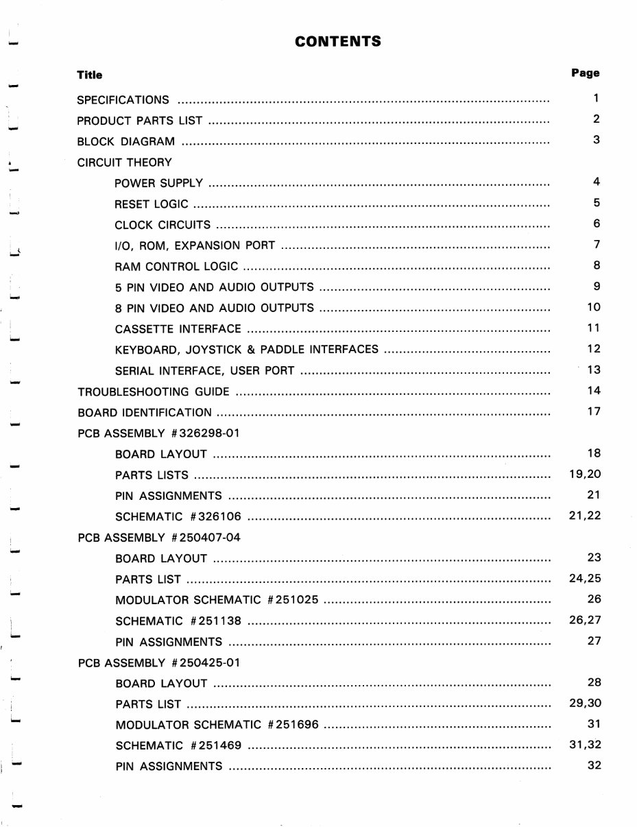
CONTENTS
Title Page
SPECIFICATIONS 1
PRODUCT PARTS LIST 2
BLOCK DIAGRAM 3
CIRCUIT THEORY
POWER SUPPLY 4
RESET LOGIC 5
CLOCK CIRCUITS 6
I/O, ROM, EXPANSION PORT 7
RAM CONTROL LOGIC 8
5 PIN VIDEO AND AUDIO OUTPUTS 9
8 PIN VIDEO AND AUDIO OUTPUTS 10
CASSETTE INTERFACE 11
KEYBOARD, JOYSTICK & PADDLE INTERFACES 12
SERIAL INTERFACE, USER PORT 13
TROUBLESHOOTING GUIDE 14
BOARD IDENTIFICATION 17
PCB ASSEMBLY #326298-01
BOARD LAYOUT 18
PARTS LISTS 19,20
PIN ASSIGNMENTS 21
SCHEMATIC #326106 21,22
PCB ASSEMBLY #250407-04
BOARD LAYOUT 23
PARTS LIST 24,25
MODULATOR SCHEMATIC #251025 26
SCHEMATIC #251138 26,27
PIN ASSIGNMENTS 27
PCB ASSEMBLY #250425-01
BOARD LAYOUT 28
PARTS LIST 29,30
MODULATOR SCHEMATIC #251696 31
SCHEMATIC #251469 31,32
PIN ASSIGNMENTS 32
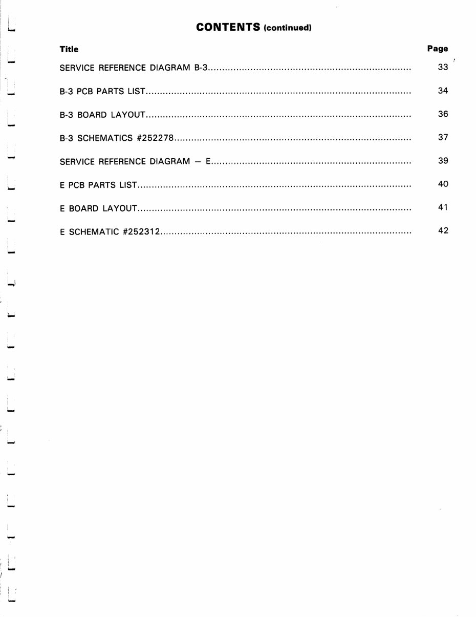
CONTENTS (continued)
Title Page
SERVICE REFERENCE DIAGRAM B-3 33
B-3 PCB PARTS LIST 34
B-3 BOARD LAYOUT 36
B-3 SCHEMATICS #252278 37
SERVICE REFERENCE DIAGRAM - E 39
E PCB PARTS LIST 40
E BOARD LAYOUT 41
E SCHEMATIC #252312 42
C64
GENERAL DESCRIPTION
MEMORY
ROM
MICROPROCESSOR
DISPLAY
COLORS
CHARACTERS
DISPLAY MODES
RESOLUTION
SPRITES
SOUND
KEYBOARD
KEYS
INPUTS/OUTPUTS
FEATURES
PERIPHERALS
POWER REQUIREMENTS
COMPUTER
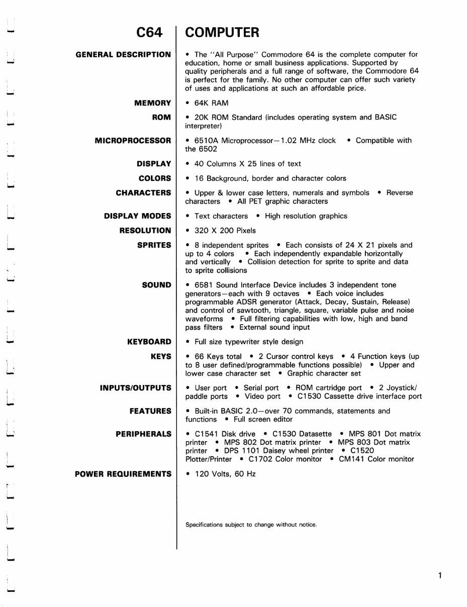
• The "All Purpose" Commodore 64 is the complete computer for
education, home or small business applications. Supported by
quality peripherals and a full range of software, the Commodore 64
is perfect for the family. No other computer can offer such variety
of uses and applications at such an affordable price.
• 64K RAM
• 20K ROM Standard (includes operating system and BASIC
interpreter)
• 6510A Microprocessor—1.02 MHz clock • Compatible with
the 6502
• 40 Columns X 25 lines of text
• 16 Background, border and character colors
• Upper & lower case letters, numerals and symbols • Reverse
characters • All PET graphic characters
• Text characters • High resolution graphics
• 320 X 200 Pixels
• 8 independent sprites • Each consists of 24 X 21 pixels and
up to 4 colors • Each independently expandable horizontally
and vertically • Collision detection for sprite to sprite and data
to sprite collisions
• 6581 Sound Interface Device includes 3 independent tone
generators—each with 9 octaves • Each voice includes
programmable ADSR generator (Attack, Decay, Sustain, Release)
and control of sawtooth, triangle, square, variable pulse and noise
waveforms • Full filtering capabilities with low, high and band
pass filters • External sound input
• Full size typewriter style design
• 66 Keys total • 2 Cursor control keys • 4 Function keys (up
to 8 user defined/programmable functions possible) • Upper and
lower case character set • Graphic character set
• User port • Serial port • ROM cartridge port • 2 Joystick/
paddle ports • Video port • C1530 Cassette drive interface port
• Built-in BASIC 2.0—over 70 commands, statements and
functions • Full screen editor
• C1541 Diskdrive • C1530 Datasette • MPS 801 Dot matrix
printer • MPS 802 Dot matrix printer • MPS 803 Dot matrix
printer • DPS 1101 Daisey wheel printer • C1520
Plotter/Printer • C1702 Color monitor • CM 141 Color monitor
• 120 Volts, 60 Hz
Specifications subject to change without notice.
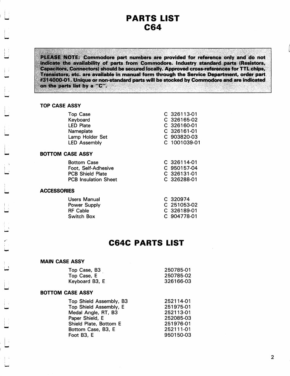
PARTS LIST
C64
NOTE: Commodore part numbers are provided tor reference only and do not
_._ availability of parts from Commodore. Industry standard parts (Resistors,
"', Connectors) should be secured locally. Approved cross-references tor TTL chips,
are available in manual form through the Service Department, order part
1. Unique or non-standard parts will be stocked by Commodore and are indicated
bya"C".
TOP CASE ASSY
L
Top Case
Keyboard
LED Plate
Nameplate
Lamp Holder Set
LED Assembly
BOTTOM CASE ASSY
Bottom Case
Foot, Self-Adhesive
PCB Shield Plate
PCB Insulation Sheet
ACCESSORIES
Users Manual
Power Supply
RF Cable
Switch Box
C
C
C
C
C
C
326113-01
326165-02
326160-01
326161-01
903820-03
1001039-01
C 326114-01
C 950157-04
C 326131-01
C 326288-01
C 320974
C 251053-02
C 326189-01
C 904778-01
C64C PARTS LIST
MAIN CASE ASSY
Top Case, B3
Top Case, E
Keyboard B3, E
BOTTOM CASE ASSY
Top Shield Assembly, B3
Top Shield Assembly, E
Medal Angle, RT, B3
Paper Shield, E
Shield Plate, Bottom E
Bottom Case, B3, E
Foot B3, E
250785-01
250785-02
326166-03
252114-01
251975-01
252113-01
252085-03
251976-01
252111-01
950150-03
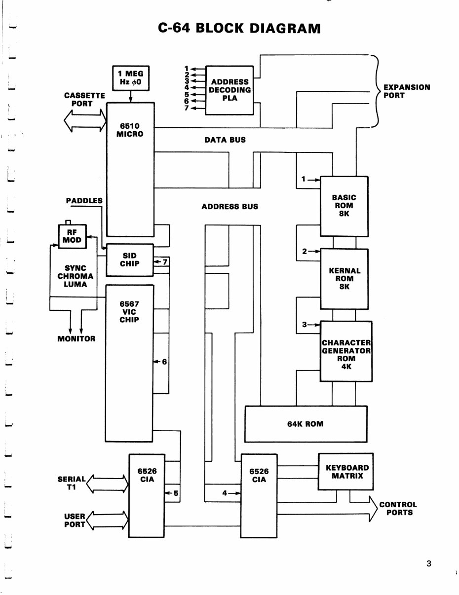
C-64 BLOCK DIAGRAM
CASSETTE
PORT
1 MEG
Hz«AO
\—-V
PADDLES
RF
MOD
SYNC
CHROMA
LUMA
6510
MICRO
SID
CHIP
V V
MONITOR
6567
VIC
CHIP
1
2
3
4-
5-
6-
7-
ADDRESS
DECODING
PLA
J
DATA BUS
ADDRESS BUS
6
EXPANSION
PORT
BASIC
ROM
8K
KERNAL
ROM
8K
CHARACTER
GENERATOR
ROM
4K
64K ROM
USER
PORT
6526
CIA
KEYBOARD
MATRIX
CONTROL
PORTS
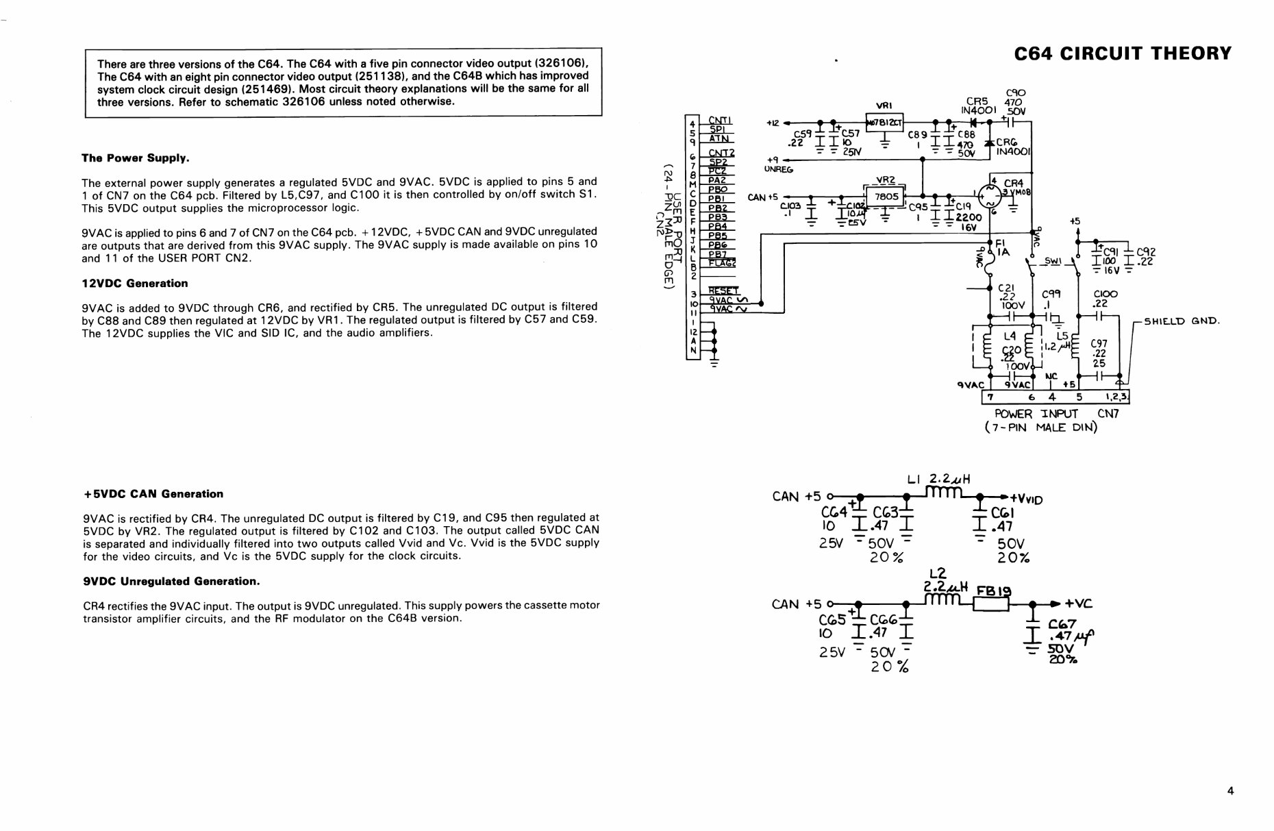
C64 CIRCUIT THEORY
u
+5V
+5V
+SV
R36
IK
<ftESET >
NC
U
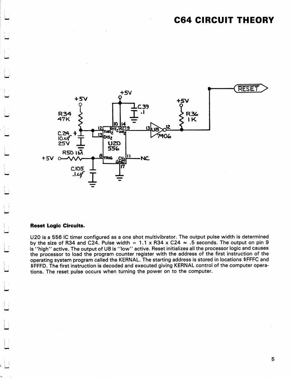
Reset Logic Circuits.
U20 is a 556 IC timer configured as a one shot multivibrator. The output pulse width is determined
by the size of R34 and C24. Pulse width = 1.1 x R34 x C24 » .5 seconds. The output on pin 9
is "high" active. The output of U8 is "low" active. Reset initializes all the processor logic and causes
the processor to load the program counter register with the address of the first instruction of the
operating system program called the KERNAL. The starting address is stored in locations $FFFC and
$FFFD. The first instruction is decoded and executed giving KERNAL control of the computer opera
tions. The reset pulse occurs when turning the power on to the computer.
+Vc
C64 CIRCUIT THEORY
U32 MC4O44
8.1616 MHi
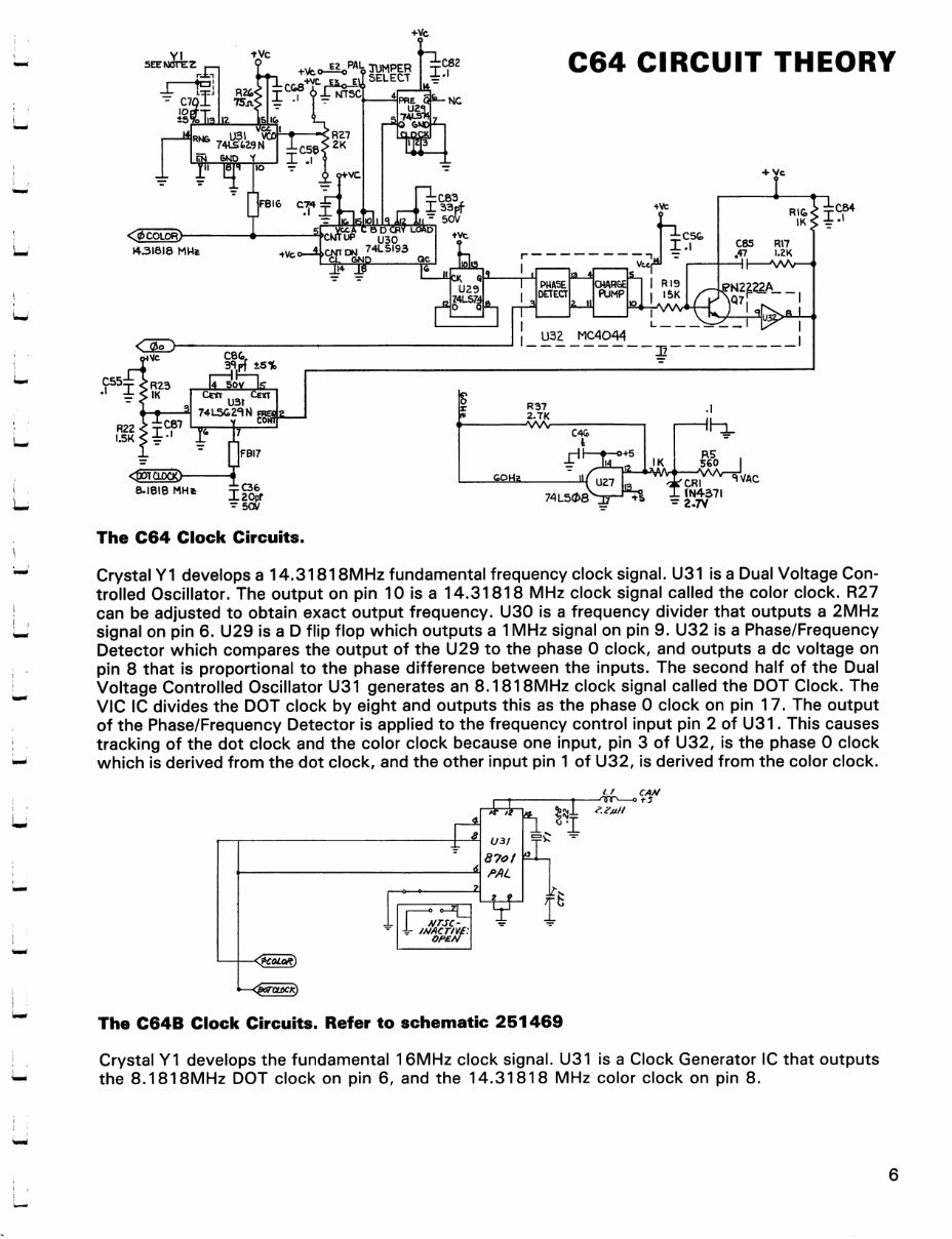
The C64 Clock Circuits.
X (N457I
Crystal Y1 develops a 14.31818MHz fundamental frequency clock signal. U31 is a Dual Voltage Con
trolled Oscillator. The output on pin 10 is a 14.31818 MHz clock signal called the color clock. R27
can be adjusted to obtain exact output frequency. U30 is a frequency divider that outputs a 2MHz
signal on pin 6. U29 is a D flip flop which outputs a 1 MHz signal on pin 9. U32 is a Phase/Frequency
Detector which compares the output of the U29 to the phase 0 clock, and outputs a dc voltage on
pin 8 that is proportional to the phase difference between the inputs. The second half of the Dual
Voltage Controlled Oscillator U31 generates an 8.1818MHz clock signal called the DOT Clock. The
VIC IC divides the DOT clock by eight and outputs this as the phase 0 clock on pin 17. The output
of the Phase/Frequency Detector is applied to the frequency control input pin 2 of U31. This causes
tracking of the dot clock and the color clock because one input, pin 3 of U32, is the phase 0 clock
which is derived from the dot clock, and the other input pin 1 of U32, is derived from the color clock.
I t f TfiP o t-5
u
I
U3/
87ol
PAL
OPEN
T
The C64B Clock Circuits. Refer to schematic 251469
Crystal Y1 develops the fundamental 16MHz clock signal. U31 is a Clock Generator IC that outputs
the 8.1818MHz DOT clock on pin 6, and the 14.31818 MHz color clock on pin 8.
You're Reading a Preview
What's Included?
Fast Download Speeds
Online & Offline Access
Access PDF Contents & Bookmarks
Full Search Facility
Print one or all pages of your manual
$31.99
$41.99
Viewed 50 Times Today


Secure transaction
What's Included?
Fast Download Speeds
Online & Offline Access
Access PDF Contents & Bookmarks
Full Search Facility
Print one or all pages of your manual
$31.99
$41.99
If you are in need of a comprehensive service and repair manual for the rare Commodore C64 or C64C computer, look no further. Our digital manual provides detailed technical information essential for both professional mechanics and DIY enthusiasts. Whether you are troubleshooting hardware issues or seeking to understand the intricacies of the system, this manual is an invaluable resource. It is available in .PDF format, ensuring easy access and compatibility across various devices.


