2 DMC-TZ2GN DMC-TZ2GT Vol. 1 Colour (S)...........Silver Type (K)...........Black Type (except DMC-TZ2PL/GD/GT) (A)...........Blue Type (only DMC-TZ3P/PC/EB/EE/EF/EG/ EGM/GC/SG) TABLE OF CONTENTS PAGE PAGE 1 Safety Precaution ------------------------------------------------- 3 1.1. General Guidelines ----------------------------------------3 1.2. Leakage Current Cold Check ---------------------------3 1.3. Leakage Current Hot Check (See Figure 1.)--------3 1.4. How to Discharge the Capacitor on Flash PCB------------------------------------------------------------4 2 Warning -------------------------------------------------------------- 5 2.1. Prevention of Electrostatic Discharge (ESD) to ElectrostaticallySensitive (ES) Devices -----------5 2.2. How to Recycle the Lithium Ion Battery (U.S. Only)-----------------------------------------------------------5 2.3. Caution for AC Cord(For EB/GC/SG) -----------------6 2.4. How to Replace the Lithium Battery -------------------7 3 Service Navigation------------------------------------------------ 8 3.1. Introduction --------------------------------------------------8 3.2. General Description About Lead Free Solder (PbF) ----------------------------------------------------------8 3.3. Important Notice 1:(Other than U.S.A. and Canadian Market) ------------------------------------------8 3.4. How to Define the Model Suffix (NTSC or PAL model)---------------------------------------------------------9 4 Specifications ---------------------------------------------------- 12 5 Location of Controls and Components ------------------ 13 6 Service Mode ----------------------------------------------------- 15 6.1. Error Code Memory Function ------------------------- 15 6.2. Confirmation of Firmware Version ------------------- 18 7 Service Fixture & Tools --------------------------------------- 19 7.1. Service Fixture and Tools ------------------------------19 7.2. When Replacing the Main PCB ---------------------- 20 7.3. Service Position ------------------------------------------ 20 8 Disassembly and Assembly Instructions --------------- 22 8.1. Disassembly Flow Chart-------------------------------- 22 8.2. PCB Location---------------------------------------------- 22 8.3. Disassembly Procedure -------------------------------- 23 8.4. Disassembly Procedure for the Lens --------------- 28 8.5. Assembly Procedure for the Lens ------------------- 31 8.6. Removal of the CCD Unit ------------------------------ 35 8.7. Removal of the Zoom Motor Unit -------------------- 35 8.8. Removal of the Focus Motor Unit -------------------- 36 8.9. The Applyment of Grease Method------------------- 36 9 Measurements and Adjustments -------------------------- 37 9.1. Matrix Chart for Replaced Part and Necessary Adjustment------------------------------------------------- 37 10 Maintenace -------------------------------------------------------- 38 10.1. Cleaning Lens and LCD Panel ----------------------- 38 Downloaded from www.Manualslib.com manuals search engine
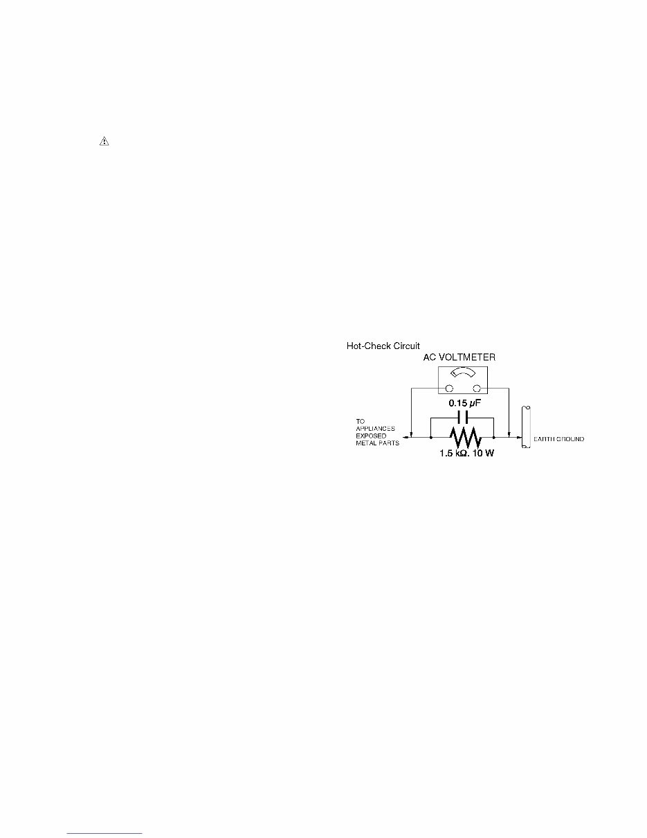
3 1 Safety Precaution 1.1. General Guidelines 1. IMPORTANT SAFETY NOTICE There are special components used in this equipment which are important for safety. These parts are marked by in the Schematic Diagrams, Circuit Board Layout, Exploded Views and Replacement Parts List. It is essen- tial that these critical parts should be replaced with manu- facturer’s specified parts to prevent X-RADIATION, shock, fire, or other hazards. Do not modify the original design without permission of manufacturer. 2. An Isolation Transformer should always be used during the servicing of AC Adaptor whose chassis is not isolated from the AC power line. Use a transformer of adequate power rating as this protects the technician from acci- dents resulting in personal injury from electrical shocks. It will also protect AC Adaptor from being damaged by acci- dental shorting that may occur during servicing. 3. When servicing, observe the original lead dress. If a short circuit is found, replace all parts which have been over- heated or damaged by the short circuit. 4. After servicing, see to it that all the protective devices such as insulation barriers, insulation papers shields are properly installed. 5. After servicing, make the following leakage current checks to prevent the customer from being exposed to shock hazards. 1.2. Leakage Current Cold Check 1. Unplug the AC cord and connect a jumper between the two prongs on the plug. 2. Measure the resistance value, with an ohmmeter, between the jumpered AC plug and each exposed metal- lic cabinet part on the equipment such as screwheads, connectors, control shafts, etc. When the exposed metal- lic part has a return path to the chassis, the reading should be between 1 MΩ and 5.2 MΩ. When the exposed metal does not have a return path to the chassis, the reading must be infinity. 1.3. Leakage Current Hot Check (See Figure 1.) 1. Plug the AC cord directly into the AC outlet. Do not use an isolation transformer for this check. 2. Connect a 1.5 kΩ, 10 W resistor, in parallel with a 0.15 μF capacitor, between each exposed metallic part on the set and a good earth ground, as shown in Figure 1. 3. Use an AC voltmeter, with 1 kΩ/V or more sensitivity, to measure the potential across the resistor. 4. Check each exposed metallic part, and measure the volt- age at each point. 5. Reverse the AC plug in the AC outlet and repeat each of the above measurements. 6. The potential at any point should not exceed 0.75 V RMS. A leakage current tester (Simpson Model 229 or equiva- lent) may be used to make the hot checks, leakage cur- rent must not exceed 1/2 mA. In case a measurement is outside of the limits specified, there is a possibility of a shock hazard, and the equipment should be repaired and rechecked before it is returned to the customer. Figure. 1 Downloaded from www.Manualslib.com manuals search engine
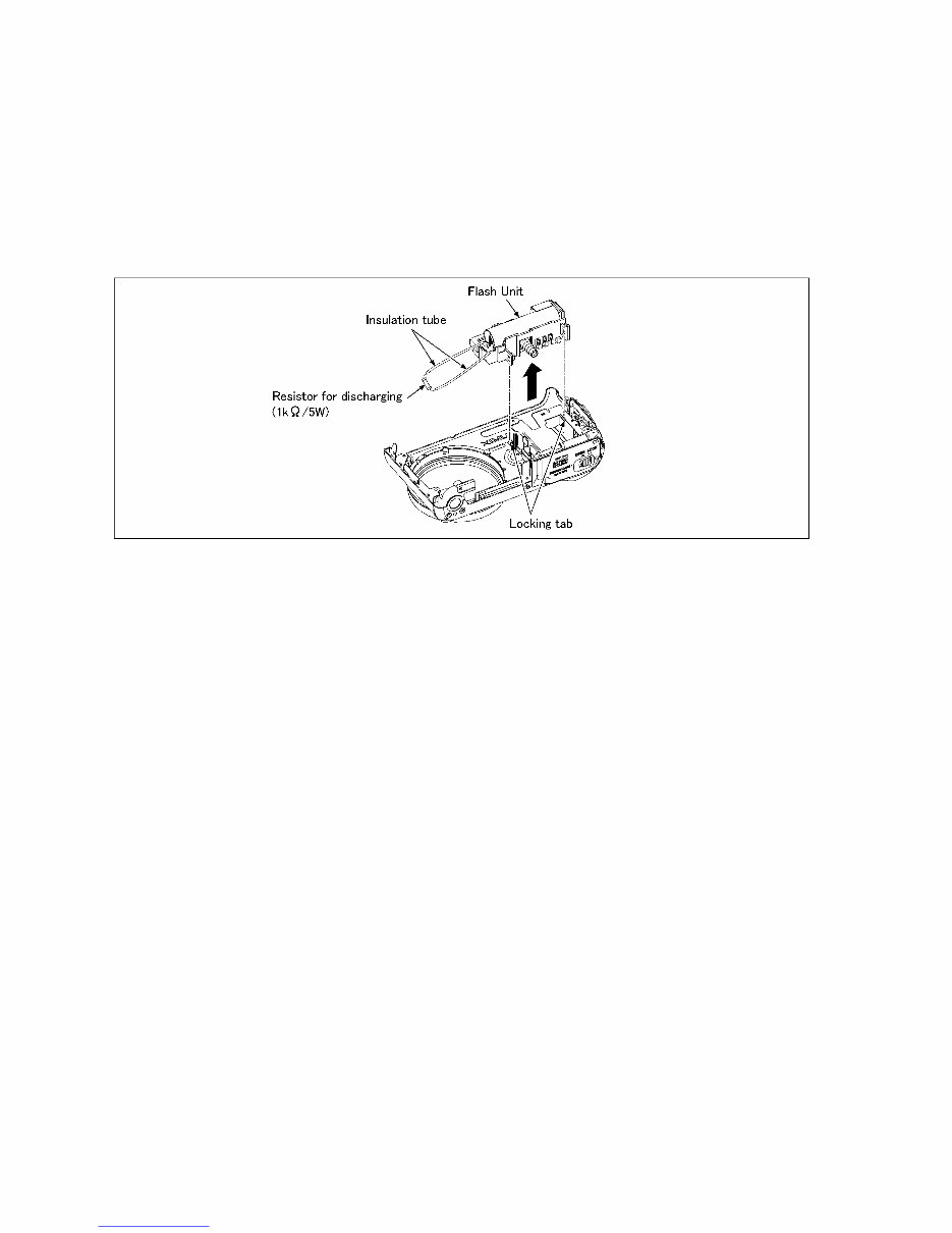
4 1.4. How to Discharge the Capacitor on Flash PCB CAUTION: 1. Be sure to discharge the capacitor on FLASH PCB. 2. Be careful of the high voltage circuit on FLASH PCB when servicing. [Discharging Procedure] 1. Refer to the disassemble procedure and Remove the necessary parts/unit. 2. Put the insulation tube onto the lead part of Resistor (ERG5SJ102:1kΩ /5W). (an equivalent type of resistor may be used.) 3. Put the resistor between both terminals of capacitor on FLASH PCB for approx. 5 seconds. 4. After discharging confirm that the capacitor voltage is lower than 10V using a voltmeter. Fig. F1 Downloaded from www.Manualslib.com manuals search engine
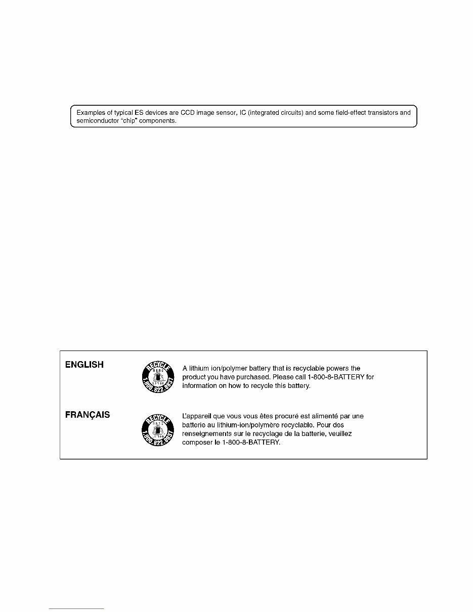
5 2 Warning 2.1. Prevention of Electrostatic Discharge (ESD) to Electrostatically Sensitive (ES) Devices Some semiconductor (solid state) devices can be damaged easily by static electricity. Such components commonly are called Elec- trostatically Sensitive (ES) Devices. The following techniques should be used to help reduce the incidence of component damage caused by electrostatic discharge (ESD). 1. Immediately before handling any semiconductor component or semiconductor-equipped assembly, drain off any ESD on your body by touching a known earth ground. Alternatively, obtain and wear a commercially available discharging ESD wrist strap, which should be removed for potential shock reasons prior to applying power to the unit under test. 2. After removing an electrical assembly equipped with ES devices, place the assembly on a conductive surface such as alumi- num foil, to prevent electrostatic charge buildup or exposure of the assembly. 3. Use only a grounded-tip soldering iron to solder or unsolder ES devices. 4. Use only an antistatic solder removal device. Some solder removal devices not classified as "antistatic (ESD protected)" can generate electrical charge sufficient to damage ES devices. 5. Do not use freon-propelled chemicals. These can generate electrical charges sufficient to damage ES devices. 6. Do not remove a replacement ES device from its protective package until immediately before you are ready to install it. (Most replacement ES devices are packaged with leads electrically shorted together by conductive foam, aluminum foil or compara- ble conductive material). 7. Immediately before removing the protective material from the leads of a replacement ES device, touch the protective material to the chassis or circuit assembly into which the device will be installed. CAUTION : Be sure no power is applied to the chassis or circuit, and observe all other safety precautions. 8. Minimize bodily motions when handling unpackaged replacement ES devices. (Otherwise harmless motion such as the brushing together of your clothes fabric or the lifting of your foot from a carpeted floor can generate static electricity (ESD) suf- ficient to damage an ES device). 2.2. How to Recycle the Lithium Ion Battery (U.S. Only) Downloaded from www.Manualslib.com manuals search engine
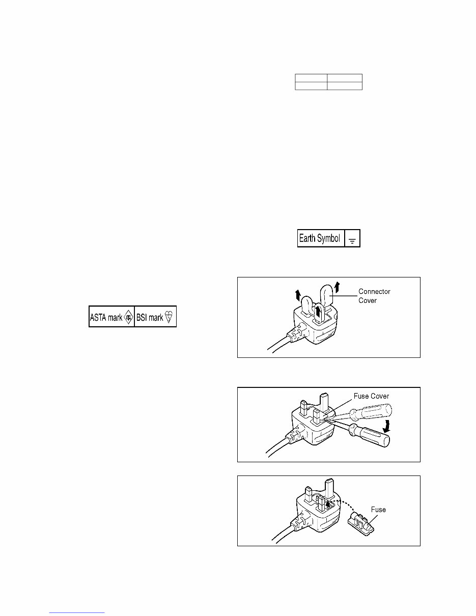
6 2.3. Caution for AC Cord (For EB/GC/SG) 2.3.1. Information for Your Safety IMPORTANT Your attention is drawn to the fact that recording of pre- recorded tapes or discs or other published or broadcast material may infringe copyright laws. WARNING To reduce the risk of fire or shock hazard, do not expose this equipment to rain or moisture. CAUTION To reduce the risk of fire or shock hazard and annoying interference, use the recommended accessories only. FOR YOUR SAFETY DO NOT REMOVE THE OUTER COVER To prevent electric shock, do not remove the cover. No user serviceable parts inside. Refer servicing to qualified service personnel. 2.3.2. Caution for AC Mains Lead For your safety, please read the following text carefully. This appliance is supplied with a moulded three-pin mains plug for your safety and convenience. A 5-ampere fuse is fitted in this plug. Should the fuse need to be replaced please ensure that the replacement fuse has a rating of 5 amperes and it is approved by ASTA or BSI to BS1362 Check for the ASRA mark or the BSI mark on the body of the fuse. If the plug contains a removable fuse cover you must ensure that it is refitted when the fuse is replaced. If you lose the fuse cover, the plug must not be used until a replacement cover is obtained. A replacement fuse cover can be purchased from your local Panasonic Dealer. If the fitted moulded plug is unsuitable for the socket outlet in your home then the fuse should be removed and the plug cut off and disposed of safety. There is a danger of severe electrical shock if the cut off plug is inserted into any 13-ampere socket. If a new plug is to be fitted please observe the wiring code as shown below. If in any doubt, please consult a qualified electrician. 2.3.2.1. Important The wires in this mains lead are coloured in accordance with the following code: As the colours of the wires in the mains lead of this appliance may not correspond with the coloured markings identifying the terminals in your plug, proceed as follows: The wire which is coloured BLUE must be connected to the ter- minal in the plug which is marked with the letter N or coloured BLACK. The wire which is coloured BROWN must be connected to the terminal in the plug which is marked with the letter L or coloured RED. Under no circumstances should either of these wires be con- nected to the earth terminal of the three pin plug, marked with the letter E or the Earth Symbol. 2.3.2.2. Before Use Remove the Connector Cover as follows. 2.3.2.3. How to Replace the Fuse 1. Remove the Fuse Cover with a screwdriver. 2. Replace the fuse and attach the Fuse cover. Blue Neutral Brown Live Downloaded from www.Manualslib.com manuals search engine
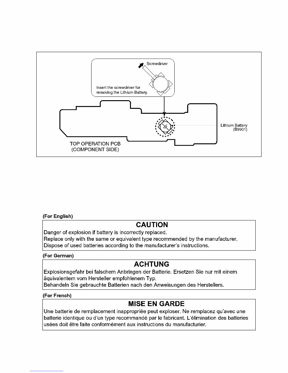
7 2.4. How to Replace the Lithium Battery 2.4.1. Replacement Procedure 1. Remove the Top Operation PCB. (Refer to Disassembly Procedures.) 2. Remove the Lithium battery (Ref. No. “B9901” at component side of Top Operation PCB) and then replace it into new one. NOTE: This Lithium battery is a critical component. (Type No.: ML614S/ZT Manufactured by Matsushita Battery Industrial Co.,Ltd.) It must never be subjected to excessive heat or discharge. It must therefore only be fitted in requirement designed specifically for its use. Replacement batteries must be of same type and manufacture. They must be fitted in the same manner and location as the original battery, with the correct polarity contacts observed. Do not attempt to re-charge the old battery or re-use it for any other purpose. It should be disposed of in waste products destined for burial rather than incineration. NOTE: Above caution is applicable for a battery pack which is for DMC-TZ3/TZ2 series, as well. Downloaded from www.Manualslib.com manuals search engine
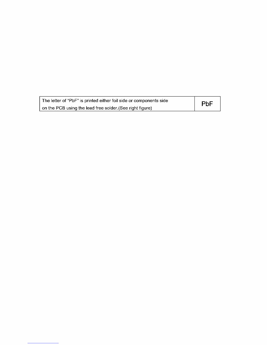
8 3 Service Navigation 3.1. Introduction This service manual contains technical information, which allow service personnel’s to understand and service this model. Please place orders using the parts list and not the drawing reference numbers. If the circuit is changed or modified, the information will be followed by service manual to be controlled with original service manual. 3.2. General Description About Lead Free Solder (PbF) The lead free solder has been used in the mounting process of all electrical components on the printed circuit boards used for this equipment in considering the globally environmental conservation. The normal solder is the alloy of tin (Sn) and lead (Pb). On the other hand, the lead free solder is the alloy mainly consists of tin (Sn), silver (Ag) and Copper (Cu), and the melting point of the lead free solder is higher approx.30°C (86°F) more than that of the normal solder. Distinction of PCB Lead Free Solder being used Service caution for repair work using Lead Free Solder (PbF) • The lead free solder has to be used when repairing the equipment for which the lead free solder is used. (Definition: The letter of “PbF” is printed on the PCB using the lead free solder.) • To put lead free solder, it should be well molten and mixed with the original lead free solder. • Remove the remaining lead free solder on the PCB cleanly for soldering of the new IC. • Since the melting point of the lead free solder is higher than that of the normal lead solder, it takes the longer time to melt the lead free solder. • Use the soldering iron (more than 70W) equipped with the temperature control after setting the temperature at 350±30°C (662±86°F). Recommended Lead Free Solder (Service Parts Route.) • The following 3 types of lead free solder are available through the service parts route. RFKZ03D01K-----------(0.3mm 100g Reel) RFKZ06D01K-----------(0.6mm 100g Reel) RFKZ10D01K-----------(1.0mm 100g Reel) Note * Ingredient: tin (Sn) 96.5%, silver (Ag) 3.0%, Copper (Cu) 0.5%, Cobalt (Co) / Germanium (Ge) 0.1 to 0.3% 3.3. Important Notice 1:(Other than U.S.A. and Canadian Market) 1. The service manual does not contain the following information, because of the impossibility of servicing at component level without concerned equipment/facilites. a. Schematic diagram, Block Diagram and PCB layout of MAIN PCB. b. Parts list for individual parts for MAIN PCB. When a part replacement is required for repairing MAIN PCB, replace as an assembled parts. (Main PCB) 2. The following category is/are recycle module part. please send it/them to Central Repair Center. • MAIN PCB (TZ3: VEP56047A/TZ2: VEP56047B) Downloaded from www.Manualslib.com manuals search engine
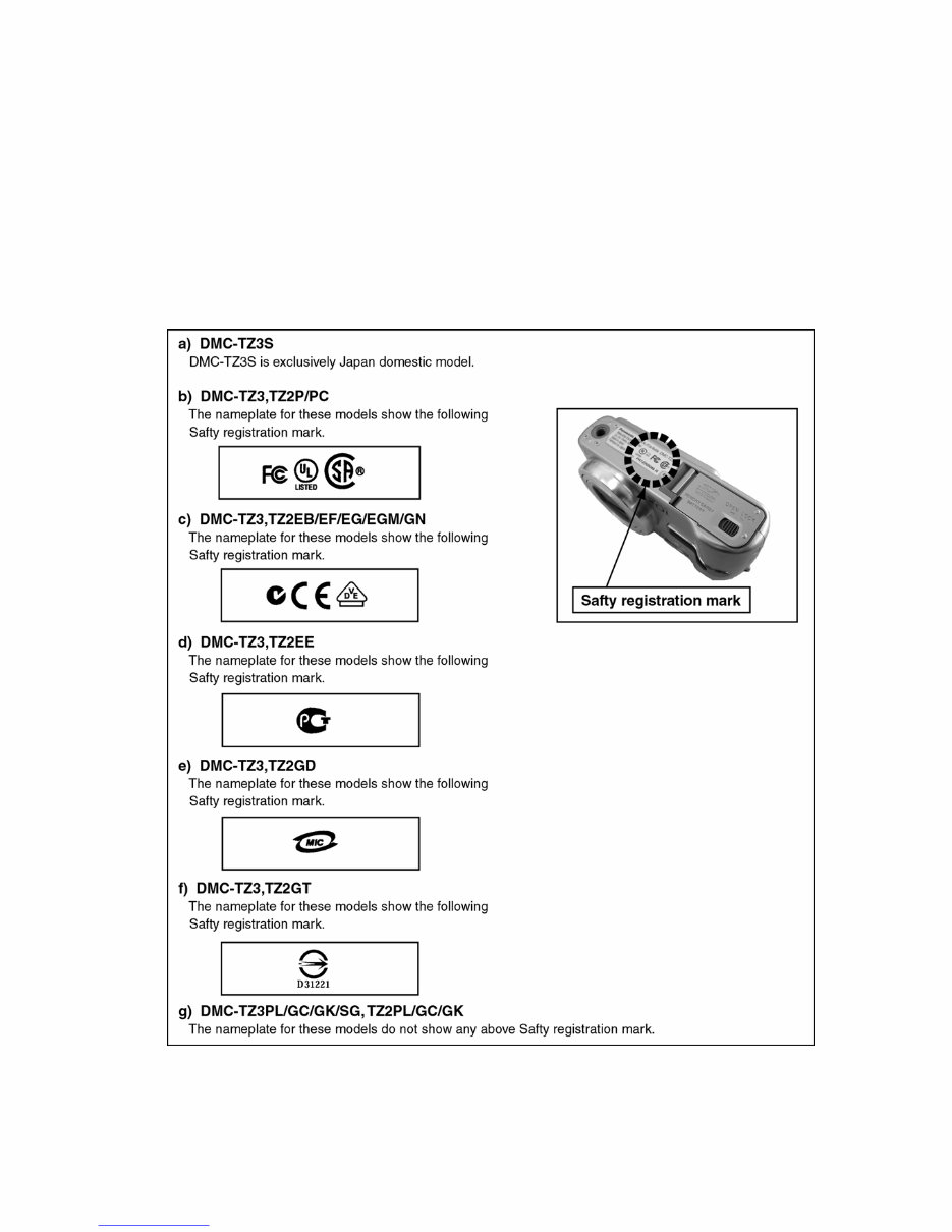
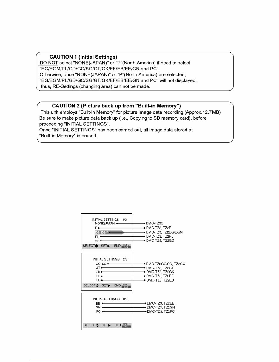
9 3.4. How to Define the Model Suffix (NTSC or PAL model) There are seven kinds of DMC-TZ3/TZ2, regardless of the colours. • a) DMC-TZ3S • b) DMC-TZ3, TZ2P/PC • c) DMC-TZ3, TZ2EB/EF/EG/EGM/GN • d) DMC-TZ3, TZ2EE • e) DMC-TZ3, TZ2GD • f) DMC-TZ3, TZ2GT • g) DMC-TZ3PL/GC/GK/SG, TZ2PL/GC/GK (DMC-TZ3S is exclusively Japan domestic model.) What is the difference is that the “INITIAL SETTINGS” data which is stored in Flash ROM mounted on Main PCB. 3.4.1. Defining methods: To define the model suffix to be serviced, refer to the nameplate which is putted on the bottom side of the Unit. NOTE: After replacing the MAIN PCB, be sure to achieve adjustment. The adjustment instruction is available at “software download” on the “Support Information from NWBG/VDBG-PAVC” web-site in “TSN system”, together with Maintenance software. Downloaded from www.Manualslib.com manuals search engine
10 3.4.2. INITIAL SETTINGS: When you replace the Main PCB, be sure to perform the initial settings after achieving the adjustment by ordering the following pro- cedure in accordance with model suffix of the unit. 1. IMPORTANT NOTICE: Before proceeding Initial settings, be sure to read the following CAUTIONS. 2. PROCEDURES: • Preparation. Proceed the picture back up from the unit (Refer to above "CAUTION 2") • Step 1. The temporary cancellation of factory setting: Set the mode dial to “[ Normal picture mode ] (Red camera mark)”. While keep pressing [ Optical Image Stabilizer ] and “[ UP ] of Cross key” simultaneously, turn the Power on. • Step 2. The cancellation of factory setting: Set the mode dial to “[ Playback ]”. Press [ Optical Image Stabilizer ] and “[ UP ] of Cross key” simultaneously, then turn the Power off. • Step 3. Turn the Power on: Set the mode dial to “[ Normal picture mode ] (Red camera mark)”, and then turn the Power on. • Step 4. Display the INITIAL SETTING: While keep pressing [ MENU ] and “[ RIGHT ] of Cross key” simultaneously, turn the Power off. Downloaded from www.Manualslib.com manuals search engine
Are you experiencing issues with your Panasonic DMC-TZ3/TZ2 Camera? Instead of spending a significant amount on repairs or replacements, why not take matters into your own hands?
This comprehensive service and repair manual is utilized by the Official Certified Panasonic Technicians and is designed to assist you in troubleshooting and fixing your Camera!
Contents:
Safety Precaution
General Guidelines
Leakage Current Cold Check
Leakage Current Hot Check (See Figure 1.)
How to Discharge the Capacitor on Flash PCB
Warning
Prevention of Electrostatic Discharge (ES to Electro statically Sensitive (ES) Devices
How to Recycle the Lithium Ion Battery
Caution for AC Cord(For EB/GC/SG)
How to Replace the Lithium Battery
Service Navigation
Introduction
General Description About Lead Free Solder
Important Notice
How to Define the Model Suffix
Specifications
Location of Controls and Components
Service Mode
Error Code Memory Function
Confirmation of Firmware Version
Service Fixture & Tools
Service Fixture and Tools
When Replacing the Main PCB
Service Position
Disassembly and Assembly Instructions
Disassembly Flow Chart
PCB Location
Disassembly Procedure
Disassembly Procedure for the Lens
Assembly Procedure for the Lens
Removal of the CCD Unit
Removal of the Zoom Motor Unit
Removal of the Focus Motor Unit
The Application of Grease Method
Measurements and Adjustments
Matrix Chart for Replaced Part and Necessary Adjustment
Maintenance
Cleaning Lens and LCD Panel
This manual covers various models including DMC-TZ3P, DMC-TZ3PC, DMC-TZ3PL, DMC-TZ3EB, DMC-TZ3EE, DMC-TZ3EF, DMC-TZ3EG, DMC-TZ3EGM, DMC-TZ3GC, DMC-TZ3GD, DMC-TZ3GK, DMC-TZ3GN, DMC-TZ3GT, DMC-TZ3SG, DMC-TZ2P, DMC-TZ2PC, DMC-TZ2PL, DMC-TZ2EB, DMC-TZ2EE, DMC-TZ2EF, DMC-TZ2EG, DMC-TZ2EGM, DMC-TZ2GC, DMC-TZ2GD, and DMC-TZ2GK.
This detailed service manual includes colored pictures and step-by-step instructions to effectively repair/service your device. It is the OFFICIAL service and repair manual in PDF format, ensuring high-resolution quality for printing.
Gain instant access to this valuable resource after payment, eliminating shipping fees and waiting time. The manual is compatible with Windows and MAC platforms.
If you are unable to find a specific service manual, feel free to reach out to us with your request. With one of the largest service manual databases, we are well-equipped to assist you!
Specifications:
Language: English
Format: PDF
Pages: 60
Platform: Windows and MAC
Recently Viewed
5,521,897Happy Clients
2,594,462eManuals
1,120,453Trusted Sellers
15Years in Business
Price:
Actual Price:
Panasonic Lumix DMC-TZ3 + TZ2 Service Manual & Repair Guide