— 2 — DCR-HC23E/HC24E/HC26/HC26E/HC35E_L2 SPECIFICATIONS These specifications are extracted from instruction manual ofDCR-HC23E/HC24E/HC26E/HC35E. System Video recording system 2 rotary heads, Helical scanning system Audio recording system Rotary heads, PCM system Quantization: 12 bits (Fs 32 kHz, stereo 1, stereo 2), 16 bits (Fs 48 kHz, stereo) Video signal PAL color, CCIR standards Usable cassette Mini DV cassette with the mark printed Tape speed SP: Approx. 18.81 mm/s LP: Approx. 12.56 mm/s Recording/playback time SP: 60 min (using a DVM60 cassette) LP: 90 min (using a DVM60 cassette) Fast forward/rewind time Approx. 2 min 40 s (using a DVM60 cassette and rechargeable battery pack) Approx. 1 min 45 s (using a DVM60 cassette and AC Adaptor) Viewfinder Electric viewfinder (color) Image device 3.0 mm (1/6 type) CCD (Charge Coupled Device) Gross: Approx. 800 000 pixels Effective (movie): Approx. 400 000 pixels Lens DCR-HC23E: Carl Zeiss Vario-Tessar 20 × (Optical), 640 × (Digital) DCR-HC24E/HC26E/HC35E: Carl Zeiss Vario-Tessar 20 × (Optical), 800 × (Digital) Focal length f=2.3 ~ 46 mm (3/32 ~ 1 13/16 in.) When converted to a 35 mm still camera In CAMERA: 44 ~ 880 mm (1 3/4 ~ 34 1/32 in.) F1.8 ~ 3.1 Filter diameter: 25 mm (1 in.) Color temperature [AUTO], [ONE PUSH], [INDOOR] (3 200 K), [OUTDOOR] (5 800 K) Minimum illumination 5 lx (lux) (F 1.8) 0 lx (lux) (during NightShot plus function)* 1 * 1 Objects unable to be seen due to the dark can be shot with infrared lighting. Input/Output connectors Audio/Video output 10-pin connector Video signal: 1 Vp-p, 75 Ω (ohms), unbalanced Luminance signal: 1 Vp-p, 75 Ω (ohms), unbalanced Chrominance signal: 0.3 Vp-p, 75 Ω (ohms), unbalanced Audio signal: 327 mV (at load impedance 47 kΩ (kilohms)), Output impedance with less than 2.2 kΩ (kilohms) USB jack (DCR-HC23E/HC24E/HC26E) mini-B DV input/output (DCR-HC26E) i.LINK Interface (IEEE1394, 4-pin connector S100) DV output (DCR-HC23E/HC24E) i.LINK Interface (IEEE1394, 4-pin connector S100) LCD screen Picture 6.2 cm (2.5 type) Total dot number 123 200 (560 × 220) General Power requirements DC 7.2 V (battery pack) DC 8.4 V (AC Adaptor) Average power consumption During camera recording using the viewfinder 1.8 W During camera recording using the LCD 2.1 W Operating temperature 0 °C to 40 °C (32 °F to 104 °F) Storage temperature -20 °C to + 60 °C (-4 °F to + 140 °F) Dimensions (approx.) 65 × 79 × 113 mm (2 5/8 × 3 1/8 × 4 1/2 in.) (w/h/d) Mass (approx.) DCR-HC23E/HC24E/HC26E: 360 g (12 oz) main unit only 420 g (14 oz) including the NP-FP30 rechargeable battery pack and DVM60 cassette. DCR-HC35E: 370 g (13 oz) main unit only 430 g (15 oz) including the NP-FP30 rechargeable battery pack and DVM60 cassette. Audio signal: 327 mV (at load impedance 47 kΩ (kilohms)), Output impedance with less than 2.2 kΩ (kilohms) USB jack mini-B DV input/output i.LINK Interface (IEEE1394, 4-pin connector S100) AC Adaptor AC-L25A/L25B Power requirements AC 100 - 240 V, 50/60 Hz Current consumption 0.35 - 0.18 A Power consumption 18 W Output voltage DC 8.4 V* 2 Operating temperature 0 °C to 40 °C (32 °F to 104 °F) Storage temperature -20 °C to + 60 °C (-4 °F to + 140 °F) Dimensions (approx.) 56 × 31 × 100 mm (2 1/4 × 1 1/4 × 4 in.) (w/h/d) excluding the projecting parts Mass (approx.) 190 g (6.7 oz) excluding the mains lead * 2 See the label on the AC Adaptor for other specifications. Rechargeable battery pack (NP-FP30) Maximum output voltage DC 8.4 V Output voltage DC 7.2 V Capacity 3.6 Wh (500 mAh) Dimensions (approx.) 31.8 × 18.5 × 45.0 mm (1 5/16 × 3/4 × 1 13/16 in) (w/h/d) Mass (approx.) 40 g (1.5 oz) Operating temperature 0 °C to 40 °C (32 °F to 104 °F) Type Lithium ion Design and specifications are subject to change without notice. Supplied accessories See page 6. AC Adaptor (1) Mains lead (1) Handycam Station (1) (DCR-HC35E) Wireless Remote Commander (1) (DCR-HC24E/HC35E) A/V connecting cable (1) USB cable (1) (DCR-HC24E/HC35E) Lens cap (1) Rechargeable battery pack NP-FP30 (1) CD-ROM “Picture Package Ver.1.5.1” (1) 21-pin adaptor (1) (DCR-HC35E) Operating Guide (1) Handycam Station DCRA-C151 Input/Output connectors (DCR-HC35E) Audio/Video output 10- pin connector Video signal: 1 Vp-p, 75 Ω (ohms), unbalanced Luminance signal: 1 Vp-p, 75 Ω (ohms) , unbalanced Chrominance signal : 0.3 Vp-p, 75 Ω (ohms) , unbalanced
— 3 — DCR-HC23E/HC24E/HC26/HC26E/HC35E_L2 Model DCR-HC23E DCR-HC24E DCR-HC26 DCR-HC26E DCR-HC35E Destination AEP, EE, NE AEP, UK, EE, NE US, CND, E, AR NE, E, AUS, CH, AEP, UK, EE, NE BR, KR HK Color system PAL PAL NTSC PAL PAL DV Interface OUT OUT IN/OUT IN/OUT IN/OUT (Note) Remote commander × a × × a Cradle (Handycam Station) × × × × a CR board × × × × CR-061 Model information table • Abbreviation AR : Argentine model AUS : Australian model BR : Brazilian model CH : Chinese model CND : Canadian model EE : East European model HK : Hong Kong model J : Japanese model JE : Tourist model KR : Korea model NE : North European model Note: DV Interface on the Cradle (Handycam Station)
— 4 — DCR-HC23E/HC24E/HC26/HC26E/HC35E_L2 SAFETY-RELATED COMPONENT WARNING!! COMPONENTS IDENTIFIED BY MARK 0 OR DOTTED LINE WITH MARK 0 ON THE SCHEMATIC DIAGRAMS AND IN THE PARTS LIST ARE CRITICAL TO SAFE OPERATION. REPLACE THESE COMPONENTS WITH SONY PARTS WHOSE PART NUMBERS APPEAR AS SHOWN IN THIS MANUAL OR IN SUPPLEMENTS PUBLISHED BY SONY. 1. Check the area of your repair for unsoldered or poorly-soldered connections. Check the entire board surface for solder splashes and bridges. 2. Check the interboard wiring to ensure that no wires are "pinched" or contact high-wattage resistors. 3. Look for unauthorized replacement parts, particularly transistors, that were installed during a previous repair. Point them out to the customer and recommend their replacement. 4. Look for parts which, through functioning, show obvious signs of deterioration. Point them out to the customer and recommend their replacement. 5. Check the B+ voltage to see it is at the values specified. 6. Flexible Circuit Board Repairing • Keep the temperature of the soldering iron around 270˚C during repairing. • Do not touch the soldering iron on the same conductor of the circuit board (within 3 times). • Be careful not to apply force on the conductor when soldering or unsoldering. SAFETY CHECK-OUT After correcting the original service problem, perform the following safety checks before releasing the set to the customer. CAUTION Danger of explosion if battery is incorrectly replaced. Replace only with the same or equivalent type. ATTENTION AU COMPOSANT AYANT RAPPORT À LA SÉCURITÉ! LES COMPOSANTS IDENTIFÉS PAR UNE MARQUE 0 SUR LES DIAGRAMMES SCHÉMATIQUES ET LA LISTE DES PIÈCES SONT CRITIQUES POUR LA SÉCURITÉ DE FONCTIONNEMENT. NE REMPLACER CES COMPOSANTS QUE PAR DES PIÈSES SONY DONT LES NUMÉROS SONT DONNÉS DANS CE MANUEL OU DANS LES SUPPÉMENTS PUBLIÉS PAR SONY. Unleaded solder Boards requiring use of unleaded solder are printed with the lead- free mark (LF) indicating the solder contains no lead. (Caution: Some printed circuit boards may not come printed with the lead free mark due to their particular size.) : LEAD FREE MARK Unleaded solder has the following characteristics. • Unleaded solder melts at a temperature about 40°C higher than ordinary solder. Ordinary soldering irons can be used but the iron tip has to be applied to the solder joint for a slightly longer time. Soldering irons using a temperature regulator should be set to about 350°C. Caution: The printed pattern (copper foil) may peel away if the heated tip is applied for too long, so be careful! • Strong viscosity Unleaded solder is more viscous (sticky, less prone to flow) than ordinary solder so use caution not to let solder bridges occur such as on IC pins, etc. • Usable with ordinary solder It is best to use only unleaded solder but unleaded solder may also be added to ordinary solder.
— 5 — DCR-HC23E/HC24E/HC26/HC26E/HC35E_L2 TABLE OF CONTENTS 1. SERVICE NOTE 1-1. Power Supply During Repairs ········································· 1-1 1-2. To Take Out a Cassette when not Eject (Force Eject) ·····1-1 1-3. Setting the “Forced Power On” Mode ····························· 1-1 1-4. Using Service Jig ····························································· 1-2 1-5. Self-diagnosis Function ··················································· 1-2 1-6. Precaution on Replacing the VC-416 Board ··················· 1-4 2. DISASSEMBLY 2-1. Disassembly ····································································· 2-2 3. BLOCK DIAGRAMS 3-1. Overall Block Diagram (1/5) ··········································· 3-1 3-2. Overall Block Diagram (2/5) ··········································· 3-2 3-3. Overall Block Diagram (3/5) ··········································· 3-3 3-4. Overall Block Diagram (4/5) ··········································· 3-4 3-5. Overall Block Diagram (5/5) ··········································· 3-5 3-6. Power Block Diagram (1/3) ············································· 3-6 3-7. Power Block Diagram (2/3) ············································· 3-7 3-8. Power Block Diagram (3/3) ············································· 3-8 4. PRINTED WIRING BOARDS AND SCHEMATIC DIAGRAMS 4-1. Frame Schematic Diagrams ············································· 4-1 4-2. Schematic Diagrams ························································ 4-3 4-3. Printed Wiring Boards ··················································· 4-25 4-4. Mounted Parts Location ················································ 4-37 5. REPAIR PARTS LIST 5-1. Exploded Views ·······························································5-2 5-2. Electrical Parts List ······················································· 5-12 Section Title P age
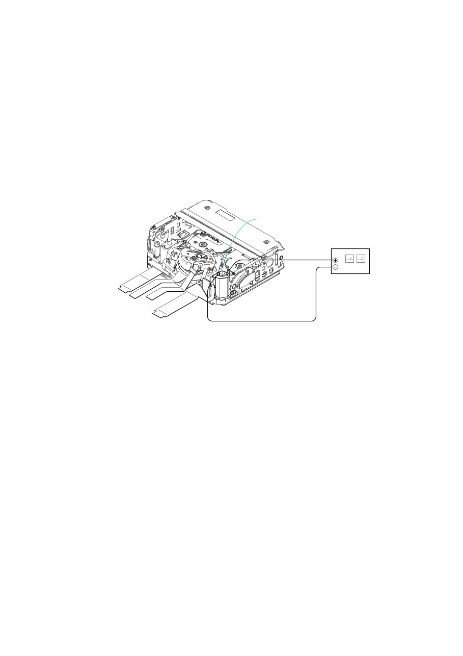
1-1 DCR-HC23E/HC24E/HC26/HC26E/HC35E_L2 1. SERVICE NOTE 1-1. POWER SUPPLY DURING REPAIRS In this unit, about 10 seconds after power is supplied to the battery terminal using the regulated power supply (8.4V), the power is shut off so that the unit cannot operate. These following method is available to prevent this. Method: Use the AC power adaptor (AC-L25A/L25B). 1-2. TO TAKE OUT A CASSETTE WHEN NOT EJECT (FORCE EJECT) 1 Refer to “2. DISASSEMBLY” to remove the mechanism deck block. 2 Supply +4.5V from the DC power supply to the loading motor and unload with a pressing the cassette compartment. Loading motor DC power supply (+ 4.5Vdc) 1-3. SETTING THE “FORCED POWER ON” MODE It is possible to turn on power by adjustment remote commander (RM-95 or NEW LANC JIG). Operate the VTR function using the adjustment remote commander. 1-3-1. Setting the “Forced Camera Power ON” Mode 1) Select page: 0, address: 01, and set data:01. 2) Select page: D, address: 10, set data:01 and press the “PAUSE (Write)” button of the adjustment remote commander. 1-3-2. Setting the “Forced VTR Power ON” Mode 1) Select page: 0, address: 01, and set data:01. 2) Select page: D, address: 10, set data:02 and press the “PAUSE (Write)” button of the adjustment remote commander. 1-3-3. Exiting the “Forced Power ON” Mode 1) Select page: 0, address: 01, and set data:01. 2) Select page: D, address: 10, set data:00 and press the “PAUSE (Write)” button of the adjustment remote commander. 3) Select page: 0, address: 01, and set data: 00.
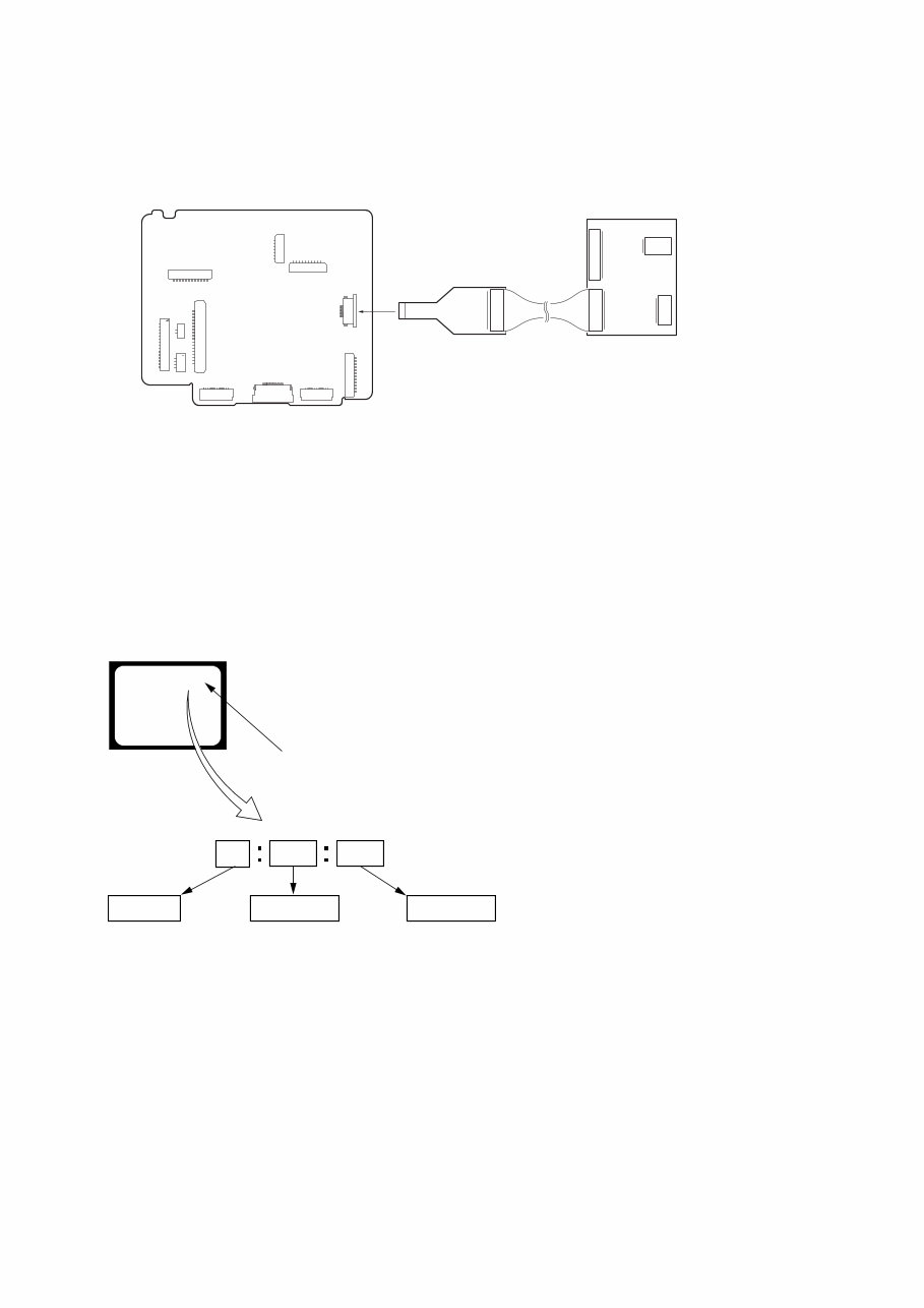
1-2 DCR-HC23E/HC24E/HC26/HC26E/HC35E_L2 1-5. SELF-DIAGNOSIS FUNCTION 1-5-1. Self-diagnosis Function When problems occur while the unit is operating, the self-diagnosis function starts working, and displays on the viewfinder or LCD screen what to do. This function consists of two display; self- diagnosis display and service mode display. Details of the self-diagnosis functions are provided in the Instruction manual. 1-5-2. Self-diagnosis Display When problems occur while the unit is operating, the counter of the viewfinder or LCD screen shows a 4-digit display consisting of an alphabet and numbers, which blinks at 3.2 Hz. This 5-character display indicates the “repaired by:”, “block” in which the problem occurred, and “detailed code” of the problem. 1 1 3 1 C Repaired by: Refer to “1-5-3. Self-diagnosis Code Table”. Indicates the appropriate step to be taken. E.g. 31 ....Reload the tape. 32 ....Turn on power again. Block Detailed Code Blinks at 3.2Hz C : Corrected by customer H : Corrected by dealer E : Corrected by service engineer Viewfinder or LCD screen C : 3 1 : 1 1 1 8 CN1014 VC-416 BOARD (SIDE A) CPC-15 (J-6082-564-A) I/F unit for LANC control (J-6082-521-A) 1-4. USING SERVICE JIG Connect the CPC-15 jig connector (J-6082-564-A) and I/F unit for LANC conrol (J-6082-521-A) to the CN1014 of VC-416 board.
1-3 DCR-HC23E/HC24E/HC26/HC26E/HC35E_L2 1-5-3. Self-diagnosis Code Table C C C C C C C C C C C C C C C C C C C C C C C C C C C C C Block Function 0 4 2 1 2 2 3 1 3 1 3 1 3 1 3 1 3 1 3 1 3 1 3 1 3 1 3 1 3 1 3 1 3 2 3 2 3 2 3 2 3 2 3 2 3 2 3 2 3 2 3 2 3 2 3 2 3 2 Detailed Code 0 0 0 0 0 0 1 0 1 1 2 0 2 1 2 2 2 3 3 0 3 1 4 0 4 1 4 2 4 3 4 4 1 0 1 1 2 0 2 1 2 2 2 3 3 0 3 1 4 0 4 1 4 2 4 3 4 4 Symptom/State Non-standard battery is used. Condensation. Video head is dirty. LOAD direction. Loading does not complete within specified time UNLOAD direction. Loading does not complete within specified time T reel side tape slacking when unloading. S reel side tape slacking when unloading. T reel fault. S reel fault. FG fault when starting capstan. FG fault during normal capstan operations. FG fault when starting drum. PG fault when starting drum. FG fault during normal drum operations. PG fault during normal drum operations. Phase fault during normal drum operations. LOAD direction loading motor time- out. UNLOAD direction loading motor time-out. T reel side tape slacking when unloading. S reel side tape slacking when unloading. T reel fault. S reel fault. FG fault when starting capstan. FG fault during normal capstan operations. FG fault when starting drum. PG fault when starting drum. FG fault during normal drum operations. PG fault during normal drum operations. Phase fault during normal drum operations. Self-diagnosis Code Repaired by: Correction Use the InfoLITHIUM battery. Remove the cassette, and insert it again after one hour. Clean with the optional cleaning cassette. Load the tape again, and perform operations from the beginning. Load the tape again, and perform operations from the beginning. Load the tape again, and perform operations from the beginning. Load the tape again, and perform operations from the beginning. Load the tape again, and perform operations from the beginning. Load the tape again, and perform operations from the beginning. Load the tape again, and perform operations from the beginning. Load the tape again, and perform operations from the beginning. Load the tape again, and perform operations from the beginning. Load the tape again, and perform operations from the beginning. Load the tape again, and perform operations from the beginning. Load the tape again, and perform operations from the beginning. Load the tape again, and perform operations from the beginning. Remove the battery or power cable, connect, and perform operations from the beginning. Remove the battery or power cable, connect, and perform operations from the beginning. Remove the battery or power cable, connect, and perform operations from the beginning. Remove the battery or power cable, connect, and perform operations from the beginning. Remove the battery or power cable, connect, and perform operations from the beginning. Remove the battery or power cable, connect, and perform operations from the beginning. Remove the battery or power cable, connect, and perform operations from the beginning. Remove the battery or power cable, connect, and perform operations from the beginning. Remove the battery or power cable, connect, and perform operations from the beginning. Remove the battery or power cable, connect, and perform operations from the beginning. Remove the battery or power cable, connect, and perform operations from the beginning. Remove the battery or power cable, connect, and perform operations from the beginning. Remove the battery or power cable, connect, and perform operations from the beginning.
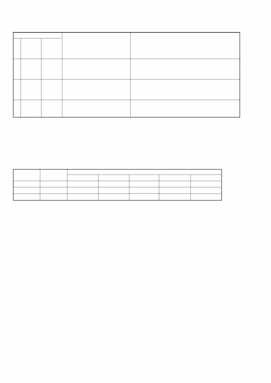
1-4E DCR-HC23E/HC24E/HC26/HC26E/HC35E_L2 E E E Block Function 6 1 6 1 6 1 Detailed Code 0 0 1 0 1 1 Symptom/State Difficult to adjust focus (Cannot initialize focus.) Zoom operations fault (Cannot initialize zoom lens.) Focus lens initializing failure and zoom lens initializing failure occur simulta- neously. Self-diagnosis Code Repaired by: Correction Inspect the lens block focus reset sensor (Pin ql, of CN3101 of VC- 416 board) when focusing is performed when the touch panel is operated in the focus manual mode and the focus motor drive circuit (IC3101 of VC-416 board) when the focusing is not performed. Inspect the lens block zoom reset sensor (Pin qg, of CN3101 of VC-416 board) when zooming is performed when the zoom switch is operated and the zoom motor drive circuit (IC3101 of VC-416 board) when zooming is not performed. Inspect the flexible board for breakage or loose connection. If not faulty, inspect the focus and zoom motor drive circuit (IC3101 of VC-416 board). 1-6. PRECAUTION ON REPLACING THE VC-416 BOARD Exif Model Data Check When you replace to the repairing board, the written data of repairing board also might be changed to original setting. When the data has changed because of board replaceing etc, check the data setting (Exif Model Data) is right. If not, rewrite to the right value. Exif Model Data Writing Method: 1) Select page: 0, address: 01 and set data: 01. 2) Select page: C, address: D2 to D4, and set the Exif Model Data. Note: To write in the non-volatile memory (EEPROM), press the PAUSE (Write) button each time to set the data. 3) Select page: 0, address: 01, and set data: 00. Page C C C Data DCR-HC23E 32 33 45 DCR-HC24E 32 34 45 DCR-HC26 32 36 00 Address D2 D3 D4 DCR-HC26E 32 36 45 DCR-HC35E 33 35 45
2-1 2. DISASSEMBLY DCR-HC23E/HC24E/HC26/HC26E/HC35E_L2 Cut and remove the part of gilt which comes off at the point. (Be careful or some pieces of gilt may be left inside) NOTE FOR REPAIR • Make sure that the flat cable and flexible board are not cracked of bent at the terminal. Do not insert the cable insufficiently nor crookedly. • When remove a connector, dont’ pull at wire of connector. It is possible that a wire is snapped. • When installing a connector, dont’ press down at wire of connector. It is possible that a wire is snapped.
Get the Sony DCR-HC26, DCR-HC26E, DCR-HC35E Service Manual for comprehensive guidance on repairing and maintaining your Sony DCR-HC26, DCR-HC26E, and DCR-HC35E models. This manual is an invaluable resource for professional mechanics and DIY enthusiasts alike, providing detailed technical information to assist in troubleshooting and repairing these camcorders.
Whether you're looking to address hardware issues, perform routine maintenance, or delve into advanced repairs, this manual equips you with the necessary insights and instructions. With step-by-step procedures and detailed diagrams, it offers a thorough understanding of the inner workings of the Sony DCR-HC26, DCR-HC26E, and DCR-HC35E models.
Available in .PDF format, this manual is a must-have for anyone seeking to maintain or repair these Sony camcorders. It's an essential tool for ensuring the optimal performance and longevity of your equipment.