SERVICE MANUAL ■ CONTENTS(目次) SPECIFICATIONS(総合仕様) ............................................................3 PERFORMANCE GRAPH(特性図) ...................................................4 PANEL LAYOUT(パネルレイアウト) ..................................................4 CIRCUIT BOARD LAYOUT(ユニットレイアウト) ..............................5 DIMENSIONS(寸法図) ......................................................................5 WIRING DIAGRAM(結線図) ..............................................................5 IC BLOCK DIAGRAM(IC ブロック図) ................................................6 DISASSEMBLY PROCEDURES(分解手順) ......................................6 CIRCUIT BOARDS(シート基板図) ...................................................10 INSPECTIONS(検査) ......................................................................14 PARTS LIST BLOCK DIAGRAM(ブロックダイアグラム) OVERALL CIRCUIT DIAGRAM(回路図) POWERED SPEAKER MSR400 PA 011777 200505-86100 HAMAMATSU, JAPAN Copyright (c) Yamaha Corporation. All rights reserved. PDF-K185 ’05.05 このサービスマニュアルはエコパルプ (ECF : 無塩素系漂白パルプ) を使用し ています。 This document is printed on chlorine free (ECF) paper.
MSR400 2 ■ WARNING Components having special characteristics are marked and must be replaced with parts having specification equal to those originally installed. 印の商品は、安全を維持する ために重要な部品です。交換する場合は、安全のために必ず指定の部品を ご使用 く だ さ い。 IMPORTANT NOTICE This manual has been provided for the use of authorized Yamaha Retailers and their service personnel. It has been assumed that basic service procedures inherent to the industry, and more specifically Yamaha Products, are already known and understood by the users, and have therefore not been restated. WARNING : Failure to follow appropriate service and safety procedures when servicing this product may result in personal injury, destruction of expensive components and failure of the product to perform as specified. For these reasons, we advise all Yamaha product owners that all service required should be performed by an authorized Yamaha Retailer or the appointed service representative. IMPORTANT : This presentation or sale of this manual to any individual or firm does not constitute authorization certification, recognition of any applicable technical capabilities, or establish a principal-agent relationship of any form. The data provided is believed to be accurate and applicable to the unit(s) indicated on the cover. The research engineering, and service departments of Yamaha are continually striving to improve Yamaha products. Modifications are, therefore, inevitable and changes in specification are subject to change without notice or obligation to retrofit. Should any discrepancy appear to exist, please contact the distributor’s Service Division. WARNING : Static discharges can destroy expensive components. Discharge any static electricity your body may have accumulated by grounding yourself to the ground bus in the unit (heavy gauge black wires connect to this bus). IMPORTANT : Turn the unit OFF during disassembly and parts replacement. Recheck all work before you apply power to the unit. WARNING: CHEMICAL CONTENT NOTICE! The solder used in the production of this product contains LEAD. In addition, other electrical/electronic and/or plastic (Where applicable) components may also contain traces of chemicals found by the California Health and Welfare Agency (and possibly other entities) to cause cancer and/or birth defects or other reproductive harm. DO NOT PLACE SOLDER, ELECTRICAL/ELECTRONIC OR PLASTIC COMPONENTS IN YOUR MOUTH FOR ANY REASON WHAT SO EVER! Avoid prolonged, unprotected contact between solder and your skin! When soldering, do not inhale solder fumes or expose eyes to solder/flux vapor! If you come in contact with solder or components located inside the enclosure of this product, wash your hands before handling food. IMPORTANT NOTICE FOR THE UNITED KINGDOM Connecting the Plug and Cord IMPORTANT. The wires in this main lead are coloured in accordance with the following code: GREEN-AND-YELLOW: EARTH BLUE: NEUTRAL BROWN: LIVE As the colours of the wires in the mains lead of this apparatus may not correspond with the coloured markings identifying the terminals in your plug proceed as follows: The wire which is coloured GREEN-and-YELLOW must be connected to the terminal in the plug which is marked by the letter E or by the safety earth symbol or colored GREEN or GREEN-and-YELLOW. The wire which is coloured BLUE must be connected to the terminal which is marked with the letter N or coloured BLACK. The wire which is coloured BROWN must be connected to the terminal which is marked with the letter L or coloured RED.
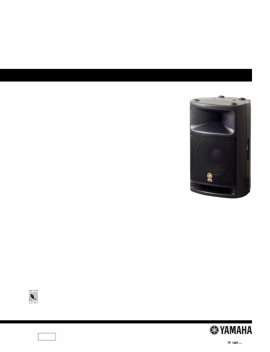
MSR400 3 ■ SPECIFICATIONS(総合仕様) • General specifications Type Bi-Amp 2-way bass reflex powered speaker Speaker unit LF: 30 cm cone HF: 4.4 cm voice coil compression driver Crossover frequency .............. 1.6 kHz (30 dB/oct.) Frequency range .................... 50 Hz-20 kHz (–10 dB) Maximum output level .......... 121 dB (1 m on axis) Directional angle ................... 90°(H)/40°(V) Dimensions (W x H x D)....... 406 x 652 x 351 mm Weight ................................... 23 kg Tripod pole diameter ............. 35 mm Accessories ............................ Power cord (AC inlet type, 2.5 m) Owner’s manual Option .................................... Stand TS-70B, TS-80(B)T and TS-90(B)T • Amp. unit Maximum output power LF: 225 W at 500 Hz, THD=1%, RL=4 Ω HF: 75 W at 5 kHz, THD=1%, RL=16 Ω Input sensitivity ..................... MIC/LINE: 36 dB/+4 dB* Input impedance .................... MIC/LINE: 10 kΩ Controls LEVEL control EQ control ......................... LOW: ± 3 dB at 55 Hz HIGH: ± 3 dB (HF) POWER switch.................. ON/OFF Connectors (all balanced) LINE input/output ............. XLR-3-31, XLR-3-32, PHONE (They are all connected in parallel and can be used as line outputs.) MIC input .......................... XLR-3-31 Indicators POWER ............................. Green LED PEAK/LIMIT .................... Red LED Power requirement U, T.................................... 120 V, 60 Hz H, B, K, O.......................... 230 V, 50 Hz A ........................................ 240 V, 50 Hz Power consumption ............... 110 W * 0 dB=0.775 V • 一般仕様 形式 バイアンプ 2 ウェイバスレフ型パワードスピーカー スピーカーユニッ ト LF : 30cm コーン HF : 4.4cm ボイスコイルコンプレッションドライバー ク ロ ス オーバー周波数........1.6kHz (30dB/oct.) 再生周波数帯域....................50Hz ~ 20kHz (- 10dB) 最大出力音圧レベル............121dB (軸上 1m) 指向角....................................90°(H) /40°(V) 最大外形寸法 (W × H × D)...406 × 652 × 351mm 重量........................................23kg 適合三脚ポール径................35mm 付属品 ................................電源コード(AC イ ン レ ッ ト 型、 2.5m) 取扱説明書 オプシ ョ ン ...................... スピーカースタンド TS-70B、 TS-80(B)T、 TS-90(B)T • アンプユニット 定格最大出力 LF : 225W at 500Hz、 THD=1%、 RL=4Ω HF : 75W at 5kHz、 THD=1%、 RL=16Ω 入力感度................................MIC/LINE: 36dB/ + 4dB* 入力インピーダンス ............MIC/LINE: 10kΩ コ ン ト ロ ール LEVEL コ ン ト ロ ール EQ コ ン ト ロ ール..............LOW :± 3dB at 55Hz HIGH :± 3dB (HF) POWER スイッチ .............ON/OFF コネクター (すべてバランス型) LINE 入出力......................XLR-3-31、 XLR-3-32、 フォン (3 つのコネクターはパラレル接 続されていますので、出力コネク タ ー と し て も 使用で き ま す。) MIC 入力 ...........................XLR-3-31 インジケーター POWER ........................緑色発光 LED PEAK/LIMIT .................赤色発光 LED 電源........................................AC100V、 50/60Hz 消費電力................................110W *0dB = 0.775V
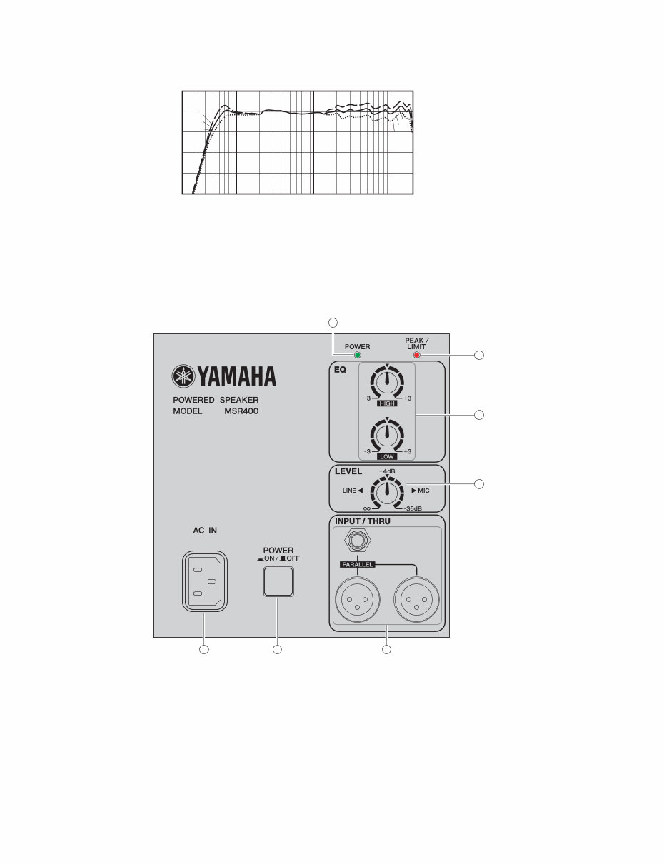
MSR400 4 ■ PERFORMANCE GRAPH(特性図) ■ PANEL LAYOUT(パネルレイアウト) • Rear Panel(リアパネル) 1 AC IN connector 2 POWER switch 3 INPUT/THRU connectors 4 LEVEL control 5 EQ control 6 PEAK/LIMIT indicator 7 POWER indicator 1 AC IN 端子 2 POWER スイッチ 3 INPUT/THRU 端子 4 LEVEL コントロール 5 EQ コントロール 6 PEAK/LIMIT インジケーター 7 POWER インジケーター 10k 1k 100 20 FREQUENCY (Hz) RESPONSE (dB) –30 –20 –10 0 +10 –40 +3 -3 0 +3 0 -3 1 2 3 7 4 5 6
MSR400 5 ■ CIRCUIT BOARD LAYOUT (ユニットレイアウト) ■ DIMENSIONS(寸法図) ■ WIRING DIAGRAM(結線図) AMP MIX INPUT SW AC INLET 150 406 351 652 197 2-M8 depth 17 Unit: mm (単位) CN203 (4P) CN201 CN202 (6P) CN103 CN102 CN101 (5P) (5P) Power Transformer CN107 (3P) CN204 CN205 CN105 (6P) CN104 (6P) BLUE YELLOW RED BLACK TWEETER WOOFER 1 2 3 4 AC.IN CN106 (3P) L N YELLOW BROWN BLUE/BLK RED/BLK + _ LF+ LF- HF+ HF- + _ GND1 GND2 (ツイーター) (ウーファー) HUM GND AMP MIX INPUT INLET AC SW
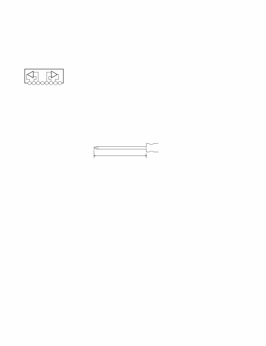
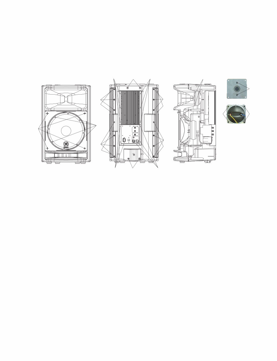
MSR400 6 ■ 分解手順 • 準備 一部のネジの取 り 外し には、軸が長い ド ラ イバーが必要で す。 1. アンプ Ass’y ( 所要時間:5 分 ) 1-1. [21] のネジ 12 本を外し、アンプ Ass’y を外します。 ( 図1) 2. リアキャビネットとフロントキャビネット ( 所要時間:10 分 ) 2-1. [18] のネジ 18 本を外し、 リアキャビネッ トからフロ ントキャビネットを外します。 ( 図 1) 3. ウーファー (所要時間:15 分 ) 3-1. リアキャビネットからフロントキャビネットを外し ます。 (2 項参照 ) 3-2. [1]のネジ4本を外し、フロントグリルを外します。 (図1) 3-3. [6] のネジ 4 本を外し、 ウーファーを外します。 ( 図 1) 4. ツィーター(所要時間:15 分) 4-1. リアキャビネットからフロントキャビネットを外し ます。 (2 項参照 ) 4-2. [9] のネジ 4 本を外し、 ツィーターと取付金具を外し ます。 ( 図 1) 4-3. [32] のネジ 2 本と [31] のワッシャー 2 個を外し、取付 金具からツィーターを外します。 ( 図 1) ■ DISASSEMBLY PROCEDURES • Preparing A screwdriver with a long shaft is required to remove some screws. 1. Amplifier Assembly (Time required: about 5 minutes) 1-1. Remove the twelve (12) screws marked [21]. The amplifier assembly can be removed. (Fig.1) 2. Rear Cabinet and Front Cabinet (Time required: about 10 minutes) 2-1. Remove the eighteen (18) screws marked [18]. The front cabinet can then be removed from the rear cabinet. (Fig.1) 3. Woofer (Time required: about 15 minutes) 3-1. Remove the front cabinet from the rear cabinet. (See procedure 2.) 3-2. Remove the four (4) screws marked [1] and the front grille. (Fig.1) 3-3. Remove the four (4) screws marked [6]. Then the woofer can be removed. (Fig.1) 4. Tweeter (Time required: about 15 minutes) 4-1. Remove the front cabinet from the rear cabinet. (See procedure 2.) 4-2. Remove the four (4) screws marked [9]. Then the tweeter can be removed with the bracket. (Fig.1) 4-3. Remove the two (2) screws marked [32] and the two washers marked [31]. Then the tweeter can be removed from the bracket. (Fig.1) ■ IC BLOCK DIAGRAM(IC ブロック図) • NJM2068L-D (AAX64880) INPUT: IC102 MIX: IC103, IC104, IC105, IC106, IC107, IC108, IC109 Operational Amplifier A + B + 1 2 3 4 5 6 7 8 OUT A –IN A +IN A –V +IN B –IN B OUT B +V 220mm or more
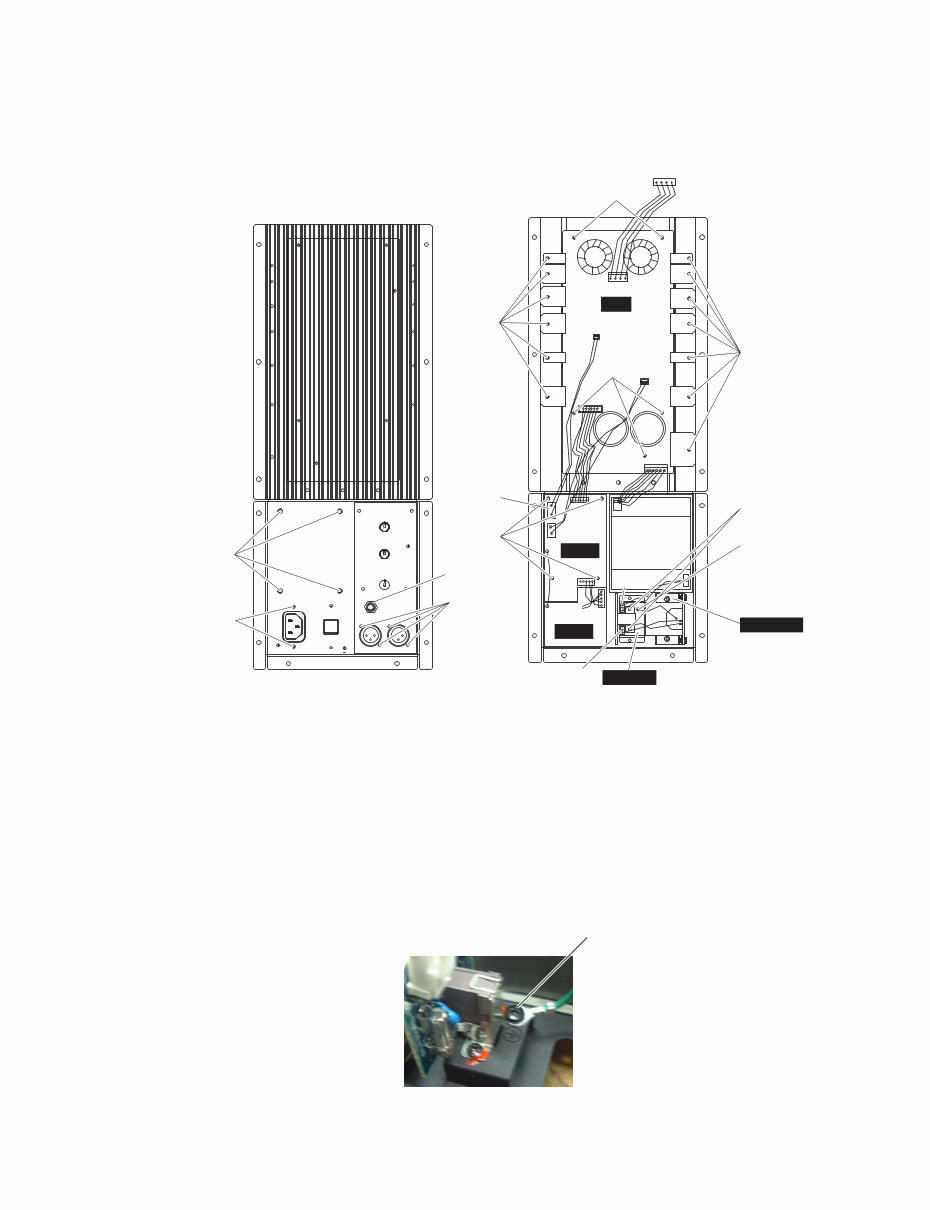
MSR400 8 5. AMP/INPUT/MIX/SW/AC INLET シート ( 所要時間:7 分 ) 5-1. アンプ Ass’y を外します。 (1 項参照 ) 5-2. 各シー ト は下記の手順で外し ます。 a) AMP シート :下表の各コネクターの接続を外して から、 ネジを外します。 ( 図 2) b) INPUT/MIX/SW/AC INLET シート : ノブおよび下表のネジを外してから、各コネクターの 接続を外します。 ( 図 2、 写真 1) 6. 電源トランス (所要時間:7 分) 6-1. アンプ Ass’y を外し ます。 ( 1 項参照) 6-2. [A18] の4本を外し、電源ト ランスを外します。(図2) 5. AMP/INPUT/MIX/SW/AC INLET Circuit Boards (Time required: about 7 minutes each) 5-1. Remove the amplifier assembly. (See procedure 1.) 5-2. Each circuit boards should be removed in proper order as follows: a) AMP circuit board: Disconnect the connectors, and then remove the screws mentioned in the table below. (Fig.2) b) INPUT/MIX/SW/AC INLET circuit boards: Remove the knobs and screws, and then disconnect the connectors mentioned in the table below. (Fig.2, Photo.1) 6. Power Transformer (Time required: about 7 minutes) 6-1. Remove the amplifier assembly. (See procedure 1.) 6-2. Remove the four (4) screws marked [A18]. The power transformer can then be removed. (Fig.2) PCB Name REF No. Description QTY AMP Circuit Board CN201/CN202/CN203/ CN204/CN205 Connector One for each (total 5) A24 Bind Head Sems Screw 3x12 MFZN2BL (AAX64760) +バインドセムス小ネジ 13 A1 Bind Head Screw 3x6 MFZN2BL (AAX64740) +バインド小ネジ 5 INPUT Circuit Board CN101 Connector 1 A16 Phone Jack Nut (--) ホーンジャックナット 1 A14 Bonding Tapping Screw-B 3x8 MFZN2BL (AAX64840) ボンディング B タイト 4 MIX Circuit Board CN102/CN103/CN104/ CN105 Connector One for each (total 4) A1 Bind Head Screw 3x6 MFZN2BL (AAX64740) +バインド小ネジ 4 SW Circuit Board CN106/CN107 Connector One for each (total 2) A1 Bind Head Screw 3x6 MFZN2BL (AAX64740) +バインド小ネジ 2 AC INLET Circuit Board CN106 Connector 1 A1 Bind Head Screw 3x6 MFZN2BL (AAX64740) +バインド小ネジ 2 A8 Bind Head Tapping Screw-B 4x8 MFZN2BL (AAX64730) +バインド B タイト 1 A13 Bind Head Screw 3x10 MFZN2BL (AAX64750) +バインド小ネジ 2 ※ There is a GND wire connected the MIX and INPUT circuit boards with solder. When removing the MIX or INPUT circuit boards, remove both of them simultaneously and remove solder on GND terminals. The MIX and INPUT circuit boards can then be separeted. ※ MIX シートと INPUT シートにはアース線がはんだ付けされています。 MIX シートまたは INPUT シート を取り外すときは両方を同時に 外し、 アース端子に付いているはんだを外します。
MSR400 9 7. ハンドル(所要時間:13 分) 7-1. リ ア キ ャ ビ ネ ッ ト を外 し ま す。 ( 2 項参照) 7-2. [17] のネジ 8 本を外し、 ハンドルを外します。 (図 1) 7. Handle (Time required: about 13 minutes) 7-1. Remove the rear cabinet. (See procedure 2.) 7-2. Remove the eight (8) screws marked [17] and then the handles can then be removed. (Fig.1) -1.5V +1.5V GND SG SIG BLUE BLK -LF +LF +HF -HF CN101 [A13] CN106 AC INLET SW CN202 [A18] [A1] CN107 [A14] CN102 [A8] [A1] CN201 CN204 [A1] CN205 [A24] [A24] [A1] [A16] CN203 speaker INPUT MIX AMP CN103 CN105 CN104 Fig.2 (図 2) [A1]: Bind Head Screw 3x6 MFZN2BL (AAX64740) +バインド小ネジ [A8]: Bind Head Tapping Screw-B 4x8 MFZN2BL (AAX64730) +バ イ ン ド B タ イ ト [A13]: Bind Head Screw 3x10 MFZN2BL (AAX64750) +バインド小ネジ [A14]: Bonding Tapping Screw-B 3x8 MFZN2BL (AAX64840) ボンディングBタイト [A16]: Phone Jack Nut (--) ホーンジャックナット [A18]: Bind Head Screw 4x8 MFZN2BL (AAX64770) +バインド小ネジ [A24]: Bind Head Sems Screw 3x12 MFZN2BL (AAX64760) +バインドセムス小ネジ ※ (--): Not available as spare parts (--): サービス用部品と して準備されていません。 Photo.1 (写真 1) [A8]
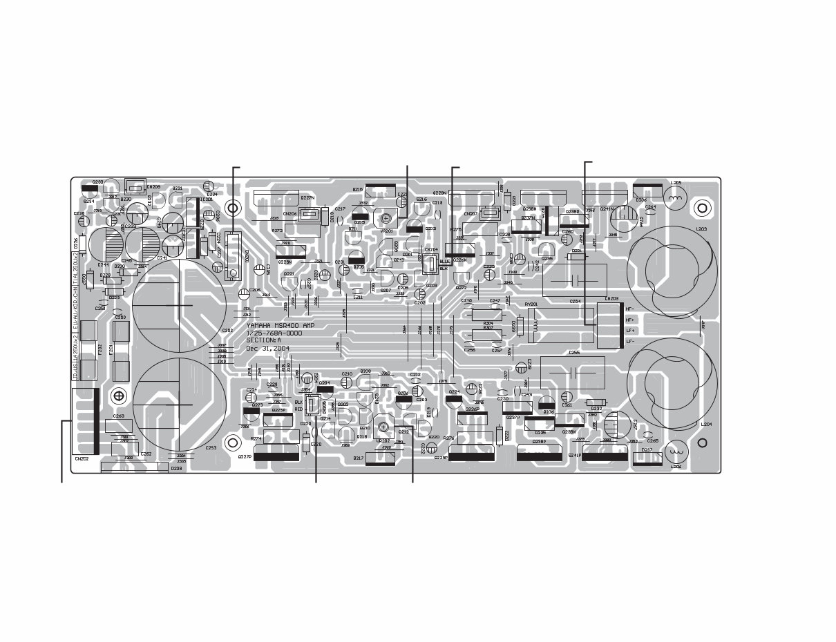
MSR400 10 ■ CIRCUIT BOARDS(シート基板図) • AMP Circuit Board to MIX-CN103 to MIX-CN104 to TWEETER (HF+/HF–) to WOOFER (LF+/LF–) IDLING ADJ. IDLING ADJ. to MIX-CN105 to TRANSFORMER Component side(部品側)
This is a comprehensive service manual designed for both professional mechanics and DIY enthusiasts. It contains specifications, parts list, exploded views, circuit board diagrams, and more. The manual provides detailed instructions for modifying, circuit bending, repairing, and restoring Yamaha products. It also includes information on entering the secret test mode for most products.
Key topics covered in almost every Yamaha service manual include:
SPECIFICATIONS
PANEL LAYOUT
CIRCUIT BOARD LAYOUT
BLOCK DIAGRAM
DISASSEMBLY PROCEDURE
LSI PIN DESCRIPTION
IC BLOCK DIAGRAM
CIRCUIT BOARDS
INSPECTION
MIDI IMPLEMENTATION CHART
OVERALL CIRCUIT DIAGRAM
PARTS LIST
This official service and repair manual is available in PDF format, ensuring high-resolution quality for printing. Upon payment, you will have instant access to the manual without any shipping delays, allowing you to commence repairs promptly.
Specifications:
Language: English
Format: PDF
Platform: Windows, MAC, Linux, etc.
If you require a service manual for another Yamaha product, feel free to inquire. Thank you for considering this manual!