Yamaha dxr8 dxr10 dxr12 dxr15 dxr full repair service manual
What's Included?
Lifetime Access
Fast Download Speeds
Online & Offline Access
Access PDF Contents & Bookmarks
Full Search Facility
Print one or all pages of your manual
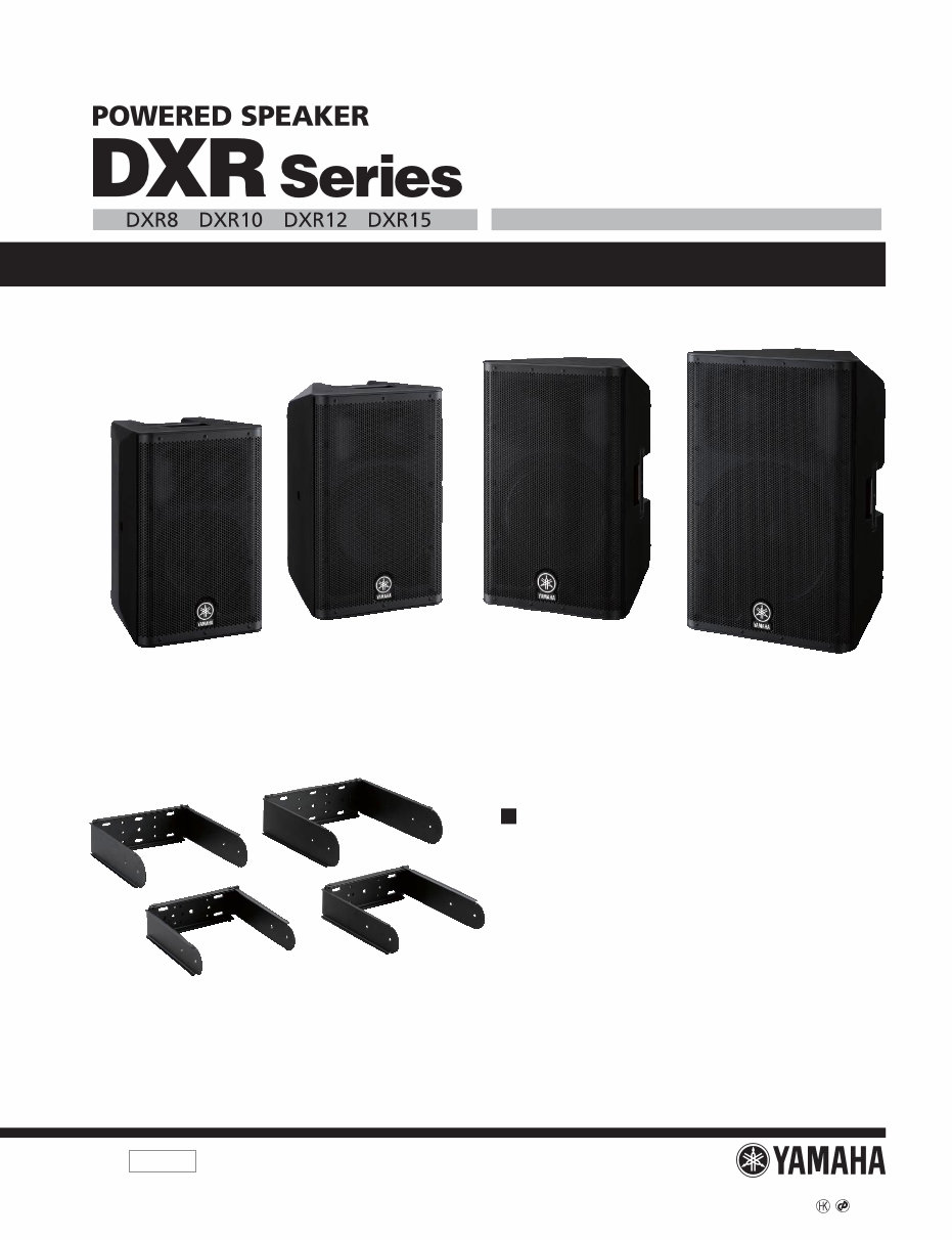
HAMAMATSU, JAPAN DXR8: 201202-71400 DXR10: 201202-81900 DXR12: 201202-92400 DXR15: 201202-102900 PA 012041 SERVICE MANUAL UB-DXR8: 201202-10500 UB-DXR10: 201202-10500 UB-DXR12: 201202-15750 UB-DXR15: 201202-15750 Copyright (c) Yamaha Corporation. All rights reserved. PDF ’12.03 SPECIFICATIONS(総合仕様) .................................... 3 PANEL LAYOUT(パネルレイアウト) ......................... 4 CIRCUIT BOARD LAYOUT(ユニットレイアウト) .... 5 DIMENSIONS(寸法図) ............................................... 7 DISASSEMBLY PROCEDURE(分解手順) ................. 8 LSI PIN DESCRIPTION(LSI 端子機能表) ................ 26 CIRCUIT BOARDS(シート基板図) .......................... 27 TEST PROGRAM(テストプログラム) ..................... 35 INSPECTIONS(検査) ............................................... 45 UPDATING(アップデート) ...................................... 55 PARTS LIST BLOCK DIAGRAM(ブロックダイアグラム) LEVEL DIAGRAM(レベルダイアグラム) CIRCUIT DIAGRAM(回路図) UB-DXR8/UB-DXR10/UB-DXR12/UB-DXR15 SERVICE MANUAL CONTENTS(目次) DXR8 DXR10 DXR12 DXR15 • POWERED SPEAKER DXR8/DXR10/DXR12/DXR15 • U BRACKET UB-DXR8/UB-DXR10/UB-DXR12/UB-DXR15 UB-DXR8 / UB-DXR10 / UB-DXR12 / UB-DXR15 U BRACKET UB-DXR12 UB-DXR8 UB-DXR10 UB-DXR15
DXR8/DXR10/DXR12/DXR15 2 WARNING Components having special characteristics are marked and must be replaced with parts having specification equal to those originally installed. IMPORTANT NOTICE This manual has been provided for the use of authorized Yamaha Retailers and their service personnel. It has been assumed that basic service procedures inherent to the industry, and more specifically Yamaha Products, are already known and understood by the users, and have therefore not been restated. WARNING : Failure to follow appropriate service and safety procedures when servicing this product may result in personal injury, destruction of expensive components and failure of the product to perform as specified. For these reasons, we advise all Yamaha product owners that all service required should be performed by an authorized Yamaha Retailer or the appointed service representative. IMPORTANT : This presentation or sale of this manual to any individual or firm does not constitute authorization certification, recognition of any applicable technical capabilities, or establish a principal-agent relationship of any form. The data provided is belived to be accurate and applicable to the unit(s) indicated on the cover. The research engineering, and service departments of Yamaha are continually striving to improve Yamaha products. Modifications are, therefore, inevitable and changes in specification are subject to change without notice or obligation to retrofit. Should any discrepancy appear to exist, please contact the distributor’s Service Division. WARNING : Static discharges can destroy expensive components. Discharge any static electricity your body may have accumulated by grounding yourself to the ground bus in the unit (heavy gauge black wires connect to this bus.) IMPORTANT : Turn the unit OFF during disassembly and parts replacement. Recheck all work before you apply power to the unit. WARNING: This product contains chemicals known to the State of California to cause cancer, or birth defects or other reproductive harm. DO NOT PLACE SOLDER, ELECTRICAL/ELECTRONIC OR PLASTIC COMPONENTS IN YOUR MOUTH FOR ANY REASON WHAT SO EVER! Avoid prolonged, unprotected contact between solder and your skin! When soldering, do not inhale solder fumes or expose eyes to solder/ flux vapor! If you come in contact with solder or components located inside the enclosure of this product, wash your hands before handling food. IMPORTANT NOTICE FOR THE UNITED KINGDOM Connecting the Plug and Cord WARNING: THIS APPARATUS MUST BE EARTHED IMPORTANT. The wires in this mains lead are coloured in accordance with the following code: GREEN-AND-YELLOW : EARTH BLUE : NEUTRAL BROWN : LIVE As the colours of the wires in the mains lead of this apparatus may not correspond with the coloured markings identifying the terminals in your plug proceed as follows: The wire which is coloured GREEN-and-YELLOW must be connected to the terminal in the plug which is marked by the letter E or by the safety earth symbol or colored GREEN or GREEN-and-YELLOW. The wire which is coloured BLUE must be connected to the terminal which is marked with the letter N or coloured BLACK. The wire which is coloured BROWN must be connected to the terminal which is marked with the letter L or coloured RED. • This applies only to products distributed by Yamaha Music U.K. Ltd. (3 wires) 印の部品は、安全を維持するために重要な部品です。交換する場合は、安全のために必ず指定の部品をご使用ください。
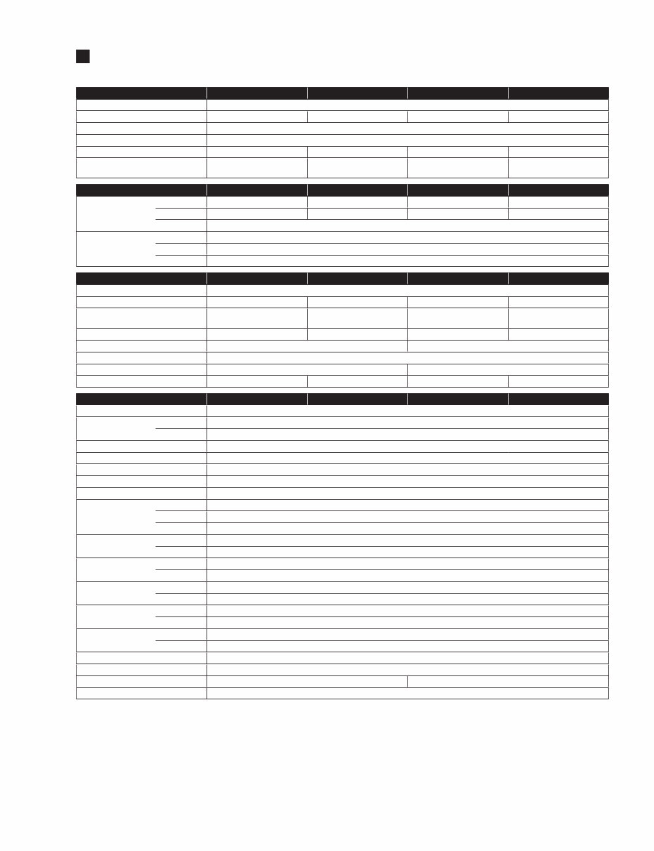
3 DXR8/DXR10/DXR12/DXR15 SPECIFICATIONS(総合仕様) General DXR8 DXR10 DXR12 DXR15 System Type 2-way, Bi-amp Powered Speaker, Bass-reflex Type Frequency Range (-10dB) 57Hz – 20kHz 56Hz – 20kHz 52Hz – 20kHz 49Hz – 20kHz Coverage Angle H90° x V60° Constant Directivity Horn Crossover Type FIR-X tuning™ (Linear Phase FIR Filter) Crossover Frequency 2.4kHz 2.3kHz 2.1kHz 2.1kHz Measured Maximum SPL (peak) IEC noise@1m 129dB SPL 131dB SPL 132dB SPL 133dB SPL Transducer DXR8 DXR10 DXR12 DXR15 LF Diameter 8" Cone 10" Cone 12" Cone 15" Cone Voice coil 2" 2" 2.5" 2.5" Magnet Ferrite HF Diaphragm 1.4" Type 1" Throat Compression Driver Magnet Ferrite Enclosure DXR8 DXR10 DXR12 DXR15 Material, Finish, Color ABS, Matte Black Floor Monitor Angle – 50° 50° Symmetrical 50° Symmetrical Dimensions (WxHxD, with rubber feet) 280×458×280 mm (11" x 18" x 11") 305×502×310 mm (12" x 19-3/4" x 12-1/4") 362×601×350 mm (14-1/4" x 23-5/8" x 13-3/4") 445×700×380 mm (17-1/2" x 27-1/2" x 15") Net Weight 13.5kg (29.8lbs) 14.6kg (32.2lbs) 19.3kg (42.5lbs) 22.5kg (49.6lbs) Handles Aluminium die-cast (Top x 1) Aluminium die-cast (Side x 2) Pole Socket 35mm with 2-way feature (0 or 7 degree) Rigging points Top x 2, Rear x 1 (Fits for M8 x 15mm eyebolts) Top x 2, Rear x 1 (Fits for M10 x 18mm eyebolts) Optional Accessory (U-bracket) UB-DXR8 UB-DXR10 UB-DXR12 UB-DXR15 Amplifier DXR8 DXR10 DXR12 DXR15 Amplifier Type Class-D Power Rating *1 Dynamic 1100W (LF: 950W, HF: 150W) Continuous 700W (LF: 600W, HF: 100W) Cooling Fan cooling, 4 speeds AD/DA 24bit 48kHz sampling Signal Processing 48bit (Accumulator: 76bit) HPF/LPF OFF, 100, 120Hz 24dB/oct HPF DSP preset D-CONTOUR: FOH/MAIN, MONITOR, OFF Protection Speaker Clip limiting, Integral Power Protection, DC-fault Amplifier Thermal, Output over current Power supply Thermal, Output over voltage, Output over current Connectors Input INPUT1: XLR3-31 x 1, INPUT2: Phone x 2 (Unbalanced), INPUT3: RCA PIN x 2 (Unbalanced) Output THRU: XLR3-32 x 1 (Parallel with INPUT1), LINK OUT: XLR x1 Input Impedance INPUT1 LINE: 12kΩ, MIC: 8kΩ INPUT2, 3 L, R: 40kΩ, MONO: 20kΩ Input Sensitivity (LEVEL: Maximum) INPUT1 LINE: +1dBu, MIC: -32dBu INPUT2, 3 -13dBu Input Sensitivity (LEVEL: Center) INPUT1 LINE: +11dBu, MIC: -22dBu INPUT2, 3 -3dBu Maximum Input Level INPUT1 LINE: +24dBu, MIC: +20dBu INPUT2, 3 +16dBu Controls LEVEL x3, LINE/MIC, HPF, D-CONTOUR, FRONT LED DISABLE, LINK MODE, POWER Idle Power Consumption 35W 1/8 Power Consumption 90W 110W Power Requirements 100V – 240V, 50Hz/60Hz 0dBu is referenced to 0.775Vrms. *1 Power rating (120V, 25°C). This is total value of individual output power. • Included Accessories · AC power cord · Owner's manual • 付属品 · 電源コード · 取扱説明書
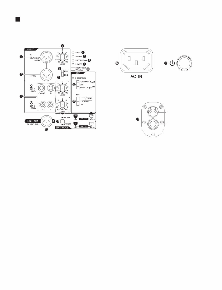
DXR8/DXR10/DXR12/DXR15 4 PANEL LAYOUT(パネルレイアウト) 7˚ 0˚ • Rear panel(リアパネル) • Tiltable pole socket (チルト可能ポールソケット) q [INPUT] jacks w [THRU] jack e [LEVEL] control r [LIMIT] indicator t [SIGNAL] indicator y [PROTECTION] indicator u [POWER] indicator i [FRONT LED DISABLE] switch o [MIC/LINE] switch !0 [D-CONTOUR] switch !1 [HPF] switch !2 [LINK OUT] jack !3 [LINK MODE] switch !4 [AC IN] socket !5 Power switch !6 Tiltable pole socket q [INPUT] 端子 w [THRU] 端子 e [LEVEL] コントロール r [LIMIT] インジケーター t [SIGNAL] インジケーター y [PROTECTION] インジケーター u [POWER] インジケーター i [FRONT LED DISABLE] スイッチ o [MIC/LINE] スイッチ !0 [D-CONTOUR] スイッチ !1 [HPF] スイッチ !2 [LINK OUT] 端子 !3 [LINK MODE] スイッチ !4 [AC IN] 端子 !5 電源スイッチ !6 チルト可能ポールソケット
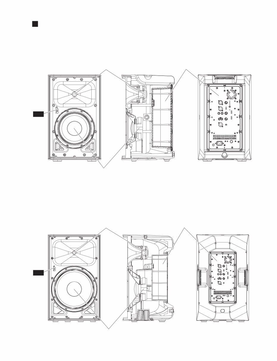
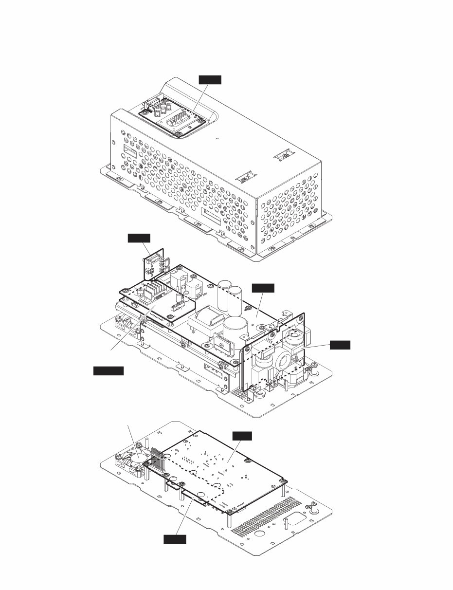
5 DXR8/DXR10/DXR12/DXR15 CIRCUIT BOARD LAYOUT(ユニットレイアウト) ● DXR8 / DXR10 ● DXR12 / DXR15 <Front view (正面)> <Right side view (右側面)> <Rear view (背面)> <Front view (正面)> <Right side view (右側面)> <Rear view (背面)> SPEAKER (WOOFER) (スピーカ(ウーファー)) ※ This figure shows the DXR8. (この図は、DXR8です。 ) ※ This figure shows the DXR12. (この図は、DXR12です。) SPEAKER (TWEETER) (スピーカ(ツイーター)) AMP ASSEMBLY (アンプ Ass’ y) SPEAKER (TWEETER) (スピーカ(ツイーター)) AMP ASSEMBLY (アンプ Ass’ y) SPEAKER (WOOFER) (スピーカ(ウーファー)) LED LED
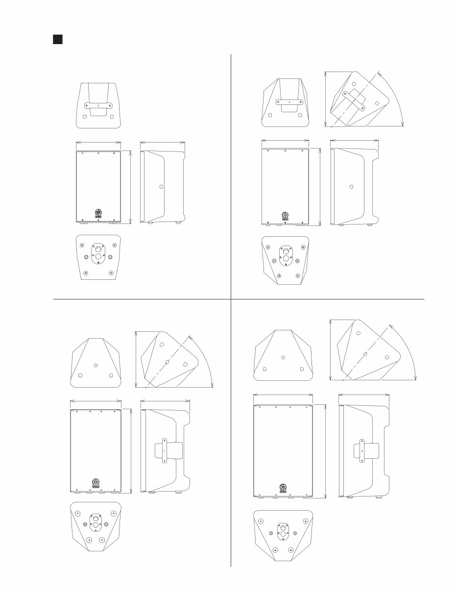
7 DXR8/DXR10/DXR12/DXR15 DIMENSIONS(寸法図) DXR8 280 280 458 DXR10 310 305 355 50° 502 Unit (単位) : mm Unit (単位) : mm DXR12 DXR15 Unit (単位) : mm Unit (単位) : mm 350 362 601 402 50° 380 445 456 700 50°
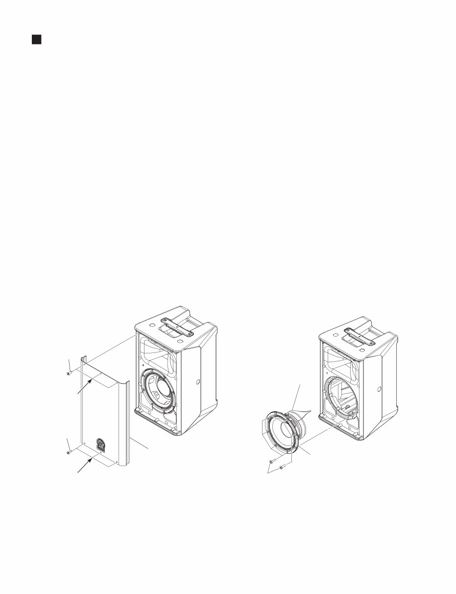
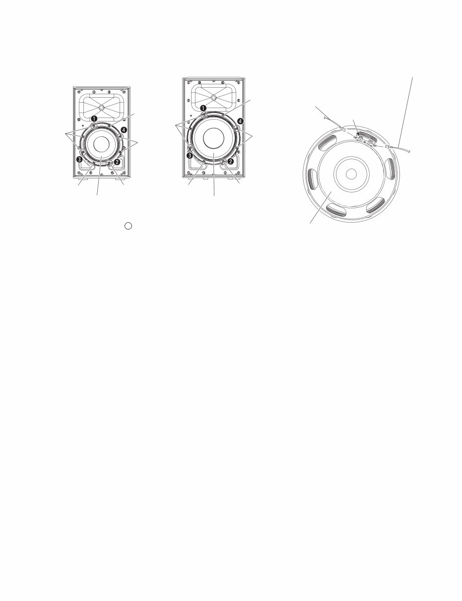
8 DXR8/DXR10/DXR12/DXR15 DISASSEMBLY PROCEDURE(分解手順) A. Disassembly of DXR8/DXR10 A-1. Metal Grille Assembly (Time required: About 1 minute) A-1-1 Remove the six (6) screws marked [150]. The metal grille assembly can then be removed. (Fig. A-1) * When installing the metal grille assembly, first tighten the two (2) priority screws as shown in Fig. A-1. A-2. Speaker (Woofer) (Time required: About 3 minutes) A-2-1 Remove the metal grille assembly. (See procedure A-1.) A-2-2 Remove the eight (8) screws marked [50]. The speaker (woofer) can then be removed. (Fig. A-2, Fig. A-3) * When installing the speaker (woofer), first tighten the four (4) priority screws in order as shown in Fig. A-3. A-2-3 Remove the LFSPOUT connector assembly (red/black) attached to the speaker (woofer) terminal. (Fig. A-2, Fig. A-4) * The speaker (woofer) is heavy. Be careful not to drop it. A. DXR8/DXR10 の分解 A-1. メタルグリル Ass'y(所要時間:約 1 分) A-1-1 [150] のネジ 6 本を外して、メタルグリル Ass'y を 外します。(図A-1) ※ メタルグリル Ass'y を取り付けるときは、図に示す優先 ネジ 2 本を先に締めてください。(図 A-1) A-2. スピーカ(ウーファー) (所要時間:約 3 分) A-2-1 メタルグリル Ass'y を外します。(A-1 項参照) A-2-2 [50] のネジ 8 本を外して、スピーカ(ウーファー) を外します。(図A-2、図A-3) ※ スピーカ(ウーファー)を取り付けるときは、優先ネジ 4本を図に示す順番で先に締めてください。(図A-3) A-2-3 スピーカ(ウーファー)端子に取り付けられてい る LFSPOUT 束線(赤/黒)を外します。 (図 A-2、図 A-4) ※ スピーカ(ウーファー)は重量がありますので、落下さ せない様に注意してください。 Fig. A-1 (図A-1) Fig. A-2 (図A-2) [50] LFSPOUT CONNECTOR ASSEMBLY (RED/BLACK) (LFSPOUT 束線 (赤 / 黒)) SPEAKER (WOOFER) (スピーカ(ウーファー)) ※ This figure shows the DXR8. (この図は、DXR8です。 ) PRIORITY SCREW (優先ネジ) PRIORITY SCREW (優先ネジ) [150] [150] METAL GRILLE ASSEMBLY (メタルグリル Ass’ y) ※ This figure shows the DXR8. (この図は、DXR8です。 )
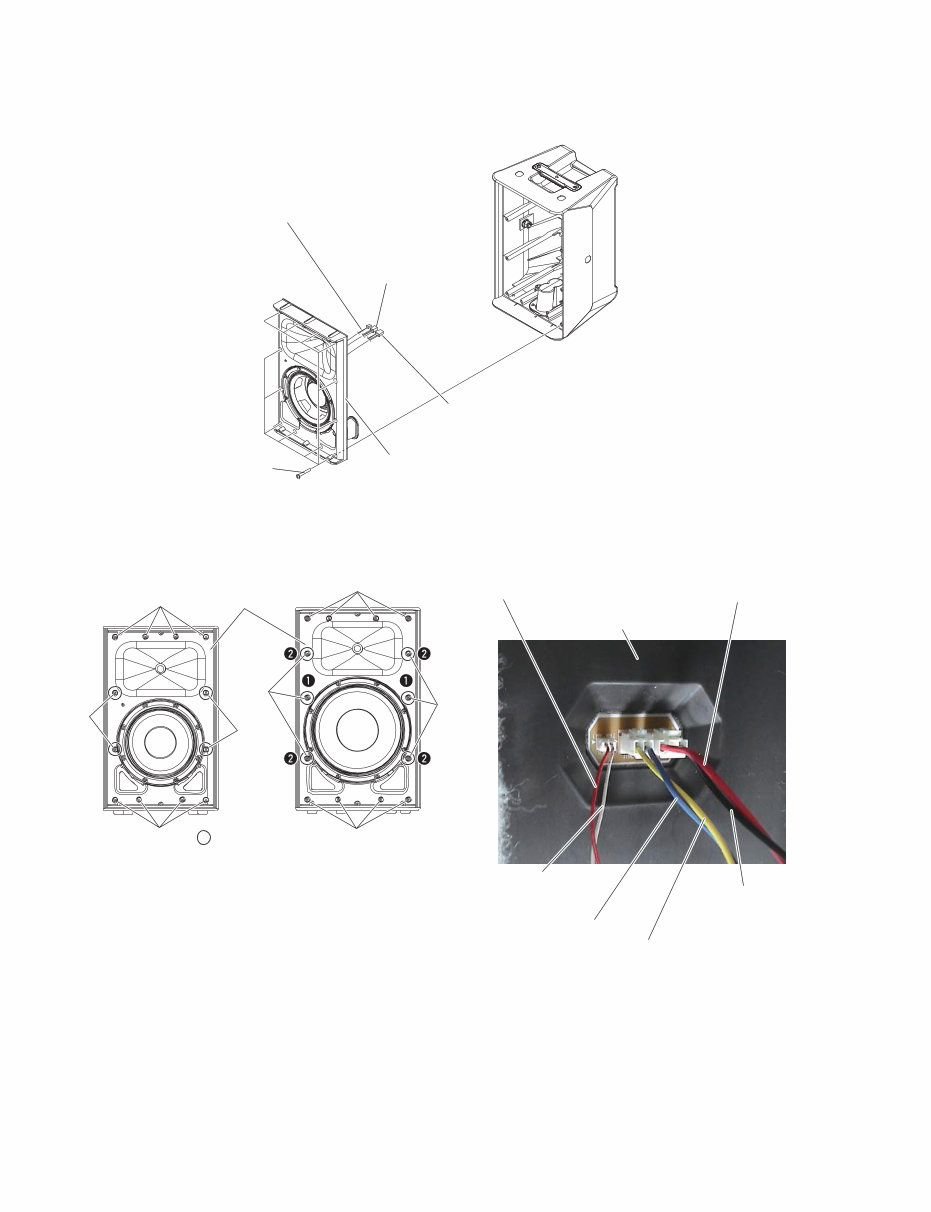
9 DXR8/DXR10/DXR12/DXR15 A-3. Baffle Assembly (Time required: About 4 minutes) A-3-1 Remove the metal grille assembly. (See procedure A-1.) A-3-2 DXR8: Remove the twelve (12) screws marked [30A]. The baffle assembly can then be removed. (Fig. A-5, Fig. A-6) DXR10: Remove the fourteen (14) screws marked [30B]. The baffle assembly can then be removed. (Fig. A-5, Fig. A-6) * DXR8: When installing the baffle assembly, first tighten the four (4) priority screws as shown in Fig. A-6. DXR10: When installing the baffle assembly, first tighten the six (6) priority screws in order as shown in Fig. A-6. A-3-3 Disconnect the connectors of the LFSPOUT connector assembly (red/black), HFSPOUT connector assembly (yellow/blue) and C&C connector assembly (red/white) from the amp assembly. (Fig. A-5, Photo A-1) * Take care not to open the baffle assembly too wide or these connector assemblies may be damaged. (Fig. A-5, Photo A-1) Fig. A-3 (図A-3) Fig. A-4 (図A-4) A-3. バッフル Ass'y(所要時間:約 4 分) A-3-1 メタルグリル Ass'y を外します。(A-1 項参照) A-3-2 DXR8: [30A] のネジ 12 本を外して、バッフル Ass'y を外 します。(図A-5、図A-6) DXR10: [30B] のネジ 14 本を外して、バッフル Ass'y を外 します。(図A-5、図A-6) ※ DXR8: バッフル Ass'y を取り付けるときは、図に示す優先ネジ 4本を先に締めてください。(図A-6) DXR10: バッフル Ass'y を取り付けるときは、優先ネジ 6 本を図 に示す順番で先に締めてください。(図A-6) A-3-3 アンプ Ass'y から LFSPOUT 束線(赤/黒)、 HFSPOUT 束線(黄/青)、C&C 束線(赤/白) のコネクターを外します。(図 A-5、写真 A-1) ※ バッフル Ass'y を開きすぎて、これらの束線を傷めない ように注意してください。(図A-5、写真 A-1) [50] [50] [50] [50] [50] [50] [50] [50] [50] SPEAKER (WOOFER) (スピーカ(ウーファー)) SPEAKER (WOOFER) (スピーカ(ウーファー)) ● DXR10 ● DXR8 [50] : PRIORITY SCREW (優先ネジ) RED MARKING (赤マーク) LFSPOUT CONNECTOR ASSEMBLY RED (+) (LFSPOUT 束線 赤 (+)) LFSPOUT CONNECTOR ASSEMBLY BLACK (–) (LFSPOUT 束線 黒 (-)) SPEAKER (WOOFER) (スピーカ(ウーファー))
This comprehensive service manual provides detailed specifications, parts list, exploded views, circuit board diagrams, and more for Yamaha products. It is an invaluable resource for both professional mechanics and DIY enthusiasts.
With topics including specifications, panel layout, circuit board layout, block diagram, disassembly procedure, LSI pin description, IC block diagram, circuit boards, inspection, MIDI implementation chart, overall circuit diagram, and parts list, this manual offers step-by-step instructions for repairing and servicing Yamaha devices.
Rest assured, this is the official service and repair manual in PDF format, ensuring high-resolution quality for printing. Instant access after payment eliminates shipping fees and waiting time, allowing for immediate repairs.
Language: English
Format: PDF
Platform: Windows, MAC, Linux, etc.
For any other Yamaha product service manual needs, feel free to reach out. Thank you!
Recently Viewed
5,521,897Happy Clients
2,594,462eManuals
1,120,453Trusted Sellers
15Years in Business
Price:
Actual Price:
Yamaha dxr8 dxr10 dxr12 dxr15 dxr full repair service manual