,
DIREC TORY
TO
MODEL H - 30 PAYLOADER PARTS MANUAL
This manual is used specifically for the following Series of H-30 PAYLOADERS.
The serial nllZIlber of a PAY LOADER consists of four parts which identify it:
:I< I. H. C. GAS
It I. H. C. DIESEL
MODEL NO.
10
11
SERIES
A
A
POWER
H
H
IMPORTANT - PLEASE READ CAREFULLY
UNIT NO.
1075
1001
(The illustrations in this manual are of typical parts only - the parts znay vary in detail. )
Each part pictured in this manual is given an identiiication nUnlber which corresponds to the iteIIl
nUIIlber in the parts lists of the group. These iteIIl nwnbers are given to identiiy the part and name of the
items wanted. Parts listed herein apply to machines beginning with serial n\lIIlber shown on the outside
cover, IlDless otherwise specified in the serial number column or at the top of the page. Figures in the
"Oty" colllIIlD indicate the nllZIlber of that part used in the g.roup -- not the total for the IIla.chine.
The bucket is always considered all the front end of the machine and right (R. H. ) or left hand (L. H. )
sides are deterIIlined by the operator's position when sitting in the seat and facing the bucket.
Always give the following information on all repair parts orders:
1. The Part Number. Name and Ouantity of IteIIls needed.
2. The Serial N\lIIlber and Model Letters of the IIlachine.
3. When ordering parts for the TransIIlissio , D, Drive Axle. P=p. Valve, or Engine, be sure to
give the SeriaL Number and Model Number of such llDits also.
4. Give the Destination and Method of Shipment desired along with any special inVOicing instructions.
* International Harvester Co. - Model U-240
It International Harvester Co. - Model UD-Z36
i
ii
- COMMERCIAL HARDWARE-
SpeciaL code numbers are listed in the part nUIIlber coLumn by the contractor. Listed
below is the coded index to be used to identify the capscrews, nuts .. flatwashers and
lockwashers. Such information shall be sufficiently compLete to enable the custoIIlers
to make the replacement from cOIIlIIlercial sources, if necessary. All special hard-
ware will have the regular six digit number.
CAPSCREWS - The letter "5" followed by the part nUIIlber indicates the diaIIleter in
16ths and the length in 8ths. S-l is fine pitch, S- 2 is coarse pitch.
EXAMPLE: S-1820 is fine pitch, 8/16" in. diaIIleter by 20/8"
long or 1/2" NF x 2-1/2" SAE - Grade ItS steel.
NUTS - The letter "H" followed by an even nUIIlber digit denotes coarse pitch and
type of nut. An odd number digit denotes fine pitch and type of nut. ReIIlainder of
part number indicates size in 16ths.
EXAMPLE: H-18 denotes fine pitch, hexagon nut, S/16"
diaIIleter or 1/2 - 20 thread. Types of nuts
are digits I lie 2 - Hex nut, 3 &: 4 - Jam Nut,
S lie 6 - Hexagon Slotted lie 7 &: 8 - Hex. Slotted
Thick.
WASHER, FLAT - The letters "WF" followed by the 1st digit denotes type, (digit
1# I is Wrought, digit 1t3 is SAE) 2nd and ~rd digit denotes bolt size of £latwasher
in l6ths.
EXAMPLE: WF-1S denotes Wrought type washer
8/16" bolt size or 1/2" bolt size.
LOCKWASHER - The letters "WL" followed by the 1st digit denotes thickness, (WL-l
is rnediuIIl, WL-2 is light and WL-4 is heavy) 2nd and 3rd digit denotes bolt size of
lockwasher in l6ths.
EXAMPLE : WL-lS denotes rnediuIIl thickness, 8/16" bolt size
or 1/2" bolt size of washer.
TABLE OF CONTENTS
NAME'
Accelerator lit Linkage Group .. ... ..... . ....... . ....... ... .... •.. . .....
Air Cleaner Group ...•... . •• . ....... . ... . ... ... ... . .... ... ...•. .. .. ..
Axle Throwout Group ..... .• .. . ... .... .. ........ .•. ..... ... .. .. ... .. •.
Body Group ..... • ...... . .......... ..... . ... . ..... . ..... ... ...• .... ...
Battery Box ...... .... .• .. ..... . ..... . .......... . ... . •... . ••.••
Floorboard lit Ladder •. . ............. . .... • ..•...•. . ••..• .... .. .
Seat • ......... .. ...• .... ................... • .......... • ... .. •.
BOOIIl - Breakout Linkage lit Bucket Group .. .. ... . .•. . .. .•.• .•..•.. . ....
Brake Connections Group .... . .• .......... .. .. . .• . ..... .. .. .. . ... • ....
Brake lit TransInission Disconnect Group .......... .. ••. . • ....... •. ... . ..
Converter Group ....... • • ... . .... • • .. . ... ... . .• ....... ••.•. . •• .......
Filter •..•.• ..... '" ...... .. .. . ........ . ... '" . . , ..... • . •.. , ..
PUIIlP - Accessory Drive .... •... . ............. . • ...............
Converter Lines .. . ... ..... .• ............... . ... . ... ... .... .... •• . .. .
* Diesel Modification .. .. . " .. '" ....... . ..•.. . ...... . .......... .. . , ....
Decal lit Tool Group ...... .• • • ..... . ......... ... .. .. ................. •
Drive Shaft Group ...... •..•.. ...... . .... .. ..... . ..... . ........ .... .. .
Drive Shaft - Upper Rear •. ...... . ............. . .... . ... . ••..• ..
Drive Shaft - Front .•• • ... .. ...... ....... . .. . .... ... .... •... .. .
Drive Shaft - Lower Rear .. .......... .... .. .. ... .. .. .... ... .• .. .
Universal ... ....... .•. ... . ........ . ....... .. ...• ...... .•. .... •
Engine Group .• ..... ... . .. .•. ..... . ....... . ...... .. .. . ....... .•... .. .
Front Axle Group .. ..... •.. .. . .... .. .. . ....... .. .. . ........ . .•. ... ...
Brake ... .. .. ... .... ••.. . ......... . ....... • ........ •... . .... ..
Differential . ..... • . ..• .... . .... . ......... . .. . ....... •.•.•. •. ..
Housing ..... •• .... .••. . ....... • .... . .• ..... . ..• ... .•. . .. . ...
Shaft lit Hub . .... .. •.• .......... . ....... . ............ . .. . ......
Fuel Tank lit Lines ...•.•• ..... • .. .. ..... ..... . ..• ....... . ...... •...•.
Gear Shift lit Linkage .. ..• .... • ..... . ... . ... ... .... •. ..... •... ..• •..•.
Hydraulic Group .•.. .. .• . .. .... ..... • .... .. ... .. .• .. .. . ..•. .• .. .. ...•
Cylinder - Boom lit Bucket ...•• . ..• ...... . ... .. ........ •..• .... •
Cylinder - Steering lit Linkage ......... ... ..... • . .. . ..... . • .....
Flow Divider . .... .. .... . " ............ . ... . " . . .... , ..•• .... ...
Hydraulic lit Steering Lines .•. . .......... . ........ . .•..•• . •...••
PUIIlP - Main ...•. . ... •. .. . ...... . .... .. .... .. .. .. .... ...•• • ...
Reservoir ..••.• .... .• .... ....... • .... ... .. . ....... . ..•...•. •.
Valve - Main Control . •. . ................ '" .. .......... • ..... ..
Main Frame Group . ...•. .. .................... . ...... .. .. ...•...••.•.
Numerical Index .• ...... ... .• .... .. ......... .. ........ . .. . ... . .•.• .•.
Parking Brake lit Linkage Group ..•. ......... •. . ........ . ... . ... ... .. ..
Radiator lit Hoses ................ ... ........... . ....... . •. '. ... ..... , . .
Rear Axle Group . . , .. ..... .. .. . , . ..... . ... , .. ... ...... .. ... , ...• .....
Brake ... .......... . .... , .. . ... , .. . ...... . .... . ..•.. .... • .. •...
Differential .... .. .. .. .... ... ... .. ..... ... ...... . ...... .... .. . . .
HOusing ... • .... ........ ... ... . .. . .. ... ........ ... ............ •
Shaft lit Hub .... ... .. .. ....... .. ~ ... .. . ..... .. ... • ... . .•. . .. . ..
Steering Drag Link . .• .... .... ... .. ........ •. .. .• . .... . .. . ..... . ......
Steering Gear Group ...... ... .. . . , . ....... , ......... . • , ..• .... .•. •... .
TransIIlission .... • . .. • ..... •...•. . .•..• .... .... .. ..... . ...... •• . , .•••
Clutch Assembly - Forward lit Reverse .. .. • •.. .. , '" ........ " •. .
Clutch AsseInbly - First Gear •.. • . , .... . . , . ..... ,: •.••• . • , •.. '"
Clutch Assembly - Second lit Third Gear ., .. , ..... . ..... .. • . . , .. . .
Rear Output Shaft ., ...• ..... • ...... • •... ... .•••.. .. .•• . , . .... . .
Valve .. .. ...... , ...• ..... . .•.. . ...• ..... . ........ ... ..... • . ..
Valve Control Group .... • .. .• . ............... .. •.• ...... • .. ..... •.. . •.
Wiring Group ...... . ... ... . ...... , ...... , .... , .. ....... .... ...... •...
PAGE
31
11
32
4-7
6
5
7
75
61
34
15-18 .
17
. 18
1.-3
79
78
36-39
36
37
39
38
8
41-47
47
43
41
45
9
29
73
59
67
65-66
69
63
71
3
79
33
10
49-55
55
51
49
53
41
57-58
19-27
26
Z4
25
27
19
35
77
* This modif ication has been prepared specificall y for the Model H-30 "PAY LOADER" Units
equipped w ith the 1. H . C . UD- 2 36 Diese .l Engine . To clearly identify the parts on these spe-
cific units, use the in d ex and group list on page 79 with the current PM-H-30 Parts Manual
and the Mo del UD-236 Engine Parts Manual.
1
N
~
.... ~
z .. ·
~a;'l
~ ...
~
t'1
~T()
fF@
41
40
t
39
22 23
t
b
ITEM
NO.
Z
2-
3
4
5
6
7
8
9
10
11
12
13
14
15
16
17
IS
19
20
21
22-
23
24
25
26
27
28
29
30
31
32
33
34
35
35
36
37
3S
39
40
41
4Z
43
44
45
46
47
48
49
50
51
PART
NO.
157833
157833H2
141566
E - 28
H - 2.8
WL-18
1572.94
S-2816
5-2.816
WL-18
H - 2.8
H - 26
WL-16
144078
144079
144068
WF-16
152.7 ' 13
5-269
5-2810
WL-IS
144062
157509
WL-16
H - 26
118491
158843
5-112.2.0
E-ll2.
157852.
118491
H - 18
WL-IB
157525
5-1814
157852.
1572.93
WL-18
H - 18
E - 28
5-2811
WL-IS
5-2816
143912
158833
157406
157509
E-1l2
14406z
WL-IS
5-2810
5-11220
l1S492-
S-IS34
WL-18
H - IS
143419
158948
15S949
5-11012
WL-110
H-110
5-11220
WL-1l2
H-112
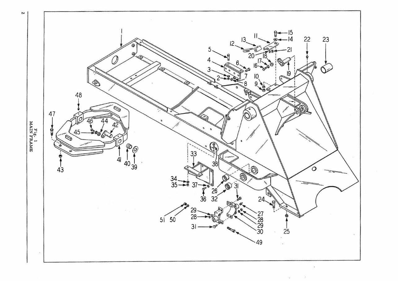
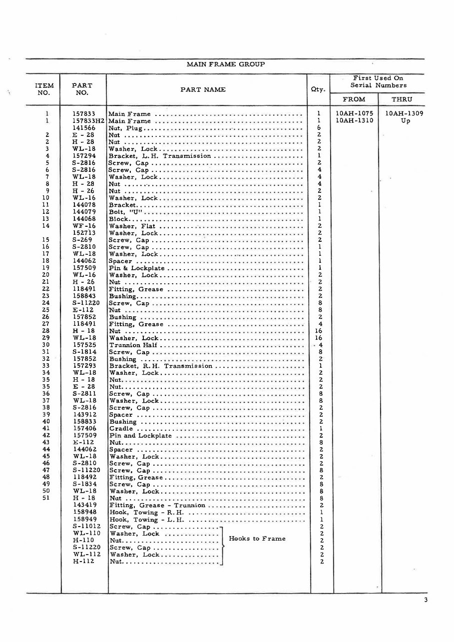
MAIN FRAME GROUP
PART NAME
Main Frame ... ..... . . , ........ . ......... . ...... . .
Main Frame .. .. .. ... . .. .. .. ... ....... .. .. .. .. . .. .
Nut, Plug .• ..... ..•. ........ . ... ' ... . ... . .. . .. . ... .
Nut .•...••... ... . ....... ..... ..... . ... .. .. . .. ....
Nut ...• ...... •..• ........ ... ..... . ..... .... .... ..
Washer, Lock .. .... . ..... .. .. . .......... ... .. .. .. .
Bracket, L. H. Transmission . .......... . .... . .. ... .
Screw, Cap ..... .... .. . ........ . .... .. .. ... .. . . . . .
Screw, Cap .... .. . .. . .......... ...... .. .......... .
Washer, Lock •. .. . •. . ............ . ......... .. .... .
Nut .• .... " .... ........... • ... .. , .. ... .. , . . ..... . . .
Nut ... . ...... ... .. .. •... . . , ...... , ... . ,., ..... . . .
Washer, Lock ... , . . . ... ... .. . .. .. ... ... .... . ... .. .
Bracket .......... ... .. . ... .... ..... ...... ' .... .. . .
Bolt, "U" .. .. .. ... . ... .. . .. .... . ....... . ... .. .. . . .
Block ...... • .... . . , . . . .. ... . , . ..... , ....... . .... . .
Washer, Flat ......... . ' . .. .... . ......... . ..... .. . .
Washer, Lock .... . ... ....... . ... , • .... , .. . ..... . . .
Screw, Cap ........... .. : . .. .... . .. . ........ . ... . .
Screw, Cap ........... .. ......... .. ....... . ... .. . .
Washer, Lock .. ....... . .. .. ......... .. ... ...... ... .
Spacer ..•.. " .... , ... .. .. ............... . ....... .
Pin &t Lockplate ....... .. .. . ... . ...... .. .. ... ... .. .
Washer, Lock ......... ..... ... .... .. .. . ... . .. .... .
Nut .................. .......... , .. .. .. .. .. ...... .
Fitting, Grease ....... ...... . .. ... ....... .. .... . . .
Bushing ..• .. .• ..... ........... . .. . ....... . ........
Screw, Cap . .. ..... .• .. ... .. .... .. ... ... ... . .. .. ..
Nut . .. .. ... .. .. .. .. . .. .. , .... . .......... .... .... .
Bushing . .• ... .. . ... . .... , ... .. ...• .......... .. ...
Fitting, Grease .. ..... . .. , .... . ..... .. ...... . .... .
Nut .... • ........ .... .. . , .............. .. .. . .. . .. .
Washer, Lock ... .• ..... .. . "" ..... , ..... .. .... .. .
Trunnion Half . ..... . ... . ... ... .. .. .... .. . .. . .. . .. .
Screw, Cap .. ... .. . .. .. ..... . .... .. ....... . .... .. .
Bushing .• .... . . . " . ....... ... ... . ..... . .. . . , .. . . .
Bracket, R. H. Transmission ... .. .. ... ........... •.
Washer, Lock .... .. .. . , .... .... ... ... . ... . ...... . .
Nut .... . ......... .. ... ..... .. ..... ... .... . ..... . •.
Nut •.•..•.• ..... .. ......... .. . ... .. .......... . ....
Screw, Cap .. .•. ......... ... ............... . .. ... .
Washer, Lock •... .. . .. . .. . .. .. .... ... . .......... ..
Screw, Cap .. . .. .... ... ... ....................... .
Spacer ..•• ..... . .. .. .. .. ..... .. .. •.. .... .... .....
Bushing ............ ...... .. ..... . ..... .. ... .. ... .
Cradle ..•• ........ .. , . .... •... .. ..... .. ..... . .. ..
P in and Lockplate .. ..... . .... .. ... .. .. . ...... . .. . .
Nut ... ... ... ..... . ...... . .... ........... . ..... . .. .
Spacer ....... .. . .. .. ..... .. . . ' " ...... . .. ... .... .
Washer, Lock . ... ... .. ... .. .. ...... . •. ... .. .. .... .
Screw, Cap ... .. .. .. ...... . .. ..... ... .. .. .. . .... . .
Screw, Cap .... .... . ... . ...... ... .. .. .. ... .. .. . .. .
F itting, Grease .. . .. .. . ... . .... ... .... ... . ........ .
Sc rew, Cap .. . .. ........ . ...... . .... .. ....... . ... .
Washer, Lock .•. ...... . .. . ... .. ..... ... .. .. .. . ... .
Nut ...... ... .. ... ..... .. .. ..... ... .............. .
F itting, Grease - Trunnion .... .. .. .. .. . ..... .. .... .
Hook, Towing - R. H ...... .... . .. . .. . ............. .
Hook, Towing - L. H ..•... .. .. . .... , ........ .• .... .
Screw, cap ........ .. ... .. .. }
Washer, Lock .. ... .. .. .... .
Nut. • . . . . . . . . . . . . . . . . . . . . .. . Hooks to Frame
Screw, Cap ......... . ... . . . .
Washer, Lock .... . ... . .. , .. ,
Nut .......... ..... . .... . , .. .
Qty .
1
1
6
2.
2
2
1
2
4
4
4
2
2
1
1
1
2
2
2.
1
1
1
1
2.
2
2
2
8
8
2
4
16
16
4
B
2
1
2
2
2
8
8
2
2
Z
1
Z
8
Z
2
2
8
2
8
8
8
2
1
1
2
2
2
2
2
2
First Used On
Serial Numbers
FROM
10AH-I075
10AH-1310
THRU
10AH-1309
Up
3
ITEM
NO.
1
1
2
3
4
5
6
7
8
9
10
11
12
13
14
15
16
16
17
18
19
20
21
Z2
23
24
25
26
27
28
29
30
31
3Z
33
34
4
PART
NO.
158155
165500
139430
H - 16
WL-16
WF-36
5-168
158184
5-269
158187
158189
WL-16
5-Z66
158019
WL-16
5-267
158191
166408
5-265
WL-16
158190
WL-16
WF-16
5-266
158188
WL-16
5-266
H - 16
WL-16
158185
104467
104469
153619
153640
168857
153618
158186
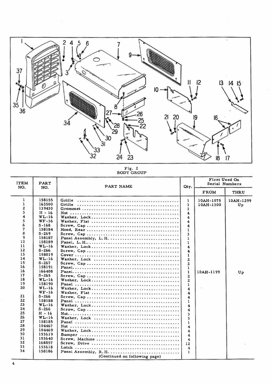
Fig. Z
BODY GROUP
PART NAME
21 20
\ i.
,
Grille .. .. .. ... .. .. ....... • .... . ...•..• ..... . ....
Grille . •. . .. . • .... •. ... .. .. .. . • .... ... .. ..... ....
Grouunet .. .•.. . ... . .. . ...... . .... .. •• ... ..•. ... ..
Nu.t . ... .. .. ......... .. ... . .... .. .. ............ . . .
Washer, Lock .•. . ... ...... .. ..•. ...•. .. .. .. . .... ..
Washer, Flat ..• ...... • ................ .. ... ..... .
Screw, Cap •..•• ...... ..... • .... ....... .. ... . .... .
Hood, Rear • .......... . ........ . ..• .. ..•. ... ..... .
Screw, Cap ................ •. ... ......... . ..... . ..
Panel Assembly, L. H ............. .... ... .. ....... .
PaneL, L.H • ............... . ..• • ........ . ... . ... .. •
Washer, Lock ... .. . ....... . •. . • ...... . ... ~ . ...... .
Screw, Cap .•... .. .... • .... .. •. .. .... ... .. . .......
Cover .... . • ...... .. ...•.•.• .... . ....... .. : .... •. ..
Washer, Lock . ... . ... ... ...... .. .... .. ....... .. . .
Screw, Cap ................. ..... .. ..... . .... .. .. .
PaneL. . .. . ... '" .. .. .. .. '" .... . .. . .......... . .. . .
PaneL. .... • .... •.• .... • •. . ... .... .. ..•. ... • .... ...
Screw, Cap .•... .... .... • .... •. ... .............. ..
Washer, Lock .• ....... •.• .... .. .. .. .. .. . ......... .
Panel .... •. ...... ..... .. .. . ...... . ... . ..... . .....
Washer, Lock ..... • ....... . ......... .... . ...... . ..
Washer, Flat .... •.•.. ...... ..... . .... .. ....... ...
Screw, Cap •...• ........ • .............. .... .. .... .
PaneL ....... •.. .. ..... . ....... . ... . .......... . .. .
Washer, Lock •.. .. .... •. . .. .. ...... . ........ ... ...
Screw, Cap .... .. . ... . .. .. ....... ... ... .. ........ .
Nu.t ...... •• ...... .• .... . ........ . .. . ..... . ... ... ..
Washer, Lock .• ................... .. .• ....... .. ..
Panel ... .. .. .. ......... . ..•. .. .. ......... . ... . ...
Nu.t . .. . ....... . .......... . ..... .. .. .. ....... . . . . .
Washer , Lock .. ... ..... .. ................ . ... . .. . .
Bu.mper ............. ... . .............. .. .. ... . .. .
Screw, Machine ...... ........... . ............. . .. .
Screw, Drive ........ . ... .. . .. .. .......... .. .. .. . .
Latch ......... . ..... • ..... . .... ... .. .. .. ... ......
PaneL Assembly, R. H . ....... .... ............... . . .
(Continu.ed on foLLowing p ag e)
13 14 15
\\}
. ~
16 .
cP~
i \
18 17
First Used On
Serial NllIIlbers
Qty. ~~------ -r------ ---
FROM
1 10AH-1075
1 10AH-1300
1
4-
4
4.
4.
1
3
1
1
4.
4
1
2
2
1
1 10AH-1l99
Z
Z
1
4.
4
4.
1
4-
4.
3
3
1
4.
4
4.
4.
12
4.
1
THRU
10AH-1299
Up
Up
ITEM
NO.
35
36
37
ITEM
NO.
1
l
3
4
5
6
7
S
9
10
11
lZ
13
14
15
16
17
18
19
PART
NO.
WL-1l2
WF-312
5-1125Z
H-1l2
165499
5-1S12
WL-1S
WF-lS
PART
NO.
WL-16
WF-16
S-Z6S
15SZ1S
162404
141566
S-Z67
WF-16
WL-16
15SZZ1
S-268
WF-16
WL-16
5-269
WL-16
WF-16
H - 26
158222
S-lS14
WL-IS
H - 18
H - IS
WL-lS
5-1S12
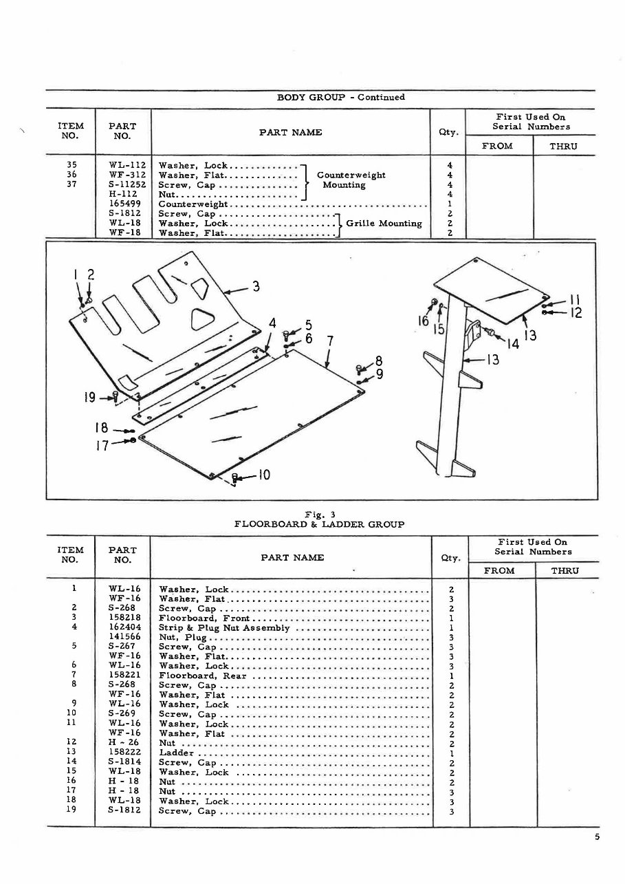
BODY GROUP - Continued
PART NAME
Washer, LOCk • ............ }
Washer, Flat .......... .... Counterweight
Screw, Cap ......... ...... Mounting
Nut .... • ........ • .........
Counterweight .................................... .
Screw, cap ................ ..... . }
Washer, Lock ....... . ............ Grille Mounting
Washer, Flat ...... .......... . ... .
Fig. 3
FLOORBOARD &. LADDER GROUP
PART NAME
Qty .
4
4
4
4
1
l
Z
Z
Qty .
Washer, Lock ...................... ......... ..... . 2
Washer, Flat ....................... .... . . . . . . . . . . . 3
Screw, Cap .......... . .. . ............ ...... .. ..... 2
Floorboard, Front ....... ........... . .............. 1
Strip &. Plu.g Nllt Assembly ......................... 1
Nut, PIllg .... ......... .. ........... . ............. . 3
Screw, Cap ......... ..... ............. ....... ..... 3
Washer, Flat ........ . ....... ...................... 3
Washer, Lock ..... ............................... . 3
Floorboard, Rear .......... ....... .... . ..... .. .... 1
Screw, Cap .... .... .. ... .... ...................... 2
Washer, Flat ..................................... 2
Washer, Lock . ................................... 2
Screw, Cap ..... .................................. 2
Washer, Lock ....... ...... .... .......... ....... ... 2
Washer, Flat ..................................... 2
Nut. ... ..... ..................... . ...... . ........ 2
Ladder. . .. .. .. . . . . ...... . .... . . . . . .. . . . . . . . . . . . .. 1
Screw, Cap ......... ........ .. . ... ................ 2
Washer, Lock ........ ................... ......... 2
Nllt ............ • ....... ...... .................... 2
Nut ............................... ..... .. ... ..... 3
Wa.sher, Lock ....................... ........... ... 3
Screw, Cap .... ...... . ........... .. ............... 3
First Used On
Serial Numbers
FROM THRU
First Used On
Serial Nllmbers
FROM THRU
5
6
ITEM
NO.
1
2
3
4
5
6
7
8
9
10
11
PART
NO.
158160
5-21012
WL-II0
H-210
WL-110
H-210
5-21016
5-21018
WL-II0
H-210
158198
158164
160558
127514
168751
E - 34
154049
158161
159837
159231
158162
161060
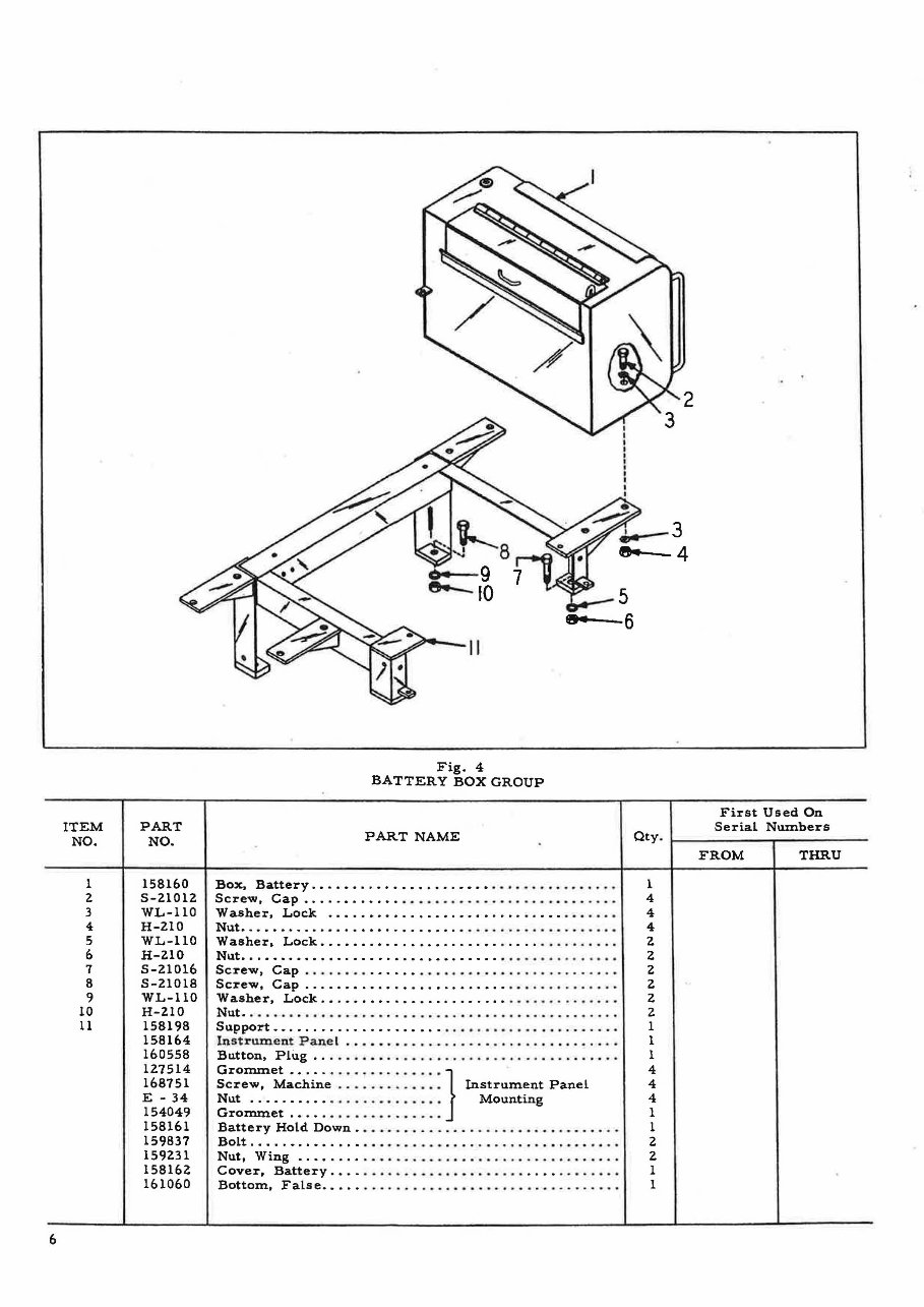
Fig. 4
BATTERY BOX GROUP
PART NAME
Box. Battery .•..•• ...... •. . •..••.• ...•...• . .. . ....
Screw. Cap ..... •... . ..... .. ... .• .. .. ... .. . ..... ..
Washer. Lock • .... •..•...•.•. • •• ........ •. .• .....
Nut ..•.•• .......... •• ..... •.•.. . .. ..... . .. . ... ....
Washer, Lock ••.•...••..•• . ...... •. . .... ..... . .. ..
Nut ••.••.•.• .......... •... • ••.•..•. .. ... • ........ .
Screw, Cap ...... . ..•...•. .. .... .. • .. ... . ...... . ..
Screw, Cap ...••••.•.•.•.. . •..•..•.. ........... ...
Washer, Lock .• .•• •••... • .......... • ........... . ..
Nut ... ... . .... . .... • ..... . ...... .. . .. ............ .
Support •• ............. • .... •. ...... .. .... ... . .. ...
In str um e nt: Panel . ..• .. " . . .. ...... . .... , .. . .... . . .
Button, Plug •. .. . .. .... .. ..•. . .. .. ... . .. . ... . ...•.
GroIIlIIlet ••... ... .. ..... • .. • }
Screw, Machine ... . .... .. ... Instrument Panel
Nut ....... • .• ... . .. •• ...... Mounting
GroIIlIIlet .•... . .. •... ... ... .
Battery Hold Down .. .... .. .... ...... .. ... .. ... .... .
Bolt ..... •. , ••..•. •. ....... ... .. .. . .......... .....
Nut, Wing ...• . ..• ........... . .. . •... . ....... ... ..
Cover, Battery .•.. ..... .... .. . •. .•. ... .... .. ..... .
Bottom, False ..... .. .... .. .. . , ....... .. .. ...... • •.
2
First Used On
Serial Numbers
Qty. ~ ---------r------ ---
1
4
4
4
2
2
2
2
2
2
1
1
1
4
4
4
1
1
2
2
1
1
FROM THRU
You're Reading a Preview
What's Included?
Lifetime Access
Access PDF Contents & Bookmarks
Print one or all pages of your manual