

JCB Robot 190, 190HF, 1110, 1110HF, 190T, 190THF, 1110T, 1110THF Skid Steer Loader Service Repair Workshop Manual
What's Included?
Fast Download Speeds
Online & Offline Access
Access PDF Contents & Bookmarks
Full Search Facility
Print one or all pages of your manual

Service
Manual
ROBOT
190, 1110
PUBLISHED BY THE
TECHNICAL PUBLICATIONS DEPARTMENT
OF JCB SERVICE; ©
WATERLOO PARK, UTTOXETER,
STAFFORDSHIRE, ST14 5PA, ENGLAND
Tel. ROCESTER (01889) 590312
PRINTED IN ENGLAND
Publication No. 9803/8530 issue 8
Copyright © 2004 JCB SERVICE
All rights reserved. No part of this publication may be reproduced, stored in
a retrieval system, or transmitted in any form or by any other means, elec-
tronic, mechanical, photocopying or otherwise, without prior permission
from JCB SERVICE.
General Information 1
Care & Safety 2
Routine Maintenance 3
Attachments A
Body & Framework B
Electrics C
Controls D
Hydraulics E
Transmission F
Brakes G
Tracks J
Engine K
R

Introduction
This publication is designed for the benefit of JCB Distributor Service Engineers who are receiving, or have received, training by
JCB Technical Training Department.
These personnel should have a sound knowledge of workshop practice, safety procedures, and general techniques associated
with the maintenance and repair of hydraulic earthmoving equipment.
Renewal of oil seals, gaskets, etc., and any component showing obvious signs of wear or damage is expected as a matter of
course. It is expected that components will be cleaned and lubricated where appropriate, and that any opened hose or pipe
connections will be blanked to prevent excessive loss of hydraulic fluid and ingress of dirt. Finally, please remember above all
else SAFETY MUST COME FIRST!
The manual is compiled in sections, the first three are numbered and contain information as follows:
1 = General Information - includes torque settings and service tools.
2 = Care & Safety - includes warnings and cautions pertinent to aspects of workshop procedures etc.
3 = Routine Maintenance - includes service schedules and recommended lubricants for all the machine.
The remaining sections are alphabetically coded and deal with Dismantling, Overhaul etc. of specific components, for example:
A = Attachments
B = Body & Framework ...etc.
The page numbering in each alphabetically coded section is not continuous. This allows for the insertion of new items in later
issues of the manual.
Section contents, technical data, circuit descriptions, operation descriptions, etc. are inserted at the beginning of each
alphabetically coded section.
All sections are listed on the front cover; tabbed divider cards align directly with individual sections on the front cover for rapid
reference.
Where a torque setting is given as a single figure it may be varied by plus or minus 3%. Torque figures indicated are for dry
threads, hence for lubricated threads may be reduced by one third.
'Left Hand' and 'Right Hand' are as viewed from the rear of the machine facing forwards.
9803/8530 Issue 1

i
Contents Page No.
Identifying your Machine 1 - 1
Torque Settings
- Unsealed Hoses and Adapters 2 - 1
- ‘O’ Ring Face Seal System 2 - 3
- ‘Torque Stop’ Hose System 2 - 4
Service Tools
- Numerical List 3 - 1
- Body and Framework 4 - 1
- Electrics 5 - 1
- Hydraulics 6 - 1
Sealing and Retaining Compounds 8 - 1
Section 1 General Information
9803/8530
Section 1
i
Issue 2*
*
1 - 1
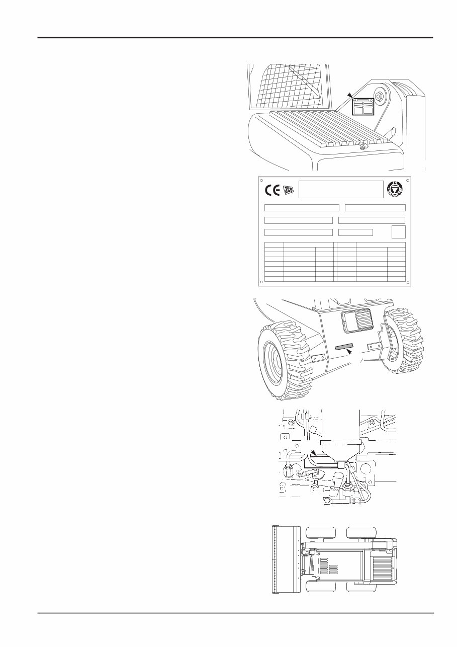
Machine Identification Plate
The machine identification plate A is located as shown. It is
stamped with the serial numbers of the major individual
units.
Typical Vehicle Identification Number (VIN)
SLP 190 S B V E 888001
World Manufacturer Identification
Machine Model
Machine Type (S = Standard, H = High-flow)
Build Type (A = Canopy, B = Cab)
Year of Manufacture:
W = 1998 2 = 2002
X = 1999 3 = 2003
Y = 2000 4 = 2004
1 = 2001 5 = 2005
Manufacturer Location (E = England)
Product Identification Number (PIN)
Unit Identification
The chassis serial number is stamped on the front face of
the chassis as shown at B.
The engine serial number is stamped on a label C on the
side of the cylinder block.
If any of the major units are replaced with new ones, the
relevant serial number on the Machine Identification Plate
will be superseded. Either stamp the plate with the new
number or stamp out the old number.
Typical Engine Identification Number
AR 50262 U 500405 P
A B C D E
A Engine Type
AR = 4 cylinder naturally aspirated - low emission
AK = 4 cylinder turbo - low emission
RE = 4 cylinder naturally aspirated - low emission stage 2
RG = 4 cylinder turbo - low emission stage 2
Where the service procedure differ between the engine
types, the text and/or illustration will specify.
B Build Number
C Country of Origin
D Engine Sequence Number
E Year of Manufacture
Left Side, Right Side
In this manual, 'left' X and 'right' Y mean your left and right
when you are seated correctly in the machine.
Section 1 General Information
9803/8530
Section 1
1 - 1
Issue 4
Identifying your Machine
1 2 3 4 5 6 7
1
2
3
4
5
6
7
378270
B
378260
A
S181760
C
378210
Y
X
CONSTRUCTOR MADE IN UK
JCB COMPACT PRODUCTS LIMITED
HAREWOOD ESTATE, LEEK ROAD,
CHEADLE, STOKE ON TRENT,
UNITED KINGDOM ST10 2JU
Vehicle Identification No. Product Identification No.
ENGINE SERIAL No. WEIGHT
PUMP SERIAL No. YEAR OF MANUFACTURE
MODEL 80/1269/EEC MODEL 80/1269/EEC
POWER KW R.P.M. POWER KW R.P.M.
160
170
170 HF
35.7
37.3
37.3
2600
2800
2800
817/19702
1CX HF 1CX
190
190 HF
1110
1110 HF
37.3 2800 2800
59.7
59.7
68.6
68.6
2200
2200
2200
2200 35.7 2600 160 HF
2800
37.3
180 44.7 2800 180 HF 44.7

2 - 1
Section 1 General Information
9803/8530
Section 1
2 - 1
Issue 1
Torque Settings
Use only where no torque setting is specified in the text. Values are for dry threads and may be within three per cent of the
figures stated. For lubricated threads the values should be REDUCED by one third.
UNF Grade 'S' Bolts
Bolt Size Hexagon (A/F) Torque Settings
in (mm) in Nm kgf m lbf ft
1
/4 (6.3)
7
/16 14 1.4 10
5
/16 (7.9)
1
/2 28 2.8 20
3
/8 (9.5)
9
/16 49 5.0 36
7
/16 (11.1)
5
/8 78 8.0 58
1
/2 (12.7)
3
/4 117 12.0 87
9
/16 (14.3)
13
/16 170 17.3 125
5
/8 (15.9)
15
/16 238 24.3 175
3
/4 (19.0) 1
1
/8 407 41.5 300
7
/8 (22.2) 1
5
/16 650 66.3 480
1 (25.4) 1
1
/2 970 99.0 715
1
1
/4 (31.7) 1
7
/8 1940 198.0 1430
1
1
/2 (38.1) 2
1
/4 3390 345.0 2500
Metric Grade 8.8 Bolts
Bolt Size Hexagon (A/F) Torque Settings
in (mm) in Nm kgf m lbf ft
M5 (5) 8 7 0.7 5
M6 (6) 10 12 1.2 9
M8 (8) 13 28 3.0 21
M10 (10) 17 56 5.7 42
M12 (12) 19 98 10 72
M16 (16) 24 244 25 180
M20 (20) 30 476 48 352
M24 (24) 36 822 84 607
M30 (30) 46 1633 166 1205
M36 (36) 55 2854 291 2105
Note: All bolts used on JCB machines are high tensile and must not be replaced by bolts of a lesser tensile specification.

2 - 2
BSP Adapters with Bonded Washers.
Adapter Size Spanner size Torque Settings
in mm Nm kgf m lbf ft
1
/8 11 20 2.0 15
1
/4 19 34 3.5 25
3
/8 22 75 7.6 55
1
/2 27 102 10.4 75
5
/8 30 122 12.4 90
3
/4 32 183 18.7 135
1 38 203 20.7 150
1
1
/4 305 31.1 225
1
1
/2 305 31.1 225
SAE Adapters with ‘O’ rings.
Adapter Size Torque Settings
in Nm kgf m lbf ft
7
/16 20 2.0 15
9
/16 35 3.6 26
3
/4 81 8.3 60
7
/8 108 11.0 80
1
1
/16 183 18.7 135
1
5
/16 298 30.4 220
1
5
/8 380 38.8 280
Hydraulic Coned BSP Hoses.
Hose Size Spanner size Torque Settings
in mm Nm kgf m lbf ft
1
/8 14 14 1.4 10
1
/4 19 27 2.7 20
3
/8 22 40 4.0 29
1
/2 27 55 5.6 40
5
/8 30 65 6.6 48
3
/4 32 95 9.7 70
1 38 120 12.2 88
1
1
/4 189 19.3 139
1
1
/2 244 24.9 180
Section 1 General Information
9803/8530
Section 1
2 - 2
Issue 1
Torque Settings
2 - 3
‘O’ Ring Face Seal System
Adaptors screwed into valve blocks
Adaptors screwed into valve blocks, etc. seal onto an 'O' ring which is compressed into a 45
o
seat machined in the face of the
tapped port.
Common Spanner Size (A/F) Tightening Torque
Adaptor Size mm in. Nm lbf ft
1/4” BSP 19 0.75 18 13
3/8” BSP 22 0.875 31 23
1/2” BSP 27 1 49 36
5/8” BSP 30 60 44
3/4” BSP 32 1.25 81 60
1” BSP 38 1.5 129 95
1 1/4” BSP 206 152
SAE SAE Port Common Spanner Size (A/F) Tightening Torque
Tube Size Thread Size mm in. Nm lbf ft
4 7/16 - 20 15.9 0.625 20 - 28 16.5 - 18.5
6 9/16 - 18 19.1 0.750 46 - 54 34 - 40
8 3/4 - 16 22.2 0.875 95 - 105 69 - 77
10 7/8 - 14 27.0 1.063 130 - 140 96 - 104
12 1.1/16 - 12 31.8 1.250 190 - 210 141 - 155
16 1.5/16 - 12 38.1 1.500 290 - 310 216 - 230
20 1.5/8 - 12 47.6 1.875 280 - 380 210 - 280
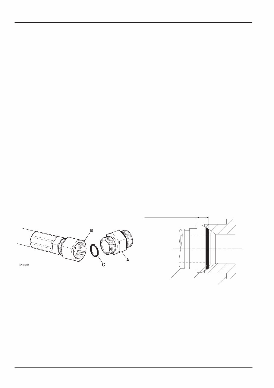
Hoses Screwed onto Adaptors
Hoses B screwed onto adaptors A etc. seal onto an 'O' ring C which is compressed into a 45
o
seat machined in the face of the
adaptor port.
Common Spanner Size (A/F) Tightening Torque
Hose Size mm in. Nm lbf ft
1/8” BSP 14 14 10
1/4” BSP 19 0.75 24 18
3/8” BSP 22 0.875 33 24
1/2” BSP 27 1 44 33
5/8” BSP 30 58 43
3/4” BSP 32 1.25 84 62
1” BSP 38 1.5 115 85
1 1/4” BSP 189 140
1 1/2” BSP 244 180
Section 1 General Information
9803/8530
Section 1
2 - 3
Issue 1
Torque Settings
B
A
C
A438691
Dimension will vary depending
on torque applied.
2 - 4
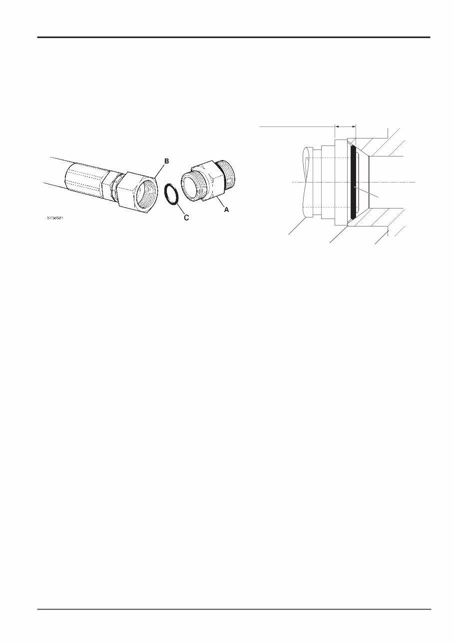
'Torque Stop' Hose System
'Torque Stop' Hoses B screwed onto adaptors A etc. seal onto an 'O' ring C which is compressed into a 45
o
seat machined in
the face of the adaptor port. To prevent the ‘O’ ring being damaged as a result of over tightening, 'Torque Stop' Hoses have an
additional shoulder, which acts as a physical stop.
Common Spanner Size (A/F) Tightening Torque
Hose Size mm in. Nm lbf ft
1/8” BSP 14 14 10
1/4” BSP 19 0.75 27 20
3/8” BSP 22 0.875 40 30
1/2” BSP 27 1 55 40
5/8” BSP 30 65 48
3/4” BSP 32 1.25 95 70
1” BSP 38 1.5 120 89
1 1/4” BSP 189 140
1 1/2” BSP 244 180
Section 1 General Information
9803/8530
Section 1
2 - 4
Issue 1
Torque Settings
A438701 D
B
A
C
Minimum dimension fixed
by shoulder D.

3 - 1
Numerical List
Page No.
1406/0011 Bonded Washer 6 - 2
1406/0018 Bonded Washer 6 - 2
1406/0021 Bonded Washer 6 - 1/6 - 2
1406/0029 Bonded Washer 6 - 2
1604/0003 Adapter 6 - 2
1604/0004 Adapter 6 - 2
1604/0006 Adapter 6 - 1/6 - 2
1606/0003 Adapter 6 - 2
1606/0004 Adapter 6 - 2
1606/0007 Adapter 6 - 2
1606/0008 Adapter 6 - 2
1606/0009 Adapter 6 - 2
1612/0006 Adapter 6 - 1
331/22966 Pump Drive Alignment Tool 6 - 4
4101/0251 Threadlocker and Sealer 8 - 1
4101/0451 Threadlocker 8 - 1
4101/0552 Threadlocker and Sealer (High Strength) 8 - 1
4101/0651 Retainer (High Strength) 8 - 1
4102/0551 High Strength Threadlocker 8 - 1
4102/1201 Multi-Gasket 8 - 1
4104/0251 Activator (Aerosol) 8 - 1
4104/0253 Activator (Bottle) 8 - 1
4104/1310 Hand Cleaner 4 - 1
4104/1557 JCB Cleaner/Degreaser 8 - 1
816/00189 Blanking Cap 6 - 2
816/00190 Blanking Cap 6 - 2
816/00193 Blanking Cap 6 - 2
816/00196 Blanking Cap 6 - 2
816/00197 Blanking Cap 6 - 2
816/00294 Blanking Cap 6 - 2
816/15118 Pressure Test Adapter 6 - 1
816/20008 Adapter 5 - 2
816/50043 'T' Adapter 6 - 3
816/55038 Pressure Test 'T' Adapter 6 - 1
816/55040 Pressure Test 'T' Adapter 6 - 1
816/60096 'T' Adapter 6 - 3
826/01099 Rivet Nut 4 - 3
826/01101 Rivet Nut 4 - 3
826/01102 Rivet Nut 4 - 3
826/01103 Rivet Nut 4 - 3
826/01104 Rivet Nut 4 - 3
826/01105 Rivet Nut 4 - 3
892/00047 'T' Adapter 6 - 3
892/00048 'T' Adapter 6 - 3
892/00055 Blanking Plug 6 - 2
892/00056 Blanking Plug 6 - 2
892/00057 Blanking Plug 6 - 2
892/00059 Blanking Plug 6 - 2
892/00060 Blanking Plug 6 - 2
892/00074 Female Connector 6 - 3
892/00075 Female Connector 6 - 3
892/00077 Female Connector 6 - 3
892/00137 Hose 6 - 2
892/00223 Hand Pump 6 - 2
892/00253 Pressure Test Kit 6 - 1
892/00255 Pressure Test Adapter 6 - 1
892/00256 Pressure Test Adapter 6 - 1
892/00257 Pressure Test Adapter 6 - 1
Page No.
892/00258 Pressure Test Adapter 6 - 1
892/00259 Pressure Test Adapter 6 - 1
892/00260 Pressure Test Adapter 6 - 1
892/00261 Pressure Test Adapter 6 - 1
892/00262 Pressure Test 'T' Adapter 6 - 1/6 - 2
892/00263 Pressure Test 'T' Adapter 6 - 1
892/00264 Pressure Test 'T' Adapter 6 - 1
892/00265 Pressure Test 'T' Adapter 6 - 1
892/00268 Flow Monitoring Unit 6 - 1
892/00269 Sensor Head 6 - 1
892/00270 Load Valve 6 - 1
892/00271 Adapter 6 - 1
892/00272 Adapter 6 - 1
892/00274 Adapter 6 - 2
892/00275 Adapter 6 - 1
892/00276 Adapter 6 - 1
892/00277 Adapter 6 - 1
892/00278 Gauge 6 - 2
892/00279 Gauge 6 - 2
892/00281 AVO Meter 5 - 1
892/00282 Shunt 5 - 1
892/00283 Tool Kit Case 5 - 1
892/00284 Tachometer 5 - 1
892/00285 Hydraulic Oil Temperature Probe 5 - 1
892/00286 Surface Temperature Probe 5 - 1
892/00706 Test Probe 6 - 2
892/00842 Glass Lifter 4 - 1
892/00843 Folding Stand 4 - 1
892/00844 Long Knife 4 - 2
892/00845 Cartridge Gun 4 - 1
892/00846 Glass Extractor (Handles) 4 - 2
892/00847 Nylon Spatula 4 - 3
892/00848 Wire Starter 4 - 2
892/00849 Braided Cutting Wire 4 - 2
892/00858 Pump Support Bracket 6 - 2
926/15500 Rubber Spacer Blocks 4 - 3
992/09300 Spanner 6 - 3
992/09400 Spanner 6 - 3
992/09500 Spanner 6 - 3
992/09600 Spanner 6 - 3
992/09700 Spanner 6 - 3
992/12300 12V Mobile Oven 4 - 1
992/12400 Static Oven - 2 Cartridge 4 - 1
992/12600 Static Oven - 6 Cartridge 4 - 1
992/12800 Cut-Out Knife 4 - 2
992/12801 "L" Blades 4 - 2
993/55700 Direct Glazing Kit 5 - 1
993/68100 Slide Hammer 6 - 3
The following parts are replacement items for kits and would
normally be included in the kit numbers quoted above.
Replacement items for kit no. 892/00253
892/00201 Replacement Gauge 6 - 1
892/00202 Replacement Gauge 6 - 1
892/00203 Replacement Gauge 6 - 1
892/00254 Replacement Hose 6 - 1
Section 1 General Information
9803/8530
Section 1
3 - 1
Issue 2*
Service Tools
*
4 - 1
Section B - Body and Framework
Section 1 General Information
9803/8530
Section 1
4 - 1
Issue 1
Service Tools
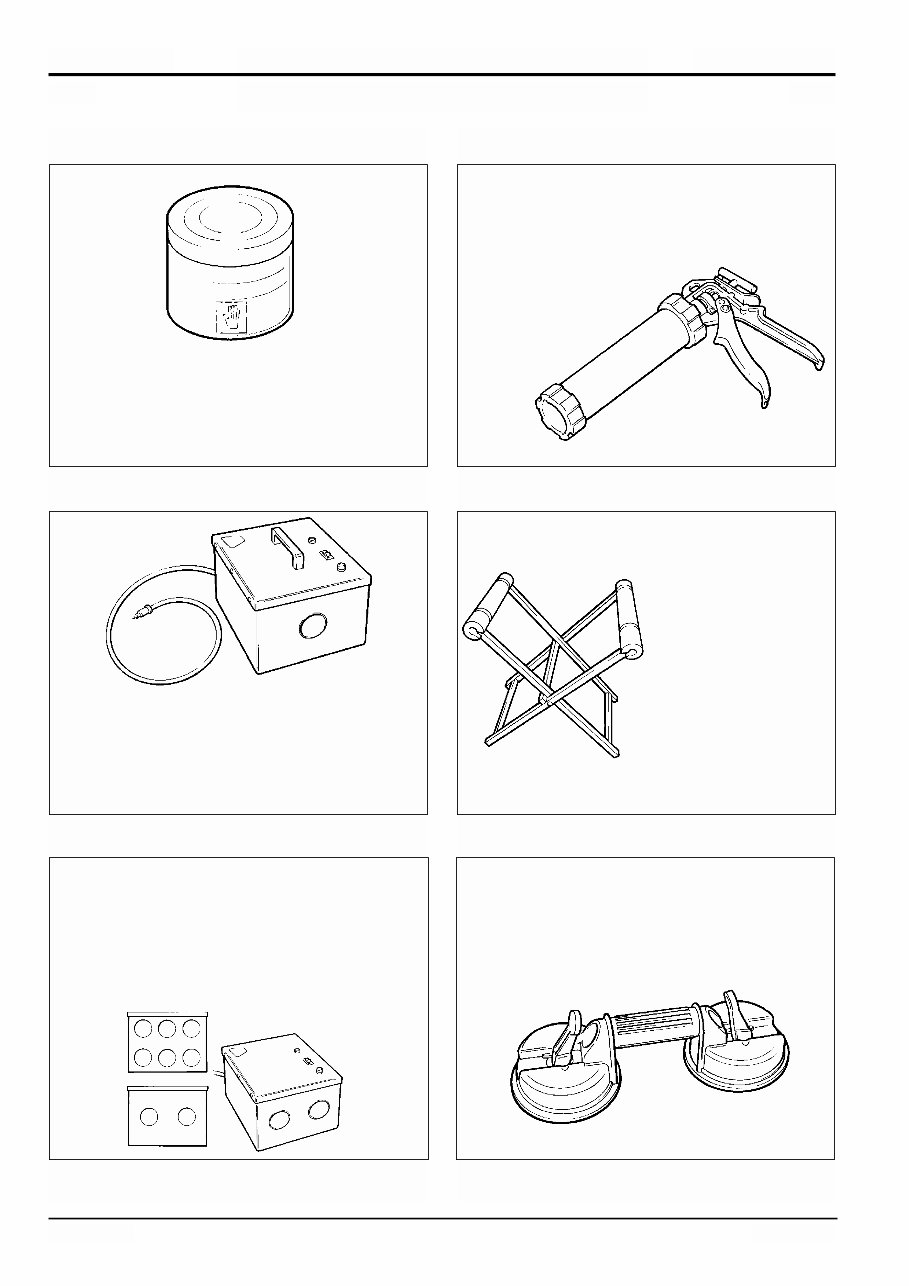
Cartridge Gun - hand operated - essential for the
application of sealants, polyurethane materials etc.
JCB part number - 892/00845
S186240
Hand Cleaner - special blend for the removal of
polyurethane adhesives.
JCB part number - 4104/1310
(454g; 1 lb tub)
S186270
S186250
12V Mobile Oven - 1 cartridge capacity - required to
pre-heat adhesive prior to use. It is fitted with a male
plug (703/23201) which fits into a female socket
(715/04300).
JCB part number - 992/12300
Folding Stand for
Holding Glass -
essential for preparing
new glass prior to
installation.
JCB part number -
892/00843
S186280
S186300
240V Static Oven - available with 2 or 6 cartridge
capacity - required to pre-heat adhesive prior to use.
No plug supplied. Note: 110V models available upon
request - contact JCB Technical Service.
JCB part number:
992/12400 - 2 Cartridge x 240V
992/12600 - 6 Cartridge x 240V
Glass Lifter - minimum 2 off - essential for glass
installation, 2 required to handle large panes of glass.
Ensure suction cups are protected from damage
during storage.
JCB part number - 892/00842
S186260
You're Reading a Preview
What's Included?
Fast Download Speeds
Online & Offline Access
Access PDF Contents & Bookmarks
Full Search Facility
Print one or all pages of your manual
$31.99
Viewed 97 Times Today


Secure transaction
What's Included?
Fast Download Speeds
Online & Offline Access
Access PDF Contents & Bookmarks
Full Search Facility
Print one or all pages of your manual
$31.99
These manuals cover the following machine models and serial numbers:
- Robot 190, 190HF / 1291500 to 1294999
- Robot 1110, 1110HF / 1291500 to 1294999
- Robot 190T, 190THF / 1407000 to 1409999
- Robot 1110T, 1110THF / 1407000 to 1409999
These manuals are valuable resources for both professional technicians and first-time owners or DIY enthusiasts. They provide comprehensive information necessary to perform procedures correctly, from routine maintenance to preventive care. By following the guidelines in this service manual, users can save time and money by preventing premature failure and unnecessary repairs.
Manual Contents:
- General Information
- Care and Safety
- Routine Maintenance
- Attachments
- Body and Framework
- Electrics
- Controls
- Hydraulics
- Transmission
- Brakes
- Tracks
- Engine
File Format: PDF
Compatibility: All Versions of Windows & Mac
Language: English
Requirements: Adobe Reader & Win


