6625 Skid Loader SN 7605 and Later Equipped with Perkins 204-30 Engine SERVICE PARTS MANUAL ® Form No. 907286
Introduction All parts should be obtained from or ordered through your GEHL Dealer. When ordering service parts, specify the correct part number, full description, quantity required, the unit model number and serial number. The model and serial numbers for this unit are on a decal located inside the right chassis riser, between the lift arm and lift cylinder. “Right” and “Left” are determined from a position sitting on the seat and facing forward. GEHL® Company reserves the right to make changes or improvements in the design or construction of any part of the unit without incurring the obligation to install such changes on any previously delivered units. NOTE: On original tire replacement, company policy prohibits the sale of replacement tires for all GEHL machinery. Replacement wheel sets are available and tire size information is called out with the wheel sets to facilitate replacement tire selection. ALL REPLACEMENT TIRES MUST BE PURCHASED LOCALLY. NOTE: Replacement batteries are not provided by the GEHL Company. For battery specifications, refer to the pages titled “Battery & Engine Electrial Wiring." ALL REPLACEMENT BATTERIES MUST BE PURCHASED LOCALLY. Refer to the abbreviations table located on this page for the various fastener descriptions. Standard attaching hardware torque values are also provided on the inside back cover. Items shown in the parts list that do not have part numbers are shown for reference purposes only and are NOT available for purchase. Dimensions are in inches unless otherwise specified. All cap screws or bolts are grade 5, cadmium or zinc plated; hexagon nuts for grade 5 screws or bolts are grade B; hexagon nuts for other screws or bolts are grade A, unless otherwise specified. Refer to the Operator’s Manual for additional information regarding GEHL attachments and accessories. NOTE: The following abbreviations may be used herein: AR ........ As Required ALT ....... Alternate ASSD ...... Assembled ASSY ...... Assembly CB ........ Carriage Bolt CS ........ Cap Screw FHSCS ..... Flat Head Slotted Counter Sunk HFLS ...... Hex Flange Serrated HWHTC ..... Hex Washer Head Thread Cut HYD ....... Hydraulic ID ........ Inside Diameter INCL ...... Included JN ........ Jam Nut L ......... Lock Washer LH ........ Left Hand LN ........ Lock Nut N......... Nut (Hex Head) NF ........ National Fine (Thread) NILN ...... Nylon Insert Lock Nut P ......... Plain Washer PKG ....... Package REF ....... Reference RHMS ...... Round Head Machine Screw SHCS ...... Socket Head Cap Screw SHSS ...... Socket Head Set Screw SUPT ...... Support TFS ....... Thread Forming Screw THD ....... Thread THMS ...... Truss Head Machine Screw UNF ....... Unified National Coarse
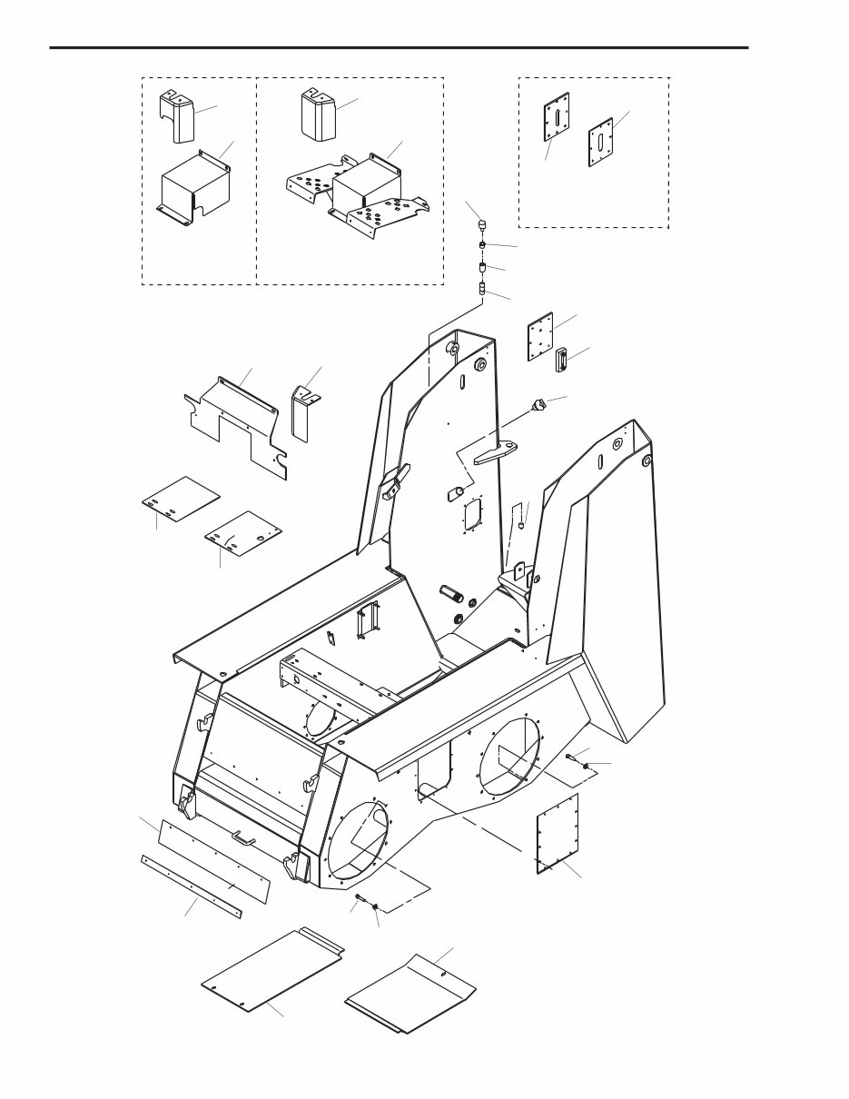
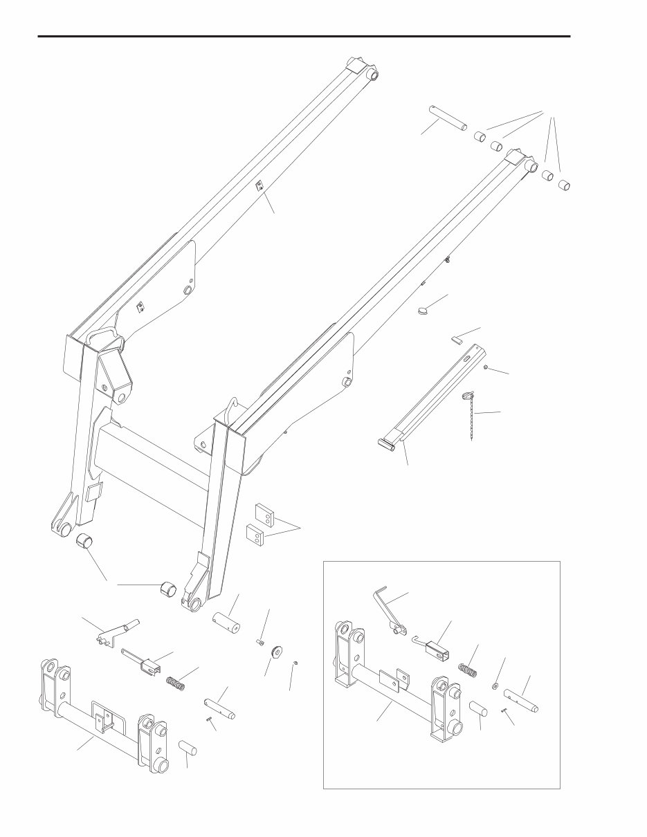
Table of Contents INTRODUCTION ................................................... inside front cover DECAL LOCATIONS ............................................................. 1 MAIN LOADER COMPONENTS CHASSIS & ACCESS COVERS .................................................... 5 LIFT ARM & GEHL QUICK-TACH™ SYSTEM ......................................... 7 GRILLE & FUEL TANK............................................................ 9 AXLES, DRIVE CHAINS & RELATED COMPONENTS.................................. 11 HYDROSTATIC SYSTEM ........................................................ 13 HYDRAULICS ................................................................. 15 LIFT/TILT HYDRAULICS ......................................................... 17 AUXILIARY HYDRAULICS ....................................................... 19 FRAME MOUNTED FRONT HYDRAULICS .......................................... 21 HIGH FLOW HYDRAULICS....................................................... 23 DIESEL ENGINE ............................................................... 25 AIR CLEANER & MUFFLER ...................................................... 27 RADIATOR & OIL COOLER....................................................... 29 TANDEM PUMP CONTROLS ..................................................... 31 THROTTLE CONTROLS ......................................................... 33 TRACTION CONTROLS ......................................................... 35 LIFT/TILT CONTROLS........................................................... 39 HAND BRAKE ................................................................. 43 ROPS, SEAT & ENGINE COVER .................................................. 45 RESTRAINT BAR .............................................................. 47 SOUND DEADENING ........................................................... 49 INSTRUMENT PANEL, WIRING & COMPONENTS .................................... 51 STANDARD LIGHTS, WIRING & COMPONENTS ..................................... 53 BATTERY & ENGINE ELECTRICAL WIRING ......................................... 55 HYDRAULIC COMPONENTS LIFT CYLINDER................................................................ 57 TILT CYLINDER ................................................................ 58 GRAPPLE CYLINDER ........................................................... 59 PLANETARY GEARCASE ........................................................ 61 BOOST CONTROL ............................................................. 62 DRIVE MOTOR ................................................................ 63 TANDEM PUMP ................................................................ 65 SINGLE GEAR PUMP ........................................................... 67 DUAL GEAR PUMP ............................................................. 68 MAIN CONTROL VALVE ......................................................... 69 DIFFERENTIAL RELIEF VALVE ................................................... 70 SELF-LEVELING VALVE ......................................................... 71 SOLENOID VALVE ............................................................. 73 ATTACHMENTS UTILITY AND LIGHT MATERIAL BUCKETS .......................................... 74 68 INCH DIRT AND CONSTRUCTION BUCKET ...................................... 75 UTILITY FORK ................................................................. 76 68 INCH INDUSTRIAL BUCKET AND GRAPPLE ...................................... 77 65 & 68 INCH INDUSTRIAL BUCKET AND GRAPPLE.................................. 79 PALLET FORKS................................................................ 81 UTILITY GRAPPLE ............................................................. 83 INDEX ....................................................................... 85 O-RING TABLE, COUPLING & ADAPTER TORQUE TABLE ............................. 91 TORQUE SPECIFICATIONS .......................................... inside back cover
DECAL LOCATIONS GENERAL INFORMATION CAUTION ALWAYS follow safety precautions on decals. Replace decals if they become damaged or if the unit is repainted. If repainting, BE SURE that all applicable decals are affixed in their proper locations. Decal location information is provided to assist in the proper selection and application of new decals, in the event the original decals become damaged or the machine is repainted. For correct replacement of decals, compare the location photographs to your machine BEFORE starting to refinish the unit. Check-off each required decal using the illustration reference number to find the part number, description and quantity in the list. Refer to the appropriate illustration for replacement locations. NOTE: Refer to the SAFETY chapter of the Operator’s Manual for the specific information provided on all of the various safety decals. NEW DECAL APPLICATION Surfaces MUST be free from dirt, dust, grease and other foreign material before applying the new decal. To apply a solid-formed decal, remove the smaller portion of the decal backing paper and apply this part of the exposed adhesive backing to the clean surface while maintaining proper position and alignment. Slowly peel off the other portion of the backing paper while applying hand pressure to smooth-out the decal surface. PAINT FINISH Use the following list to order paint for refinishing: 906213 One Gal. Yellow 906323 One Qt. Charcoal Grey 906317 One Gal. Charcoal Grey 906214 6 (12 oz. Spray Cans) Yellow 906318 6 (12 oz. Spray Cans) Grey 907286/AP0199 1 PRINTED IN U.S.A. SL6625 - DECALS
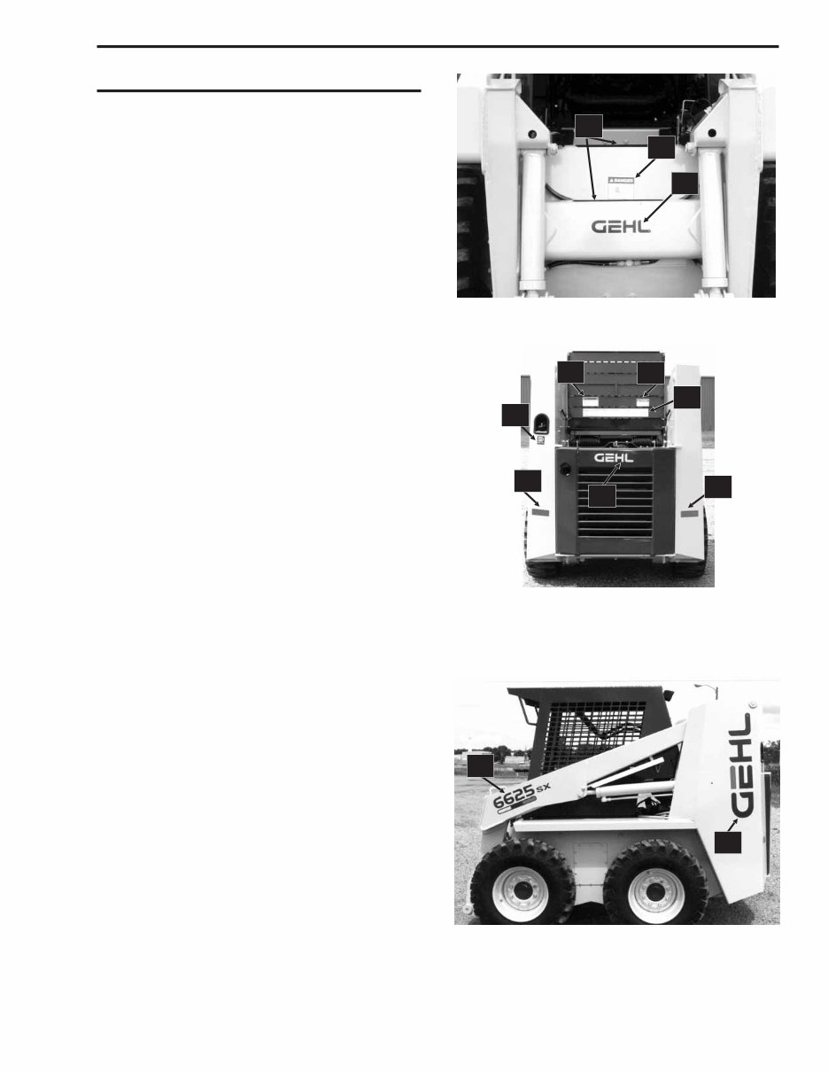
DECAL LIST Decals may be purchased individually or in kit form. This listing is repeated on each decal page for your convenience. Ref Part No. No. Description 122958 Decal Kit 1 056859 Coolant Mixture 2 067493 Red Reflector Strip 3 072794 Hydraulic Oil Symbol 4 072797 Diesel Fuel Symbol 5 072798 Coolant Under Pressure 6 072853 Lift/Tilt Lever Operation 1 7 072854 Traction Lever Operation 1 8 073075 Slow-Fast (Rabbit-Turtle) Symbol 9 073076 Brake Operation 10 073458 Non-Skid Strip 11 079362 Hydraulic Oil Level 12 088790 Auxiliary Hydraulics Operation 1 13 091033 WARNING - Jump Starting Loader 14 091035 DANGER - Lift Arm Raised 15 091050 DANGER - Rotating Component 16 093202 DANGER - Avoid Electrical Contact 17 073366 IMPORTANT- Locate Manual Here 18 093367 WARNING - Owner’s Responsibility 19 093474 WARNING-General Safety Precautions 20 093477 WARNING-Overhead Guard Safety Pin 21 093479 WARNING - Carry Load Low 22 093483 WARNING - Carry Load Low 23 093484 DANGER - Heating Unit Grounding 24 093506 Operating Capacities 25 094951 Made in U.S.A 26 121030 Non-Skid Strip 27 122289 GEHL - On Grille 28 122432 GEHL - On Liftarm Front 29 122616 GEHL - On Vertical Riser 30 122718 WARNING - Quick-Tach Locking Pin 31 123378 Forward-Reverse Lever 2 32 123379 Forward-Reverse Auxiliary Lever 2 33 123380 Lift Pedal Operation 2 34 123381 Tilt Pedal Operation 2 35 123598 Dual Pump Switch 36 123912 WARNINGS 37 127275 Model Identification (SL6625SX) 127276 Model Identification (SL6625DX) 38 129267 Service Guide 1 T-Bar Models Only 2 Hand/Foot Models Only PRINTED IN U.S.A. 2 907286/AP0199 SL6625 - DECALS 14 28 10 27 23 38 13 2 2 4 37 29
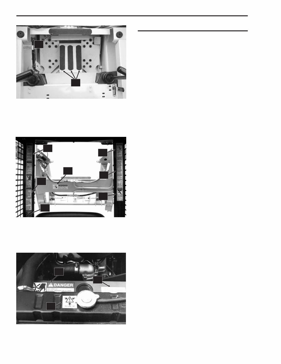
DECAL LIST Decals may be purchased individually or in kit form. This listing is repeated on each decal page for your convenience. Ref Part No. No. Description 122958 Decal Kit 1 056859 Coolant Mixture 2 067493 Red Reflector Strip 3 072794 Hydraulic Oil Symbol 4 072797 Diesel Fuel Symbol 5 072798 Coolant Under Pressure 6 072853 Lift/Tilt Lever Operation 1 7 072854 Traction Lever Operation 1 8 073075 Slow-Fast (Rabbit-Turtle) Symbol 9 073076 Brake Operation 10 073458 Non-Skid Strip 11 079362 Hydraulic Oil Level 12 088790 Auxiliary Hydraulics Operation 1 13 091033 WARNING - Jump Starting Loader 14 091035 DANGER - Lift Arm Raised 15 091050 DANGER - Rotating Component 16 093202 DANGER - Avoid Electrical Contact 17 073366 IMPORTANT- Locate Manual Here 18 093367 WARNING - Owner’s Responsibility 19 093474 WARNING-General Safety Precautions 20 093477 WARNING-Overhead Guard Safety Pin 21 093479 WARNING - Carry Load Low 22 093483 WARNING - Carry Load Low 23 093484 DANGER - Heating Unit Grounding 24 093506 Operating Capacities 25 094951 Made in U.S.A 26 121030 Non-Skid Strip 27 122289 GEHL - On Grille 28 122432 GEHL - On Liftarm Front 29 122616 GEHL - On Vertical Riser 30 122718 WARNING - Quick-Tach Locking Pin 31 123378 Forward-Reverse Lever 2 32 123379 Forward-Reverse Auxiliary Lever 2 33 123380 Lift Pedal Operation 2 34 123381 Tilt Pedal Operation 2 35 123598 Dual Pump Switch 36 123912 WARNINGS 37 127275 Model Identification (SL6625SX) 127276 Model Identification (SL6625DX) 38 129267 Service Guide 1 T-Bar Models Only 2 Hand/Foot Models Only 907286/AP0199 3 PRINTED IN U.S.A. SL6625 - DECALS 26 10 36 12 25 21 22 24 30 15 5 1
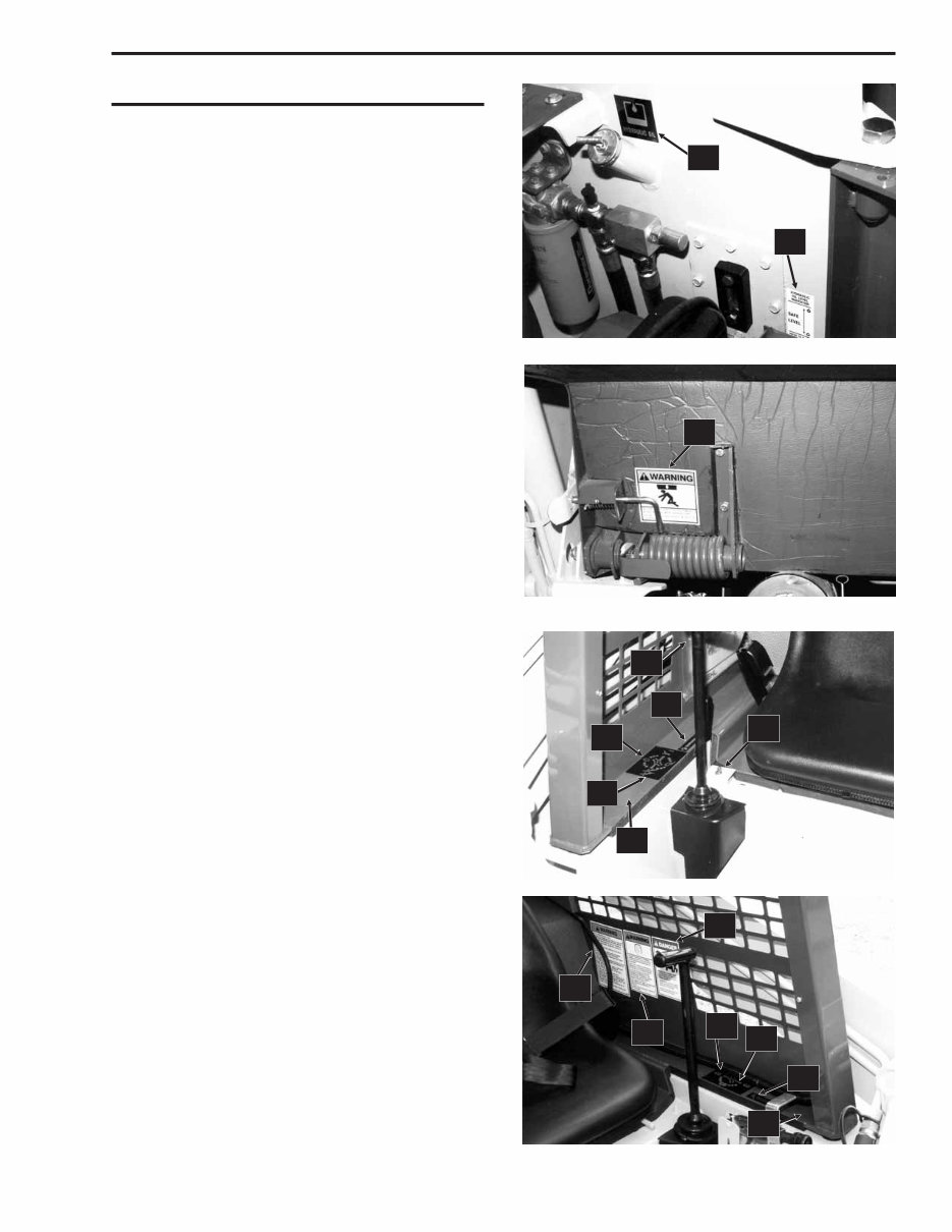
DECAL LIST Decals may be purchased individually or in kit form. This listing is repeated on each decal page for your convenience. Ref Part No. No. Description 122958 Decal Kit 1 056859 Coolant Mixture 2 067493 Red Reflector Strip 3 072794 Hydraulic Oil Symbol 4 072797 Diesel Fuel Symbol 5 072798 Coolant Under Pressure 6 072853 Lift/Tilt Lever Operation 1 7 072854 Traction Lever Operation 1 8 073075 Slow-Fast (Rabbit-Turtle) Symbol 9 073076 Brake Operation 10 073458 Non-Skid Strip 11 079362 Hydraulic Oil Level 12 088790 Auxiliary Hydraulics Operation 1 13 091033 WARNING - Jump Starting Loader 14 091035 DANGER - Lift Arm Raised 15 091050 DANGER - Rotating Component 16 093202 DANGER - Avoid Electrical Contact 17 073366 IMPORTANT- Locate Manual Here 18 093367 WARNING - Owner’s Responsibility 19 093474 WARNING-General Safety Precautions 20 093477 WARNING-Overhead Guard Safety Pin 21 093479 WARNING - Carry Load Low 22 093483 WARNING - Carry Load Low 23 093484 DANGER - Heating Unit Grounding 24 093506 Operating Capacities 25 094951 Made in U.S.A 26 121030 Non-Skid Strip 27 122289 GEHL - On Grille 28 122432 GEHL - On Liftarm Front 29 122616 GEHL - On Vertical Riser 30 122718 WARNING - Quick-Tach Locking Pin 31 123378 Forward-Reverse Lever 2 32 123379 Forward-Reverse Auxiliary Lever 2 33 123380 Lift Pedal Operation 2 34 123381 Tilt Pedal Operation 2 35 123598 Dual Pump Switch 36 123912 WARNINGS 37 127275 Model Identification (SL6625SX) 127276 Model Identification (SL6625DX) 38 129267 Service Guide 1 T-Bar Models Only 2 Hand/Foot Models Only PRINTED IN U.S.A. 4 907286/AP0199 SL6625 - DECALS 20 3 11 34 35 17 8 6 32 (not shown) 33 9 31 7 16 18 19 (not shown)
Gehl 6625 Skid Loader Parts Manual is a comprehensive electronic guide providing essential information for vehicle repair and maintenance. It is a valuable resource for both professional technicians and DIY enthusiasts, offering detailed insights into the diagnosis and repair of the vehicle.
This high-quality manual is complete and intact, ensuring there are no missing or corrupt pages or sections. It serves as a convenient reference book, offering comprehensive explanations of installation, removal, disassembly, assembly, repair, and check procedures in a sequential order.
The manual covers Gehl 6625 Skid Loader models with serial number 7605 and later, including main loader components, hydraulic components, attachments, and more. It is available in PDF format, compatible with all versions of Windows and Mac operating systems. The language of the manual is English, and it requires Adobe Reader and WinZip for access.
With the Gehl 6625 Skid Loader Parts Manual, users can effectively maintain and repair their vehicles, ensuring optimal performance and cost-effective solutions.