VOLVO G990 MOTOR GRADER Workshop Service Repair Manual
What's Included?
Lifetime Access
Fast Download Speeds
Offline Viewing
Access Contents & Bookmarks
Full Search Facility
Print one or all pages of your manual
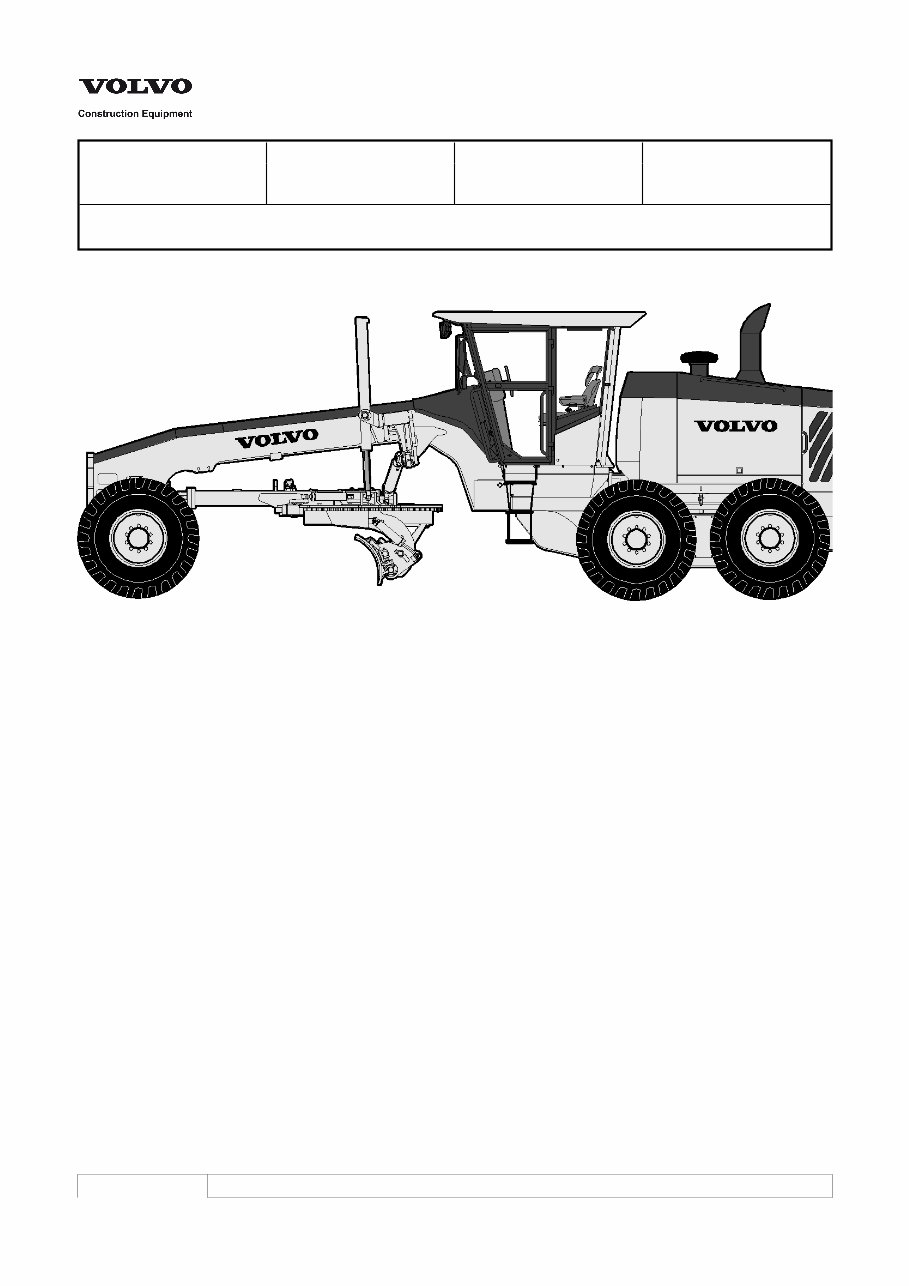
Service Information Document Title: Function Group: Information Type: Date: Description, complete machine 000 Service Information 2014/12/8 Profile: GRD, G990 [GB] Description, complete machine Figure 1 G900 General, side view Intended use The machine is intended to be used under normal conditions for the operations described in the Operator’s Manual. If it is used for other purposes or in potentially dangerous environments, for example, an explosive atmosphere, areas with dust containing asbestos, etc., special safety regulations must be followed and the machine must be equipped for such use. Contact the manufacturer / dealer for further information. Engine G930, G940, G946, G960 G930 Volvo D7EGCE3, G940 Volvo D7EGBE3, G946 and G960 Volvo D7EGAE3. A 7.2 litre (439 in3) six cylinder, four stroke, direct-injection, low-emission engine which is turbocharged with charge air cooling of the air to air type. Common rail fuel system and IEGR (internal exhaust gas recirculation) are controlled by the engine electronic control unit (E-ECU) software. The engine has wet, replaceable cylinder liners and two valves per cylinder with replaceable valve guides and valve seat inserts. The accelerator position is transferred electrically from the accelerator pedal to the control unit (E-ECU). All models have VHP (Variable horsepower). G970, G976, G990 G970 Volvo D9BGAE3, G976 and G990 Volvo D9BGBE3. A 9.4 litre (574 in3) six cylinder, four stroke, direct-injection, low- emission engine which is turbocharged with charge air cooling of the air to air type. Overhead camshaft and unit injectors and IEGR (internal exhaust gas recirculation) are controlled by the engine electronic control unit (E-ECU) software. The engine has wet, replaceable cylinder liners and two valves per cylinder with replaceable valve guides and valve seat inserts. The accelerator position is transferred electrically from the accelerator pedal to the control unit (E-ECU). All models have VHP (Variable horsepower). VHP All Volvo grader models have engines that provide three different power levels depending on the gear selected by the operator. Transmission gear VHP engine power
range HTE840 HTE1160 Low F1, F2, R1 F1, F2, F3, R1, R2 Mid F3, F4, F5, R2, R3 F4, F5, F6, F7, R3, R4 High F6, F7, F8, R4 F8, F9, F10, F11, R5, R6 Electrical system The electrical system is a 24VDC, negative-ground system. Power is supplied by two 12VDC batteries connected in series. Battery charging is accomplished using a standard 80 amp alternator or an optional 100 amp alternator. Electrical power can be isolated using a battery disconnect switch. The machine has three electronic control units (ECUs). The I-ECU for the instrumentation is integrated with the display unit, warning lamps and instruments, and provides the operator with information via these. The V-ECU (for the machine) receives signals from sensors on the machine and these are passed on to the I-ECU and E-ECU. The V-ECU is placed in the electrical distribution box on the back wall of the cab. The E-ECU controls the engine. For D7 engines, the E-ECU is installed in the cooling module. For D9 engines, the E-ECU is installed on the engine. Power transmission All machine models are equipped with the standard HTE840 powershift transmission, which has 8 forward and 4 reverse speeds. All machine models can be equipped with the optional HTE1160 powershift transmission, which has 11 forward and 6 reverse speeds. Both transmissions are direct drive, fully sequential units using a countershaft design. Rear axle / tandems Models G930, G940, G946 and G960 are equipped with the APR70 rear axle. Models G970, G976 and G990 are equipped with the APR90 rear axle. Each has an operator-controlled lock / unlock differential. Tandem wheels are chain-driven. Brake system Hydraulically actuated, oil disc service brakes are located at the four tandem drive wheels. The crossover dual braking circuits provide even braking on both sides of the machine. If the engine stalls or hydraulic boost pressure becomes unavailable, full braking capability is available through a reserve system. An electric motor and hydraulic pump unit supplies the power required to bring the machine to a safe stop. Parking brake The parking brake is a spring applied / hydraulically released, wet multiple disc brake. The brake assembly is installed inside the rear axle housing. In the event of transmission system pressure loss, an accumulator in the circuit stores system pressure and allows the parking brake to remain released for about 20 minutes. Steering system The steering system is a closed-centre, dynamic signal, load sensing system. The hydraulic steering system incorporates two steering cylinders and the turning arc is 50°. The leaning wheel and articulating frame features can be used to decrease the turning radius. Secondary steering is available as an option. Cab and frame Enclosed cabs can be provided with pressurized air conditioning and / or heating systems as options. All controls are housed in the fully adjustable steering pedestal and the right-hand side console. Ergonomic seating and hydraulic control lever placement ensure operator comfort and efficiency. The frame articulates 23° (models G930 to G960), 21° (models G970 to G990) to the left or to the right and uses lock valves to ensure stable operation. FOPS and ROPS The cab is approved as a protective cab according to the FOPS and ROPS standards, see page 207. FOPS is an abbreviation of Falling Object Protective Structure (roof protection) and ROPS is an abbreviation of Roll Over Protective Structure (roll over protection). Never carry out any unauthorized alterations to the cab without first, through a dealer, having discussed the alteration with personnel at the Volvo CE Engineering Department. This department will decide whether the alteration may cause the ROPS approval to become void. Hydraulic system The closed-centre hydraulic system uses a pressure and flow compensated (load sensing) variable displacement piston pump. The pump supplies oil to the implements and the steering. The cooling fan is driven by a hydraulic motor. Fan speed is variable and is determined by various cooling requirements. The fan operates between pre-determined minimum and maximum speeds. The fan remains at its minimum speed until there is a demand for cooling. Fan speed will automatically increase with the demand for cooling. Lock valves are incorporated in the blade lift, moldboard tilt, circle shift, wheel lean and articulation hydraulic circuits to prevent cylinder drift. The control levers are short throw, feathering type located on a fully adjustable steering pedestal.
All Wheel Drive G946 and G976 are All Wheel Drive (AWD) models. The AWD system is powered by two electronically controlled, variable displacement hydraulic pumps in separate closed loop systems. Each pump supplies one front wheel motor. Front wheel motors are two-speed, high torque, radial piston, cam lobe type. Each wheel motor has a separate speed sensor. Equipment and attachments The circle, drawbar and moldboard equipment is fully manoeuvrable using hydraulic cylinders. Blade mobility permits steep ditch cutting angles and back sloping outside of overall machine width. The circle is held in place by adjustable clamp plates and guide shoes. Bearing surfaces are faced with ‘Duramide™’ for maximum service life. Hardened teeth are cut on the outside of the circle. The moldboard is provided with a replaceable cutting edge and end bits. The drawbar is a narrow “T” design for optimum visibility to the work area. Five common attachments include: Mid-mounted scarifier Front-mounted scarifier Rear-mounted ripper Front-mounted dozer blade Front-mounted push block Modifications Modifications to this machine including the use of unauthorized attachments, accessories, assemblies or parts may affect the integrity of the machine and/or the ability of the machine to perform as designed. Persons or organizations making unapproved modifications assume all liability arising from or related to the modification, including any adverse affect on the machine. No modifications of any kind should be made to this product unless the specific modification has been officially approved in writing by Volvo Construction Equipment. Volvo Construction Equipment reserves the right to reject any and all warranty claims which arise from or are related to unauthorized modifications. Modifications are officially approved if at least one of the following conditions is met: 1. 2. The attachment, accessory, assembly or part is manufactured or distributed by Volvo Construction Equipment and installed in a factory approved manner as described in the publications available from Volvo Construction Equipment; or The modification has been approved in writing by the Product Line Engineering Department of Volvo Construction Equipment.
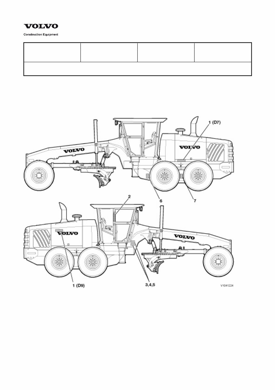
Service Information Document Title: Function Group: Information Type: Date: Product identification plates 000 Service Information 2014/12/8 Profile: GRD, G990 [GB] Product identification plates With the aid of the product plates, shown below, it is possible to identify the machine and its components. The Product Identification Number, PIN, indicates the model designation, engine code and serial number of the machine. The Component Identification Number, CIN, indicates the serial number of the component. When ordering spare parts, and in all telephone enquiries or correspondence, the PIN and CIN must always be quoted. Figure 1 Product identification plates 1 Engine The engine model designation, serial number and power rating (plate attached on the engine). 2 Cab ROPS / FOPS number and ROPS / FOPS certificate number (plate attached on the R.H. door post). 3 Product plate The manufacturer’s name and address, machine model 5 Product plate for TUV (Germany) Machine model designation, PIN, max. machine weight, max. charge weight on front axle, max. charge weight on rear axle, year of manufacture. 6 Transmission The manufacturer’s name and address and transmission CIN (plate attached to the housing). 7 Rear axle
designation, machine PIN, machine weight, engine output, year of manufacture, year of delivery and position of CE mark (EU / EEA countries only). 4 CE mark Separate self-adhesive decal attached to the product plate (EU / EAA countries only). The manufacturer’s name and address and rear axle CIN (plate attached to the housing).
The VOLVO G990 MOTOR GRADER Workshop Service Repair Manual is an essential resource for professional technicians and do-it-yourself mechanics alike. This comprehensive manual provides in-depth guidance for repairing and maintaining the VOLVO G990 MOTOR GRADER, covering all styles and models.
With easy-to-read text sections, high-quality diagrams, and step-by-step instructions, this manual equips both novice and experienced mechanics with the knowledge to efficiently perform repairs. It covers critical specifications, disassembly, assembly, cleaning, and reinstalling procedures, among other essential maintenance tasks.
Whether you opt for a paper manual or the digital version, you'll have access to the same features, including detailed repair procedures, illustrations, and specifications. The digital version offers the added convenience of instant access without any shipping fees, allowing you to address maintenance and repair needs promptly.
The VOLVO G990 MOTOR GRADER Workshop Service Repair Manual is available in English and can be easily accessed on various operating systems. It is delivered in a file format that allows for easy printing and zooming in and out for detailed viewing.
What sets this manual apart is its instant delivery upon purchase, eliminating the need for additional software or waiting time. It provides comprehensive information on general maintenance, care, safety, engine, power transmission, hydraulic systems, and more, making it an indispensable resource for anyone working with the VOLVO G990 MOTOR GRADER.
VOLVO G990 MOTOR GRADER General Information
VOLVO G990 MOTOR GRADER Routine Maintenance
VOLVO G990 MOTOR GRADER Care and Safety
Body and Framework
VOLVO G990 MOTOR GRADER Standard Parts, Service
VOLVO G990 MOTOR GRADER Engine with Mounting and Equipment
VOLVO G990 MOTOR GRADER Elec. System, Warning System, Information System, Instruments
VOLVO G990 MOTOR GRADER Power Transmission
VOLVO G990 MOTOR GRADER Brake
VOLVO G990 MOTOR GRADER Steering
VOLVO G990 MOTOR GRADER Frame and Wheel
VOLVO G990 MOTOR GRADER Machinery House, Cab, Exterior Trim Parts Anywhere
VOLVO G990 MOTOR GRADER Hydraulic System
VOLVO G990 MOTOR GRADER Hydraulic and Electric schematics
Thank you for considering the VOLVO G990 MOTOR GRADER Workshop Service Repair Manual as your go-to resource for all repair and maintenance needs. It's a valuable tool that provides instant access to comprehensive information, ensuring efficient and accurate repairs for the VOLVO G990 MOTOR GRADER.
Recently Viewed
5,521,897Happy Clients
2,594,462eManuals
1,120,453Trusted Sellers
15Years in Business
Price:
Actual Price:
VOLVO G990 MOTOR GRADER Workshop Service Repair Manual