Parts Catalog Print No. S3PS00018ZE01 Issued 6 /2014 CX55B Mini Crawler Excavator ASN PS04-10001 (NETN55001) NA
GENERAL INFORMATION 1. Whenever the terms left and right are used, it should be understood to mean from a position facing in direction of travel. 2. Throughout this manual you may find common hardware not illustrated, but listed in the description column. The service part immediately preceding a hardware listing is the part using these particular items for mounting purposes. This hardware is not included with the service part or assembly when ordered as a replacement. 3. The illustrations show typical assemblies plus individual parts but in all cases may not show the exact shape or detail of parts required. However, the purpose for the illustrations is to identify parts performing like functions. Whenever possible, illustrations are located at the beginning of each section or immediately adjacent to the applicable text. 4. CNH America LLC is continually striving to improve its products. We must, therefore, reserve the right to make improvements or changes when it becomes practical and possible to do so, without incurring any obligation to make changes or additions to the equipment sold previously. CNH America LLC, Racine, WI 53404 U.S.A.
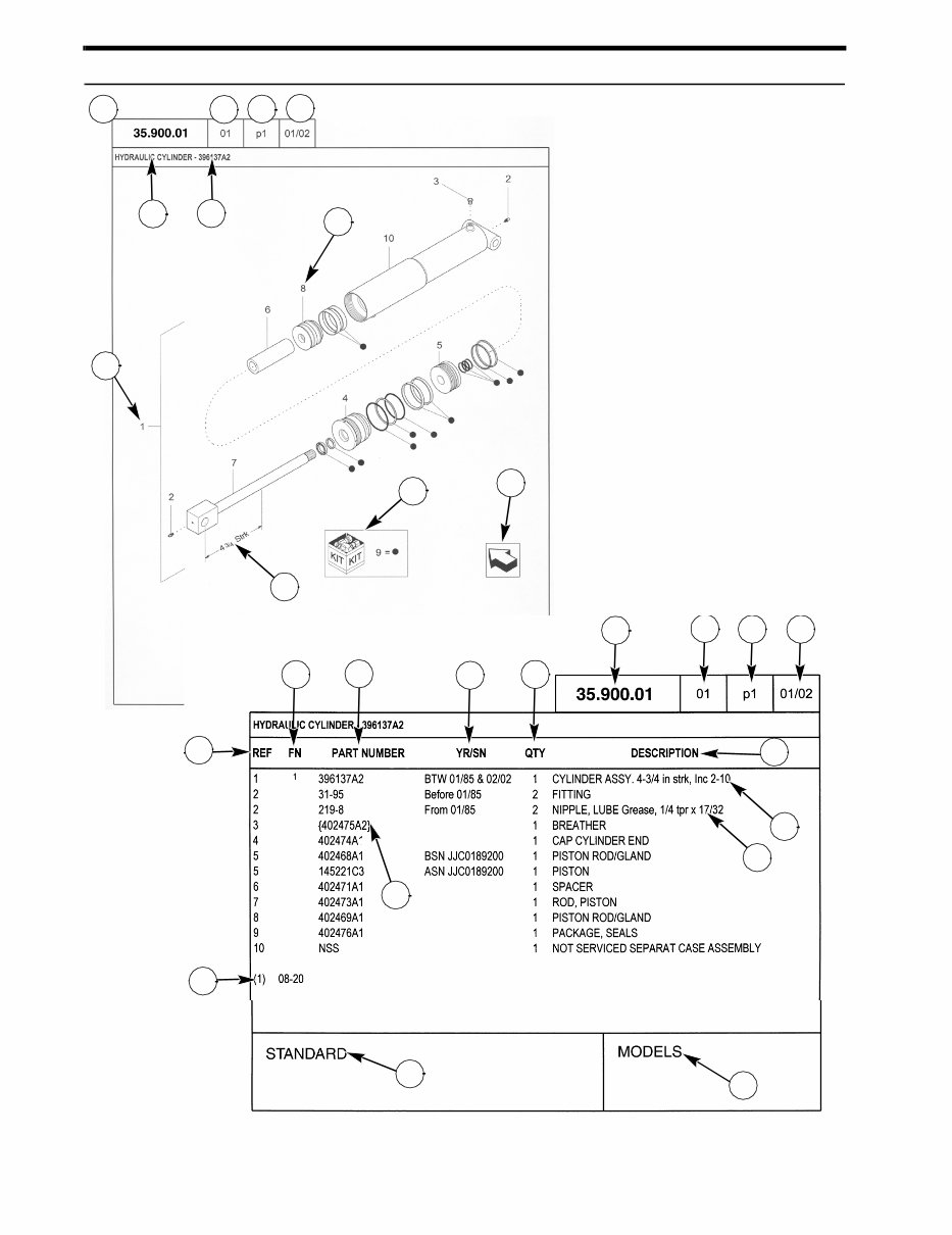
How to Use Your Parts Catalog 1 2 3 4 9 7 11 5 6 8 10 14 19 18 20 10 17 12 13 15 1 2 3 4 8 12 16
How to Use Your Parts Catalog 1. Figure Number 2. Sequence code within the Figure Number 3. Page number within the Sequence Code 4. Date of Printing (month / year) 5. Figure Description 6. General information regarding the figure 7. Parts supplied in repair kits per symbol reference 8. Figure call-out of the part number (REF) 9. Technical Specifications relating to the part indicated 10. Figure call-out includes bracketed items, the included items may also be listed in the additional description area 11. Orientation - Arrow indicates front of the machine 12. Footnote - Additional information relating to the part number. In this example, 08-20 equals another figure that this part is shown on. 13. Part Number NSS = Non-serviced parts Bracketed numbers = not available as service parts in this market 14. Not Available as service part in this market 15. YR/SN Year Before 01/85 = Part valid for production January 1985 and before From 01/85 = Part valid for production from January 1985 and after BTW 01/85 & 02/02 = Part valid for machines produced between January 1985 and February 2002. Serial Number (P.I.N.) BSN JJC0268800 = Part valid for serial number JJC0268800 and below ASN JJC0268800 = Part valid for serial number JJC0268800 and above BTW JJC0178000 & JJC0179000 = Part valid for serial numbers between JJC0178000 & JJC0179000 16. Total Quantity of the Part referred to in the page. The quantity can be replaced by the following indications: AR = quantity as required X = as required 17. Part Description 18. Additional description of the part to help confirm identification 19. Figure Notes 20. Model Number(s)
Explanation of Abbreviations Abbreviation Meaning adj adjustable amp ampere AR As required ASN Serial number and after / P.I.N. and after barb barb blkhd bulkhead boss boss BSN before serial number / before P.I.N BTW between cc cubic centimetre chain chain cl class cp pt cup point CRS Chrome Alloy Steel CST Carbon Steel cu yd cubic yard deg degree dia diameter dr type drive type dry dry fc face fc sl face seal fem female fem PT female pipe thread fl flare ft feet (or foot) gal gallon(s) gr grade hd head hp horsepower ID inside diameter in inch(es) Inc. includes inv fl inverted flare K kilo kg kilogram L litre lb pound(s) lg long LH left hand LH thd left hand thread links links M (prefix) metric thread size m metre male male mm millimetre NF National Fine No. number NS National Super Fine OD outside diameter ohm electrical unit of resis- tance Or O-ring orifice orifice P pitch piece piece psi pounds per square inch PT pipe thread rd round rd holes round holes RH right hand RH thd right hand thread rpm revolutions per minute Abbreviation Meaning
Dimensions Metric and U.S. hardware dimensions do not show the numeric designations of standard coarse threads. A number following a semi colon (;) is the class or grade of hardware. A comma (,) represents the decimal point (.) used in U.S. dimensions. sl self locking slat slat spool spool sq square SST Stainless Steel st self tapping stem stem strk stroke sw swivel T teeth Teflon Teflon thin thin thk thick tpr taper Abbreviation Meaning tube tube type type V volt(s) W watt(s) way way wide wide X as required yd yard Abbreviation Meaning Explanation of Abbreviations
TABLE OF CONTENTS 00.000.00 01 MAIN SECTIONS 00.000.05 01 PICTORIAL INDEX - MACHINE COMPLATION AND EQUIPMENT 00.000.10 01 PICTORIAL INDEX - ENGINE 00.000.10 02 PICTORIAL INDEX - ENGINE 00.000.31 01 PICTORIAL INDEX - PTO 00.000.35 01 PICTORIAL INDEX - HYDRAULIC SYSTEMS 00.000.35 02 PICTORIAL INDEX - HYDRAULIC SYSTEMS 00.000.35 03 PICTORIAL INDEX - HYDRAULIC SYSTEMS 00.000.35 04 PICTORIAL INDEX - HYDRAULIC SYSTEMS 00.000.39 01 PICTORIAL INDEX - FRAMES AND BALLASTING 00.000.48 01 PICTORIAL INDEX - TRACKS AND TRACK SUSPENSION 00.000.50 01 PICTORIAL INDEX - CAB CLIMATE CONTROL 00.000.55 01 PICTORIAL INDEX - ELECTRICAL SYSTEMS 00.000.71 01 PICTORIAL INDEX - LUBRICATION 00.000.84 01 PICTORIAL INDEX - BOOMS, DIPPERS AND BUCKETS 00.000.86 01 PICTORIAL INDEX - DOZER ASSY 00.000.88 01 PICTORIAL INDEX - ACCESSORIES 00.000.90 01 PICTORIAL INDEX - PLATFORM, CAB, BODYWORK AND DECALS 00.000.90 02 PICTORIAL INDEX - PLATFORM, CAB, BODYWORK AND DECALS 00.000.90 03 PICTORIAL INDEX - PLATFORM, CAB, BODYWORK AND DECALS 00.200.AA 01 PAINT COLOR 05.000.00 01 SECTION INDEX - MACHINE COMPLATION AND EQUIPMENT 05.100.01 01 INITIAL STOCKING LIST (ISL) LIST A 05.100.01 02 INITIAL STOCKING LIST (ISL) LIST B 05.100.03 01 FILTER LIST 05.100.03 01 FILTERS 05.100.03 02 CAPACITIES 10.000.00 01 SECTION INDEX - ENGINE 10.000.00 02 SECTION INDEX - ENGINE 10.001.AD 01 CYLINDER BLOCK 10.001.AK 01 ENGINE MOUNTING, WITH AIR CONDITIONER 10.001.AK 01 ENGINE MOUNTING, WITHOUT AIRCONDITIONER 10.001.AK 02 ENGINE MOUNTING, WITH AIR CONDITIONER 10.001.AK 02 ENGINE MOUNTING, WITHOUT AIR CONDITIONER
TABLE OF CONTENTS 10.101.99 01 CYLINDER HEAD AND BONNET 10.101.99 02 CYLINDER HEAD AND BONNET 10.102.BB 01 GEAR, HOUSING 10.103.AA 01 CRANKSHAFT AND PISTON 10.103.AK 01 FLYWHEEL HOUSING AND OIL SUMP 10.106.AG 01 CAMSHAFT AND DRIVING GEAR 10.114.AI 01 GASKET, SET 10.202.AB 01 AIR CLEANER 10.202.AB 02 AIR CLEANER 10.210.AO 01 FUEL SUPPLY PUMP 10.216.AI 01 FUEL TANK 10.216.AI 02 FUEL TANK 10.216.AI 03 FUEL TANK 10.216.BA 01 FUEL TANK LINES 10.216.BA 02 FUEL TANK LINES 10.218.AD 01 FUEL LINE 10.218.AF 01 FUEL INJECTION VALVE 10.220.AA 01 THROTTLE LINKAGE, LEVER ASSY 10.254.AC 01 EXHAUST MANIFOLD 10.254.AI 01 EXHAUST MUFFLER 10.254.AI 02 EXHAUST MUFFLER 10.254.AM 01 SUCTION MANIFOLD 10.304.AC 01 LUB OIL SYSTEM 10.400.99 01 COOLING WATER SYSTEM 10.400.99 02 COOLING WATER SYSTEM 10.400.AY 01 RADIATOR & HOSE 10.400.AY 02 RADIATOR HOSES, WITHOUT AIR CONDITIONER 10.400.BE 01 RADIATOR MOUNTING 10.400.BF 01 RADIATOR FRAME AND SUPPORTS 10.400.BF 02 RADIATOR FRAME AND SUPPORTS 10.400.BF 03 RADIATOR FRAME AND SUPPORTS 10.501.AE 01 DIESEL PARTICULATE FILTER 31.000.00 01 SECTION INDEX - PTO 31.101.AB 01 POWER TAKE-OFF (PTO) ASSY, WITH AIR CONDITIONER
TABLE OF CONTENTS 35.000.00 01 SECTION INDEX - HYDRAULIC SYSTEM 35.000.00 02 SECTION INDEX - HYDRAULIC SYSTEM 35.000.00 03 SECTION INDEX - HYDRAULIC SYSTEM 35.000.00 04 SECTION INDEX - HYDRAULIC SYSTEM 35.100.AB 01 CONTROL LINES, MAIN 35.100.AB 02 CONTROL LINES, MAIN 35.100.AB 03 CONTROL LINES, MAIN (NIBBLER AND BREAKER) 35.100.AB 04 CONTROL LINES, MAIN 35.100.AB 05 CONTROL LINES, MAIN (COOLER) 35.100.AB 06 CONTROL LINES, MAIN (ANGLE DOZER) 35.100.AB 07 CONTROL LINES, MAIN (COOLER LESS) 35.106.AD 01 HYDRAULIC PUMP ASSY, PTO WITH AIR CONDITIONER 35.106.AD 01 HYDRAULIC PUMP ASSY, PTO WITHOUT AIR CONDITIONER 35.106.AD 02 HYDRAULIC PUMP ASSY, PTO WITH AIR CONDITIONER 35.106.AD 02 HYDRAULIC PUMP ASSY, PTO WITHOUT AIR CONDITIONER 35.106.AD 03 HYDRAULIC PUMP ASSY, PTO WITH AIR CONDITIONER 35.106.AD 03 HYDRAULIC PUMP ASSY, PTO WITHOUT AIR CONDITIONER 35.106.AD 04 HYDRAULIC PUMP ASSY, PTO WITH AIR CONDITIONER 35.106.AD 04 HYDRAULIC PUMP ASSY, PTO WITHOUT AIR CONDITIONER 35.204.AA 01 CONTROL LINES, VALVE, ACCUMULATOR 35.300.AQ 01 HYDRAULIC TANK ASSY 35.300.AQ 02 HYDRAULIC TANK ASSY 35.310.AA 01 CONTROL VALVE INSTALL 35.310.AA 02 CONTROL VALVE ASSY 35.310.AA 03 CONTROL VALVE FOR BUCKET, TRAVEL LEFT 35.310.AA 04 CONTROL VALVE ASSY, BOOM 35.310.AA 05 CONTROL VALVE ASSY FOR SUPPLY, TRAVEL RIGHT, SERVICE AND BOOM SWING 35.310.AA 06 CONTROL VALVE ASSY FOR ARM, ARM CONFLUENCE (JOINING), SLEWING 35.310.AA 07 CONTROL VALVE ASSY, DOZER 35.310.AA 08 CONTROL VALVE ASSY, TRAVEL INDEPENDENCE 35.310.AA 09 CONTROL VALVE INSTALL, (ROTARY/ANGLE DOZER) 35.310.AA 10 CONTROL VALVE ASSY 35.310.AA 11 CONTROL VALVE FOR BUCKET, TRAVEL LEFT
The Case CX55B Mini Excavators Parts Catalog is an essential resource for professional mechanics and DIY enthusiasts alike. It contains detailed parts listings and easy-to-understand exploded view illustrations, making it indispensable for anyone working with the CX55B model.
This user-friendly catalog enables quick and precise location of the necessary parts for the CX55B Mini Excavator. Whether it's routine maintenance or repairs, having access to the right parts is crucial for efficient completion of the task at hand.
In addition to providing detailed parts information, the Case CX55B Mini Excavators Parts Catalog also includes helpful diagrams illustrating how each component fits together. This visual aid is invaluable for understanding the inner workings of the excavator and ensuring the correct parts are ordered.