

116 Hydraulic Excavator Service Repair Manual
What's Included?
Fast Download Speeds
Online & Offline Access
Access PDF Contents & Bookmarks
Full Search Facility
Print one or all pages of your manual

*bobcat
116
HYDRAULIC
EXCAVATOR
MELROEcoMPANY ·
.,
6570484 (4°87)·5C
A ·BUSINESS UNIT OF CLIIRK EQUIPMENT COMPANY Printed in U.S.A.

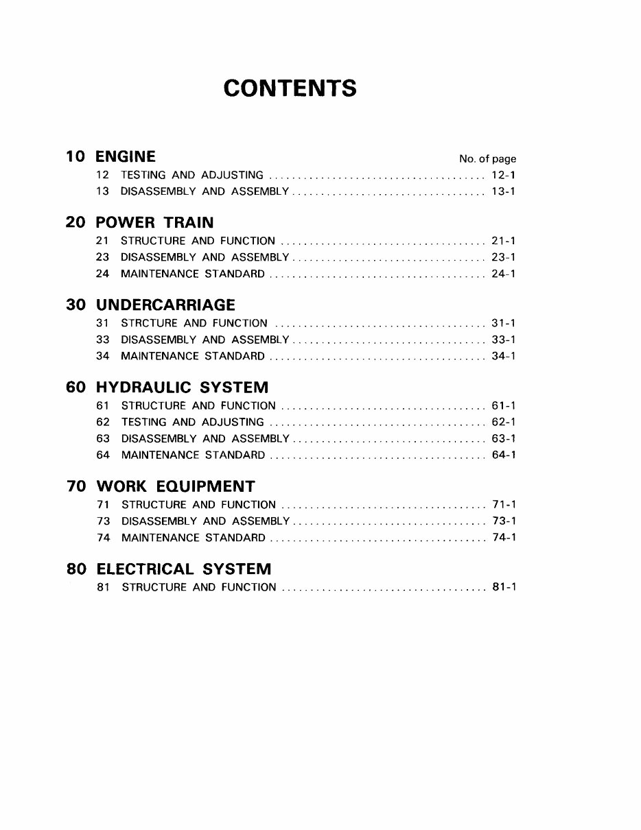
CONTENTS
10 ENGINE No. of page
12 TESTING AND ADJUSTING . . . . . . . . . . . . . . . . . . . . . . . . . . . . . . . . . . . . . 12-1
13 DISASSEMBLY AND ASSEMBLY . . . . . . . . . . . . . . . . . . . . . . . . . . . . . . . . . . 13-1
20 POWER TRAIN
21 STRUCTURE AND FUNCTION .................................... 21-1
23 DISASSEMBLY AND ASSEMBLY . . . . . . . . . . . . . . . . . . . . . . . . . . . . . . . . . . 23-1
24 MAINTENANCE STAND ARD ............................. _. . . . . . . . 24-1
30 UNDERCARRIAGE
31 STRCTURE AND FUNCTION ..................................... 31-1
33 DISASSEMBLY AND ASSEMBLY .................................. 33-1
34 MAINTENANCE STANDARD ...................................... 34-1
60 HYDRAULIC SYSTEM
61 STRUCTURE AND FUNCTION .................................... 61-1
62 TESTING AND ADJUSTING ...................................... 62-1
63 DISASSEMBLY AND ASSEMBLY .................................. 63-1
64 MAINTENANCE STANDARD . . . . . . . . . . . . . . . . . . . . . . . . . . . . . . . . . . . . . . 64-1
70 WORK EQUIPMENT
71 STRUCTURE AND FUNCTION . . . . . . . . . . . . . . . . . . . . . . . . . . . . . . . . . . . . 71 -1
73 DISASSEMBLY AND ASSEMBLY . . . . . . . . . . . . . . . . . . . . . . . . . . . . . . . . . . 73-1
7 4 MAINTENANCE STAND ARD . . . . . . . . . . . . . . . . . . . . . . . . . . . . . . . . . . . . . . 7 4-1
80 ELECTRICAL SYSTEM
81 STRUCTURE AND FUNCTION . . . . . . . . . . . . . . . . . . . . . . . . . . . . . . . . . . . . 81 -1

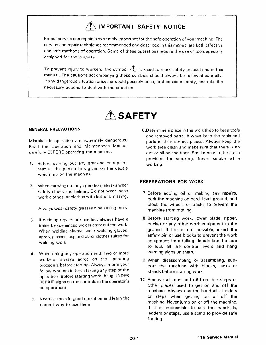
it IMPORTANT SAFETY NOTICE
Proper service and repair is extremely important for the safe operation of your machine. The
service and repair techniques recommended and described in this manual are both effective
and safe methods of operation. Some of these operations require the use of tools specially
designed for the purpose.
To prevent injury to workers, the symbol ffi is used to mark safety precautions in this
manual. The cautions accompanying these symbols should always be followed carefully.
If any dangerous situation arises or could possibly arise, first consider safety, and take the
necessary actions to deal with the situation.
it SAFETY
GENERAL PRECAUTIONS
Mistakes in operation are extremely dangerous.
Read the Operation and Maintenance Manual
carefully BEFORE operating the machine.
1. Before carying out any greasing or repairs,
read all the precautions given on the decals
which are on the machine.
2. When carrying out any operation, always wear
safety shoes and helmet. Do not wear loose
work clothes, or clothes with buttons missing.
Always wear safety glasses when using tools.
3. If welding repairs are needed, always have a
trained, experienced welder carry out the work.
When welding always wear welding gloves,
apron, glasses, cap and other clothes suited for
welding work.
4. When doing any operation with two or more
workers, always agree on the operating
procedure before starting. Always inform your
fellow workers before starting any step of the
operation. Before starting work, hang UNDER
REPAIR signs on the controls in the operator's
compartment.
5. Keep all tools in good condition and learn the
correct way to use them.
00-1
6.Determine a place in the workshop to keep tools
and removed parts. Always keep the tools and
parts in their correct places. Always keep the
work area clean and make sure that there is no
dirt or oil on the floor. Smoke only in the areas
provided for smoking. Never smoke while
working.
PREPARATIONS FOR WORK
7. Before adding oil or making any repairs,
park the machine on hard, level ground, and
block the wheels or tracks to prevent the
machine from moving.
8. Before starting work, lower blade, ripper,
bucket or any other work equipment to the
ground. If this is not possible, insert the
safety pin or use blocks to prevent the work
equipment from falling. In addition, be sure
to lock all the controi levers and hang
warning signs on them.
9. When disassembling or assembling, sup-
port the machine with blocks, jacks or
stands before starting work.
10. Remove all mud and oil from the steps or
other places used to get on and off the
machine. Always use the handrails, ladders
or steps when getting on or off the
machine. Never jump on or off the machine.
If it is impossible to use the handrails,
ladders or steps, use a stand to provide safe
footing.
116 Service Manual
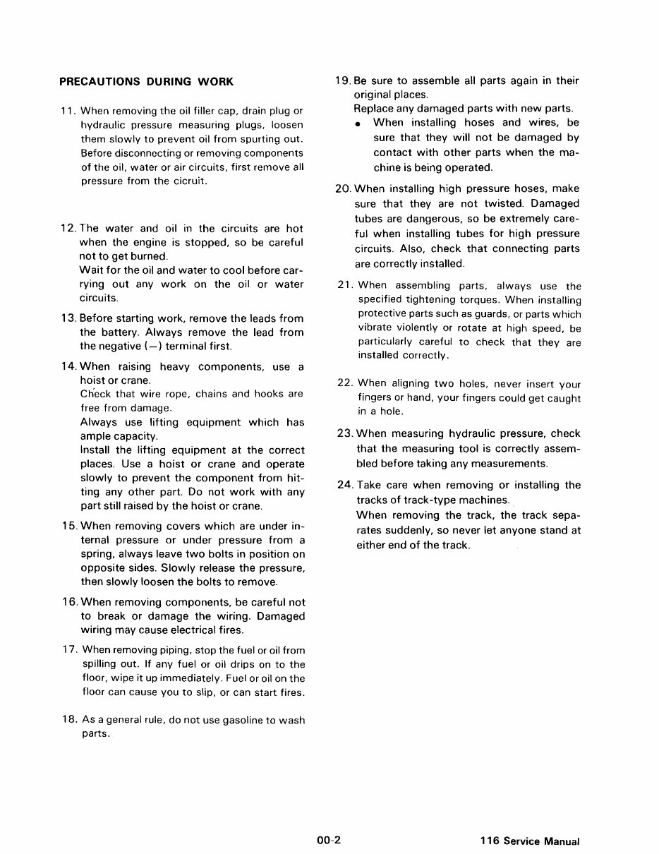
PRECAUTIONS DURING WORK
11. When removing the oil filler cap, drain plug or
hydraulic pressure measuring plugs, loosen
them slowly to prevent oil from spurting out.
Before disconnecting or removing components
of the oil, water or air circuits, first remove all
pressure from the cicruit.
12. The water and oil in the circuits are hot
when the engine is stopped, so be careful
not to get burned.
Wait for the oil and water to cool before car-
rying out any work on the oil or water
circuits.
13. Before starting work, remove the leads from
the battery. Always remove the lead from
the negative(-) terminal first.
14. When raising heavy components, use a
hoist or crane.
Check that wire rope, chains and hooks are
free from damage.
Always use lifting equipment which has
ample capacity.
Install the lifting equipment at the correct
places. Use a hoist or crane and operate
slowly to prevent the component from hit-
ting any other part. Do not work with any
part still raised by the hoist or crane.
15. When removing covers which are under in-
ternal pressure or under pressure from a
spring, always leave two bolts in position on
opposite sides. Slowly release the pressure,
then slowly loosen the bolts to remove.
16. When removing components, be careful not
to break or damage the wiring. Damaged
wiring may cause electrical fires.
1 7. When removing piping, stop the fuel or oil from
spilling out. If any fuel or oil drips on to the
floor, wipe it up immediately. Fuel or oil on the
floor can cause you to slip, or can start fires.
18. As a general rule, do not use gasoline to wash
parts.
19. Be sure to assemble all parts again in their
original places.
Replace any damaged parts with new parts.
• When installing hoses and wires, be
sure that they will not be damaged by
contact with other parts when the ma-
chine is being operated.
20. When installing high pressure hoses, make
sure that they are not twisted. Damaged
tubes are dangerous, so be extremely care-
ful when installing tubes for high pressure
circuits. Also, check that connecting parts
are correctly installed.
21. When assembling parts, always use the
specified tightening torques. When installing
protective parts such as guards, or parts which
vibrate violently or rotate at high speed, be
particularly careful to check that they are
installed correctly.
22. When aligning two holes, never insert your
fingers or hand, your fingers could get caught
in a hole.
23. When measuring hydraulic pressure, check
that the measuring tool is correctly assem-
bled before taking any measurements.
24. Take care when removing or installing the
tracks of track-type machines.
00-2
When removing the track, the track sepa-
rates suddenly, so never let anyone stand at
either end of the track.
116 Service Manual
)
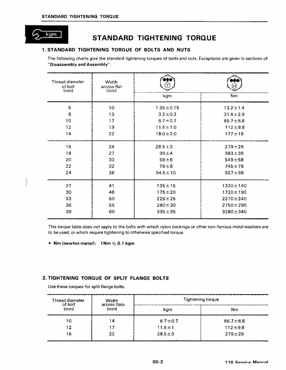
STANDARD TIGHTENING TORQUE
STANDARD TIGHTENING TORQUE
1. STANDARD TIGHTENING TORQUE OF BOLTS AND NUTS
The following charts give the standard tightening torques of bolts and nuts. Exceptions are given in sections of
"Disassembly and Assembly".
Thread diameter Width
Ci) Ci)
of bolt across flat
(mm) (mm)
kgm Nm
6 10 1.35±0.15 13.2±1.4
8 13 3.2±0.3 31.4±2.9
10 17 6.7±0.7 65.7±6.8
12 19 11.5± 1.0 112±9.8
14 22 18.0±2.0 177±19
16 24 28.5±3 279±29
18 27 39±4 383±39
20 30 56±6 549±58
22 32 76±8 745±78
24 36 94.5± 10 927±98
27 41 135 ± 15 1320±140
30 46 175±20 1720±190
33 50 225±25 2210±240
36 55 280±30 2750±290
39 60 335±35 3280±340
This torque table does not apply to the bolts with which nylon packings or other non-ferrous metal washers are
to be used, or which require tightening to otherwise specified torque.
* Nm (newton meter): 1 Nm ::::; 0.1 kgm
2. TIGHTENING TORQUE OF SPLIT FLANGE BOLTS
Use these torques for split flange bolts.
Thread diameter Width
of bolt across flats
(mm) (mm)
kgm
10 14 6.7±0.7
12 17 11.5± 1
16 22 28.5±3
00-3
Tightening torque
Nm
65.7±6.8
112±9.8
279±29
11 Si:.rvil'A M<>n• ,,.1
STANDARD TIGHTENING TORQUE
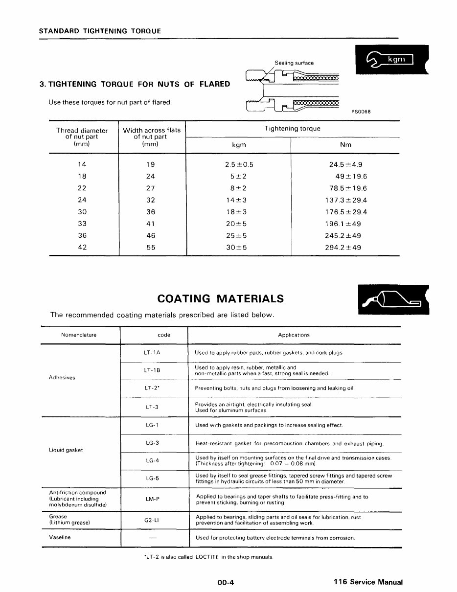
3. TIGHTENING TORQUE FOR NUTS OF FLARED
Use these torques for nut part of flared.
FS0068
Thread diameter Width across flats
Tightening torque
of nut part of nut part
(mm) (mm)
kgm Nm
14 19 2.5 ±0.5 24.5±4.9
18 24 5±2 49± 19.6
22 27 8±2 78.5 ± 19.6
24 32 14±3 137.3±29.4
30 36 18±3 176.5±29.4
33 41 20±5 196.1±49
36 46 25 5 245.2±49
42 55 30±5 294.2±49
COATING MATERIALS
The recommended coating materials prescribed are listed below.
Nomenclature code Applications
LT-1A Used to apply rubber pads, rubber gaskets, and cork plugs.
LT-1 B
Used to apply resin, rubber, metallic and
Adhesives
non-metallic parts when a fast, strong seal is needed.
LT-2" Preventing bolts, nuts and plugs from loosening and leaking oil.
LT-3
Provides an airtight, electrically insulating seal.
Used for aluminum surfaces
LG-1 Used with gaskets and packings to increase sealing effect.
LG-3 Heat-resistant gasket for precombustion chambers and exhaust piping.
Liquid gasket
LG-4
Used by itself on mounting surfaces on the final drive and transmission cases
(Thickness after tightening: 0.07 - 0.08 mm)
LG-5
Used by itself to seal grease fittings, tapered screw fittings and tapered screw
fittings in hydraulic circuits of less than 50 mm in diameter.
Antitr1ction compound
Applied to bearings and taper shafts to facilitate press-fitting and to
(Lubricant including LM-P
molybdenum disulfide)
prevent sticking, burning or rusting.
Grease
G2-LI
Applied to bearings, sliding parts and oil seals for lubrication, rust
(Lithium grease) prevention and facilitation of assembling work
Vaseline - Used for protecting battery electrode terminals from corrosion.
'L T-2 is also called LOCTITE in the shop manuals
00-4 116 Service Manual
ELECTRIC WIRE CODE
ELECTRIC
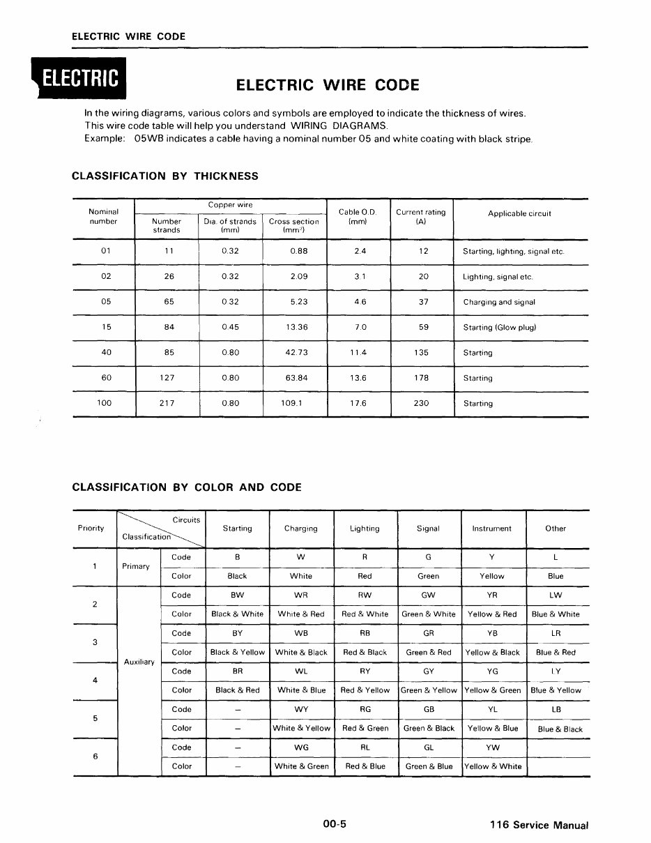
ELECTRIC WIRE CODE
In the wiring diagrams, various colors and symbols are employed to indicate the thickness of wires.
This wire code table will help you understand WIRING DIAGRAMS.
Example: 05WB indicates a cable having a nominal number 05 and white coating with black stripe.
CLASSIFICATION BY THICKNESS
Nominal
Copper wire
Cable O.D. Current rating
Applicable circuit
number Number Dia. of strands Cross section (mm) (A)
strands (mm) (mm~)
01 11 0.32 0.88 2.4 12 Starting, lighting, signal etc.
02 26 0.32 2.09 3.1 20 Lighting, signal etc.
05 65 0.32 5.23 4.6 37 Charging and signal
15 84 0.45 13 36 7.0 59 Starting (Glow plug)
40 85 0.80 42.73 11.4 135 Starting
60 127 0.80 63.84 13.6 178 Starting
100 217 0.80 109.1 17 6 230 Starting
CLASSIFICATION BY COLOR AND CODE
Priority Starting Charging Lighting Signal Instrument Other
n
Code B w R G
y
L
1 Primary
Color Black White Red Green Yellow Blue
Code BW WR RW GW YR LW
2
Color Black & White White & Red Red & White Green & White Yellow & Red Blue & White
Code BY WB RB GR YB LR
3
Color Black & Yellow White & Black Red & Black Green & Red Yellow & Black Blue & Red
Auxiliary
Code BR WL RY GY YG LY
4
Color Black & Red White & Blue Red & Yellow Green & Yellow Yellow & Green Blue & Yellow
Code WY RG GB YL LB
5
Color - White & Yellow Red & Green Green & Black Yellow & Blue Blue & Black
Code - WG RL GL YW
6
Color White & Green Red & Blue Green & Blue Yellow & White
00-5
116 Service Manual
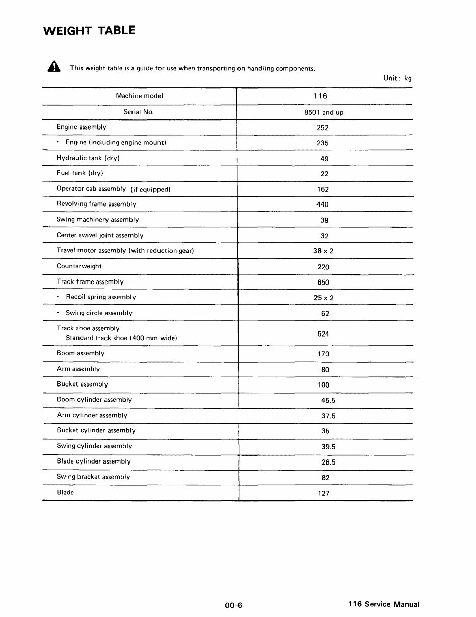
WEIGHT TABLE
A This weight table is a guide for use when transporting on handling components.
Unit: kg
Machine model 116
Serial No. 8501 and up
Engine assembly
252
Engine (including engine mount)
235
Hydraulic tank (dry)
49
Fuel tank (dry)
22
Operator cab assembly (if equipped) 162
Revolving frame assembly
440
Swing machinery assembly
38
Center swivel joint assembly
32
Travel motor assembly (with reduction gear) 38 X 2
Counterweight
220
Track frame assembly 650
Recoil spring assembly
25 X 2
.
Swing circle assembly
62
Track shoe assembly
524
Standard track shoe (400 mm wide)
Boom assembly
170
Arm assembly
80
Bucket assembly
100
Boom cylinder assembly
45.5
Arm cylinder assembly
37.5
Bucket cylinder assembly
35
Swing cylinder assembly
39.5
Blade cylinder assembly
26.5
Swing bracket assembly
82
Blade
127
00-6
116 Service Manual
You're Reading a Preview
What's Included?
Fast Download Speeds
Online & Offline Access
Access PDF Contents & Bookmarks
Full Search Facility
Print one or all pages of your manual
$52.99
Viewed 35 Times Today


Secure transaction
What's Included?
Fast Download Speeds
Online & Offline Access
Access PDF Contents & Bookmarks
Full Search Facility
Print one or all pages of your manual
$52.99
The 116 Excavator Service Manual provides detailed instructions on disassembly, repair, and reassembly of the tractor. This manual is originally intended for the dealer's service department and contains valuable information on specifications, torque, and more in a mechanic's language. Whether you are a professional mechanic or a DIY enthusiast conducting significant repairs or restoration, the Bobcat 116 Excavator Service Manual is an essential resource. It offers efficient shortcuts that can save you time and effort.


