

Case 450 Crawler Backhoe Loader Tractor OEM Service & Repair Manual
What's Included?
Fast Download Speeds
Online & Offline Access
Access PDF Contents & Bookmarks
Full Search Facility
Print one or all pages of your manual

Case 450
Crawler Backhoe
Loader Tractor
Service Maintenance
Manual
v 7.0
http://BestManuals.net
Best.Manuals@yahoo.com
© 2009, 2010 BestManuals/UserFriendlyCDs
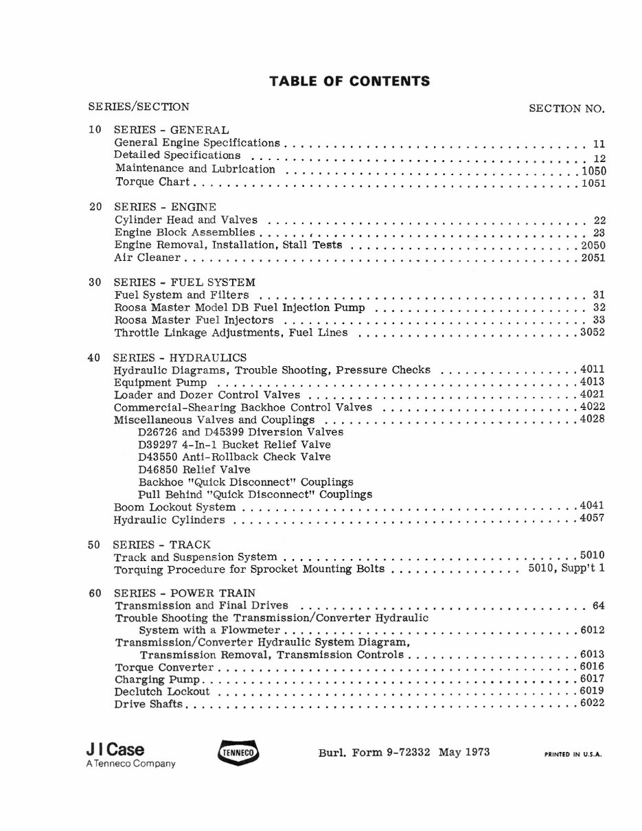
TABLE OF CONTENTS
SERIES/SECTION SECTION NO .
10 SERIES . GENERAL
General Engine Specifications ..................................... 11
Detailed Sp*ificatiws ......................................... 12
Maintenance and Lubrication ................................... -1050
Torque Chart ............................................... 1051
20 SERIES . ENGINE
Cylinder Head and Valves ....................................... 22
Engine Block Assemblies ........................................ 23
Engine Removal. Installation. Stall Tests ............................ 2050
Air Cleaner ................................................ 2051
30 SEMES- FUELSYSTEM
Fuel System and Filters ........................................ 31
.......................... Eoosa Master Model DB Fuel Injection Pump 32
..................................... Roosa Master Fuel Injectors 33
Throttle Linkage Adjustments. Fuel Lines ........................... 3052
40 SERIES . HYDRAULICS
................. Hydraulic Diagrams. Trouble Shooting. Pressure Checks
4011
EquipmentPump ............................................ 4013
................................. Loader and Dozer Control Valves 4021
Commercial-Shearing Backhoe Control Valves ........................ 4022
............................... Miscellaneous Valves and Couplings 4028
D26726 and D45399 Diversion Valves
D39297 4-111-1 Bucket Relief Valve
D43 550 Anti-Rollback Check Valve
D46850 Relief Valve
Backhoe "Quick Disc~nnect~~ Couplings
Pull Behind "Quick Disconnectw Couplings
......................................... Boom Lockout System 4041
.......................................... Hydraulic Cylinders 4057
50 SERIES . TRACK
....................................
Track and Suspension System 5010
................
Torquing Procedure for Sprocket Mounting Bolts
5010. Supp't 1
60 SEMES . POWER TRAIN
................................... Transmission and Final Drives 64
Trouble Shooting the ~ransmission/Converter Hydraulic
.................................... System with a Flowmeter 6012
~ransmission/~onverter Hydraulic System Diagram.
Transmission Removal. Transmission Controls .................... -6013
............................................ Torque Converter 6016
.............................................. Charging Pump 6017
............................................ Declutch Lockout 6019
................................................ Drive Shafts 6022
J I Case TENNEco
ATenneco Company 0
Burl . Form 9-72332 May 1973 PRINTED IN U.S.A.
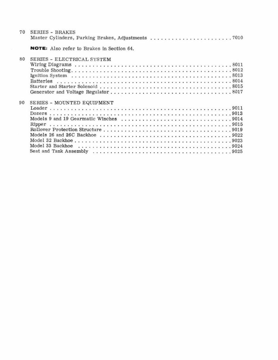
70 SERIES - BRAKES
Master Cylinders, Parking Brakes , Adjustments •.. •• .•.•... •••• .... •.. 7010
NOTIE: Also refer to Brakes in Section 64.
80 SERIES - ELECTRICAL SYSTE M
\Vlrlng DIagrams ... .. ... ..... .. ••••• ... . .. • •.. . ... .. .•••.. .. 80 11
Trouble Shooting .............. .•.•.. ..•. ..... • •• • .... •• •• .... 8012
Ign ition System .. .... .. ....... . ••••• ....... ••• ... .... ••• .... 8013
Batteries .............. ...... .• ••... . .. . .•• ..... .... •• .... 8014
Starter and Starter Solenoid . ......... ••... ... ..•. .. . ...... • . .... 8015
Generator a nd Voltage Regulator .. .. .. .. ••• ...... ••• ....... ••• .... 8017
90 SERIES - MOUNTED EQUIPMEN T
Loader ........ ... ............. •• • ....... ...• ... ..... •. ... 9011
Dozers .. .... .. ... ...... .. . .. ... .• ••••. .. . .• •• ..... ••• .... 9013
Models 9 and 19 Gearmatic Winches ...... ••• ........ •• ... .. .. •.. .. 9014
Ripper .. .. . .. .... . ... .... ...... •••• .. ... . .••. ...... • •. .. . 9015
Rollover Protection Structure . ....... • .•• . •• ..•.. . .•••• .... . •.. .. 9019
Models 26 a nd 26C Backhoe .. ... . .. .. .. .. •• . ..... ••• ••... ..•.. .. 9022
Model 32 Backhoe . . ... .......... . ..• •• .. .... ..••.. .. .. .. • .... 9023
Model 33 Backhoe .. . ... ..... .. .. .... .. • ..... .. . ••... . ..• .... 9024
Seat and T ank Assembly ..... .. . .. ..... •• ........ •• ... .. ..• .... 9025
Section
11
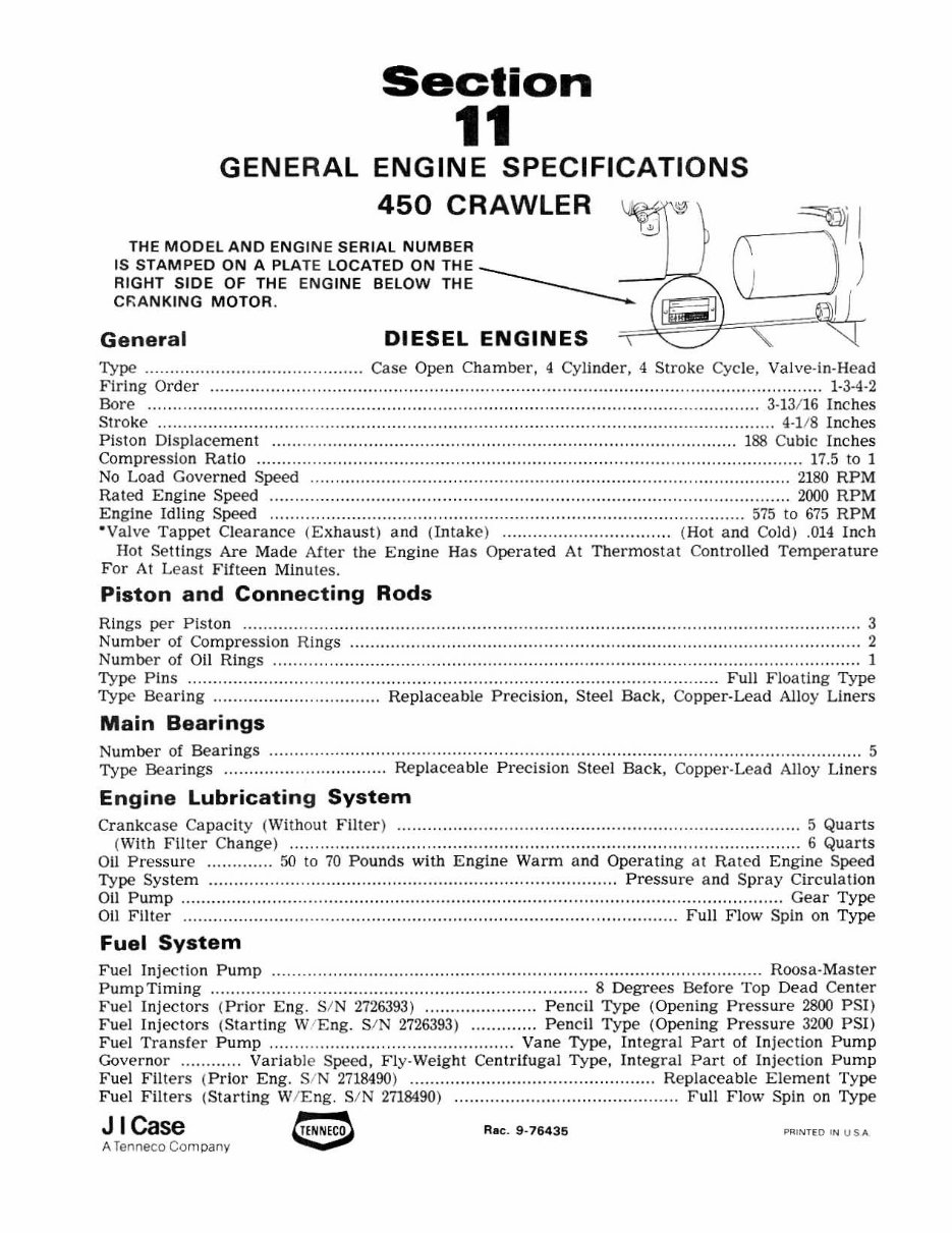
GENERAL ENGINE SPECIFICATIONS
450 CRAWLER ~. I
THE MODEl AND ENGINE SERIAL NUMBER 0
1
)
IS STAMPED ON A PLATE LOCATED ON THE _______ _
RIGHT SIDE OF THE EN GINE BELOW THE _____ - -'l-'
C~A NKING MOTOR . =~[{;~H~?JI=",==, ~I J
Ge neral DIESEL ENGINES "i .~
Type .... .. .. ........................ ..... .... Case Open Chamber, 4 Cylinder, 4 Stroke Cycle, Valv e- in-Hea d
Firing Order ............................................................ .. ....... ................................................... 1- 3-4-2
Bore .... ................................. ................. ................. .. ....... ............... ................ .. ....... 3· 13/ 16 Inches
Stroke ................................................................................. .................... .. .................. 4·]/8 Inches
P iston Displacement .............. .. ......................... ................................ .................. 1 88 Cubic Inches
Compres sion Ratio ........... ........................ ................ ............ ........... ................................. 17.5 to 1
No Load Governed Speed .......... ................ ......................... ..................... .. .................. .. 2180 RPM
Rated Engine Speed ...................................................................................................... 2000 RPM
Engine Idling Speed ....... .. ......................... ........ ...................... ......... .................... 575 to 675 RPM
· Valve Tappet Clearance (E xhaus t) and (Intake) ................................. (Hot and COld ) . 014 I nch
Hot Settings Are Made After the Engine Has Operated At Thermosta t Controlled Temperature
For At Least Fifteen Minutes.
Piston and Connecting Rods
Rings per Piston ..................... .. ... ......................................................... ........................... ...... ..... 3
Number of Compression Rings ............................... .......... ......................... ........................ .......... 2
Number of Oil Rings .......... ...................................................................... ................................ .. . 1
Type Pins .......................... ..................... ................................. .............. .......... Full Floating Type
Type Bearing .................. ............... Re placeable Precis ion, Steel Bac k, Co pper· Lead Alloy Liners
Main Bearings
Number of Bearings .......................... ................ .......... .............. ............. ..................................... 5
Type Bearings ................................ Replaceable Preci sion Steel Back , Copper·Lead Alloy Liners
En gine Lubricatin g System
Crankcase Ca pacity (Without Filt er) ......... ................... ................ .......... ......................... 5 Quarts
(With Filt er Change) ...... .. ................. .. .. ................................................................. ...... 6 Quarts
011 Pressure ............. 50 to 70 Pounds wi th Engine Warm and Operating at Rated Engine Speed
Type System ........................................................... . ....... . .. .......... Pressu re a nd Spray Circul ation
011 Pump ........................ .. .................................. ...................... ..... ............................... Gear Type
Oil Filter ................................................................... .............................. Full Flow Spin on T ype
Fuel System
Fuel Injection Pump ............................................................................................... Roosa·Mas ter
Pump Timing ........................................ .. ................................ 8 Degrees Before Top Dead Cenler
Fuel Injectors ( Prior Eng. SIN 2726393) " .................... Pencil Type (Opening Press ure 2800 PSI )
Fuel Inj ectors (St arti ng Wi Eng. SIN 2726393 ) ............. Pen c il Type (Opening Pressure 3200 PSI)
Fuel Tra ns fer Pump .. .... .. ............ ........... ................. Vane Type, In tegra l Part of Injection Pu mp
Governor ............ Variab le Speed, Fly·Welght Cen tr if ugal Type, In tegral Part of Inj ection Pu mp
Fuel Filters (Pr ior Eng . SIN 2718490) ................................. .. ............. Replaceable Eleme nt Type
F uel Fil ters (Starti ng W/ Eng . SIN 2718490) ........................................ Fu ll Flow Spin on Type
J I Case e Rae. 9 · 764 35 PRI~TEO I~ USA
A Ten neco Co mp any
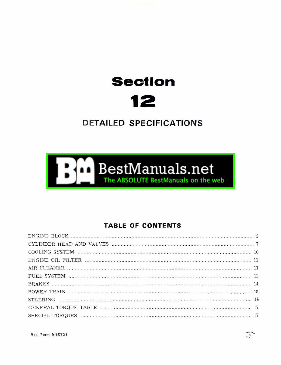
Section
12
DETAILED SPECIFICATION S
e
ser nendly
TABLE OF CONTENTS
ENGINE BLOCK "" .. .. . ........ ... ... .. ............ .. ...... .......... .. . ........ ....... .. ...... .. ........ ...... .. .... ............... 2
CYLINDER HEAD AND VALVES 7
COOLING SYSTEM . ... .. . ... 10
ENGINE OIL FILTER .. 11
AIR CLE ANER ............ .. ... .... ............. .......... ........ ...... , ....... ............... .. ........ , ..... ...... ,...... 11
FUE L SYSTEl\'[ .. .. ... .................. .. ..... ................ ...... ........ .. ' ........... ... ........ , .......... , ..... . ..... 12
BHAKES .. ... .. .... .. . ........ . .... . ... . ... ... .. .... .. '" 14
PO\VER TRAIN ... ... ...... ..... ..... .. ................. ....... .. .............. ....... " .' ....... .. ... . ... .... ....... ....... 15
STEERING .................... ..
.. ... .... ... .. .......... . 16
GE NERAL TORQUE TABLE ...... ........... ... ....... . ........ ...... ................ . .. ...... . . .... ........ ...... 17
SPECIAL TORQ UES .. .......... .... .. ........... .......................... ... .. .......... . .. 17
Rd". F orm 9 ·807 31
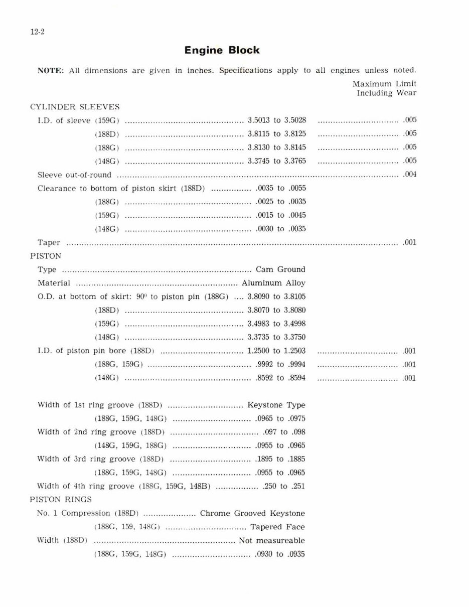
12-2
Engine Block
NOTE: All dimensions are given in inche s. Specifications apply to all engines unless noted.
C YLINDER S LEEVES
J.D. of sleeve (159C )
(1880 I
(l88C1
(l48G I
......... ........ . ............. .. ..... .. 3.5013 to 3.5028
...... .. ................. ......... .. .. ....... 3.8115 to 3.8125
.. .. ............ ... ............ ......... 3.81 30 to 3.8145
.... ................. .. .. .. ......... 3.3745 to 3.3765
Maximum Lim it
ln cluding Wear
.005
Sleeve out -o f· round ......... .... ... ... . .. ..... .. ......... .. ..... ....... .................... ................. ........ ...... .. .... .
.005
.005
.005
.004
Cleara nce to botlom of pi ston s kirt (188D) ................ . 0035 to .0055
(l88GI .. ... ... ...... . ................................... 0025 to .0035
(159C )
(!48GI
.0015 to .0045
.0030 to .0035
Tape r
PI STON
.. . .... ........ ....... ............. ....... ... .. ................ ......................... .. .. ..... . 001
Type ... ......................................... .. .......... .. .............. .. Cam Groun d
Mate ria l . .. ... ... ............ . .......... . ................... ........... Al um inum Alloy
G.D. at b ottom of s kirt : 90!! to piston pin (l88G ) . .. . 3.8090 to 3.8105
(1 88 01 . .. ......... .. .. ....................... 3.8070 to 3.8080
(!59G I ....... ... ........ ........ . ............ . ...... 3.4983 to 3. 499 8
(H SG I ......... ..... ......... ........... ............. 3.3735 to 3.3750
l. D. of piston pin b ore (18801 ................................. 1. 2500 to 1. 2503
(188C . 15SGI ... ..... .. ...... .. ....................... 9992 to .9994
(148G I . . ......... . ...................................... 859 2 to .8594
Wi dt h of 1st ring groove (lS!:!D) ..... ... _ .... . ................ Key stone Type
(18SG . 159G. " 8GI ................................ 0965 to .0975
Width of 2nd ring gr oove ll88D) ........... .. ....................... 09 7 to .098
( 148G , l 59G , J88G) . .. ......... .. .... .. .... ...... 0955 to .0965
Widt h of 3rd ring groov e (188 0) ................... . ............. 1895 to .1885
(l 88G. 159G, 148G) ..................... ........... 0955 to .0965
Width of 4th ring groove (l 88G, 159G. 148B ) ......... . .. . ..... 250 to .251
PI STON RINGS
No .1 Comp r ess ion (188D) ............ .. .. Ch rome Grooved Key sto ne
(l 88G. 1 59 . 1 -l 8G) ..... ................ ........... Tapered F ace
Width (188D ) ............ ... .. ....... .. ............. . ........ .. ..... Not meas ureable
(l88G. !S9G. "8G ) .... ..................... . 0930 to .0935
.OO!
.001
.U01
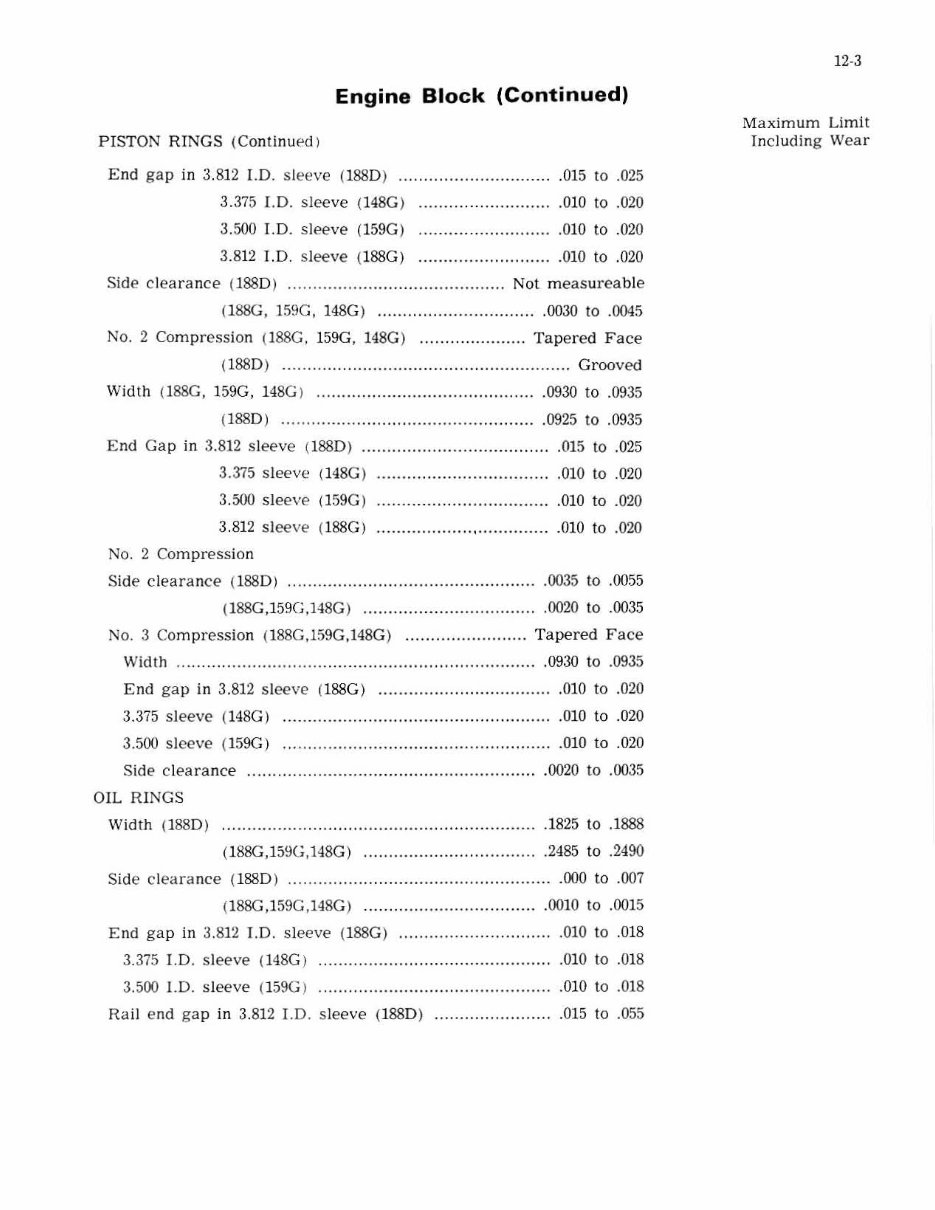
Engine Block (Continued)
P ISTON RINGS (Continued)
End gap in 3. 812 LD. slee ve (1 880) ... .. ....... ............ ... ... 015 to .025
3.375 I.D. sleeve ( H8G )
3.500 J.D. sl eeve (159G)
3.812 T. D. sleeve (ISSG)
.010 to .020
.010 to .020
.010 to .020
Side clearance (1880) ....................... . ............. ...... Not meas ureab Je
(188G. 159G. H SG ) ................................ 0030 to .0045
No.2 Compr ession (l88G, 159G , 148G) ............. __ ...... T apered Face
(188D) .... . .................................................... Grooved
Width (188G . 159G. 148G ) .. ....... .. .. ............................ ... 0930 to .0935
( l88D ) ..... .............................................. 0925 to .0935
End Gap in 3.812 sleeve (l88D) ........................ .............. 015 to .025
3.315 s l eeve (H8G ) ........ ...... . .................... 010 to .020
3.500 s l eeve (159G )
3 .812 slee ve (l88G)
No. 2 Compression
Side clearance (1880 )
.010 to .020
................... , ............... 010 to .020
.0035 to .0055
(I88G.159G.14SG) ................................... 0020 to .0035
No.3 Compression (188G.l59G.148G ) ........................ T ape r ed Face
\Vidth .......... ...... ............. .. . ...... . ................................. 0930 to .0935
End gap in 3.812 s l eeve (l88G ) ................................... 010 to .020
3.375 sleeve (14SG) ...................................................... 010 to .020
3.500 sleeve ( 159G) .... . ................................................. 010 to .020
Si de c learance ....................... . ...... . .......................... 0020 to .0035
OIL RINGS
\Vidt.h (l88D) .......... ...... ........ .... ........... .... . ........ . .......... 1825 to .1888
(188G,159G.148G) .. . ............ . ........... ........ 2485 to .2490
Side cleara nce (l 88D ) ... ..... ............................................. 000 to .007
(188G.159G .148G) ...... ............................. 0010 to .0015
End gap in 3.812 J.D. sleeve ( l88G ) ................. ... .. ......... 010 to .018
3.375 I.D. s leeve (H8G ) .010 to .018
3.500 1.0. sleeve (159G ) ..... .............. . ........................... 01 0 to .018
Rail e nd gap in 3.812 J.D. s leeve (188D) ........................ 015 to .055
12·3
Maximum Limit
Including Wear
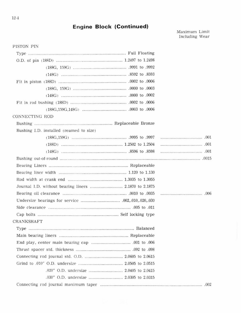
],·4
Engine Block (Continued)
PISTON P]N
Type ......................... ...... ................. .... ......... ... ........ Fu ll F loating
0.0. of pin (lAAD) ............... ..... . ............................ 1.2497 to 1.2498
1l88G , 109G ) .. . ..... .. . ,.,,"""""" ,999] to .9992
1148G ) ... "" . .... ". ,,"""""""" .8092 10 .8593
Fit in pi ston (188D )
(lS8G, 159G )
1l48G ) ""
F it in rod bu shing (1880 ) ................... ...... .. .
(188G.159G,148G ) .. . ............. . ......... .
CON:-.JECTTi\C HOD
,0002 to ,000 6
.0 000 to .0003
. 0000 to .(01)2
.0002 to .0006
.0003 to ,0006
Bushing ............ ......... ........... . . ......... .. Replaceable Bronze
Bushing I.D . inst a lled {reamed to size)
( 188G,159G) . ...... .. . ......... ... .. ..... .. ........... 9995 to .999 7
1 188D ) .. ..... .......... ... ................... 1. 2502 to 1.2504
1l48G ) ................. .. ....................... 8596 to .8598
Bushing out·ot-round ............... ...... ................. .......... ..... .. ....... ........ .. ......... .
Bearin g Liners ....... .......... .. .... ....... .......... ................... Repla ce able
B earing line r width ............. .. . ............................. 1.] 20 to 1.130
Rod width at cra nk cnd ...... . . " " , .......... " " .. . ... 1.3035 to 1.3055
Journal J.D. without bearin g liners .... .. .. ......... ........ 2.1870 to 2.1875
Bearing oil c leara nce ... .... ...... .................................... 0010 to .0035
Under size bcarings for serv ice ....... ..... ............... .. .002,. 010,.020, .030
Side clearance .................. . .. .............. .......................... 0 05 to .011
Cap bolts .... ... ... .. .. .................... ...... ........... ......... Self locking type
CRA:"J I{ SHA FT
Type ........... .......................... .......... .. ...... ............ ........ ..... Balanced
Main bearin g liners ..... .. ........ ........................... .... ....... Replacea ble
End play, center main bearing cap .... ..... .......... .
Thrust space r s td. thickness
.001 to .006
,092 to ,098
ConneCT in g rod journal std. 0. 0 . .................... ........ . 2.0605 to 2.0615
Grind to .010" 0.0 . undersize .. .... .... . .. ... .. ...... 2.0505 to 2.0515
.020" 0. 0. undersize
.030" 0. 0. un de rsize
2.0405 to 2.0415
2. 030 5 to 2.0315
Maximum Limit
ln c ludin g Wear
.00]
.001
... " ..... . " ,001
.. ............ ,0010
.006
Co nnecting ro cl journal m aximu m taper ........ .. ..... .......... ............... ..................... ... .... ... .... . ,002
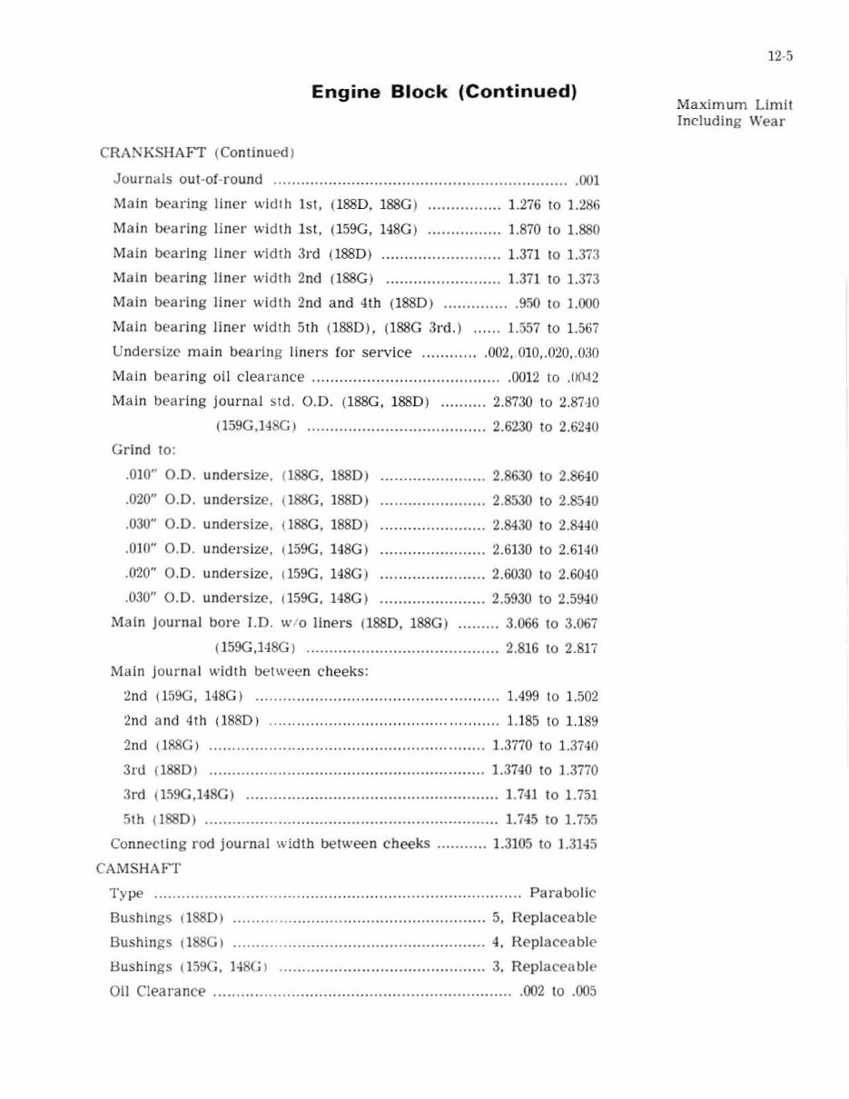
Engine Block (Continued)
CRAN KSHAFT (ContinuedJ
Journal s out-oC-round .............. .................... __ .. __ ........................ . (Xn
Main bearing liner wid th 1st, (I 88D , 188G) .............. __ 1.276 to 1.286
Main bearing liner width 1st, ( 159G, 148G) ............. __ . 1.870 to 1.880
Main bear in g lin er width 3rd (1880) .......................... 1.3il to 1. 373
Main bearing liner width 2nd (l 88G) ......................... 1.371 to 1.373
Main bearing liner width 2nd a nd 4th (1880) .... _____ ..... . 950 to 1.000
Main bearing liner width 5th (1880), (l 88C 3rd.l ...... 1.557 to 1.567
U nd ersize ma in bearing liners for service ............ . 002, .010,.020 .. 030
Main bearing o il clearance ......................................... . 0012 to .0042
Mai n bearing journal S Id. 0 .0 . (lSSG, 1880) .......... 2.8730 to 2.87 · jO
(159G ,148G ) ......... .............................. 2.6230 10 2.6240
Grind to:
.010" 0.0. undersi ze..
.020" 0.0. undersize,
.030" 0.0. und ersi ze ,
.010" 0.0. undersize,
.020" 0.0. und er size,
.030" 0.0. undersize,
(I88G, 1880 )
(I88G, 1880)
!l88G, 1880)
(l59G, 148G)
1159G, 148G)
(159G. 148G)
.. ..................... 2.8630 to 2.8&10
....................... 2.8530 10 2.8540
....................... 2.8430 10 2.8440
......... .............. 2.6130 10 2.6140
. ......... ............. 2.6030 10 2.6040
....................... 2.5930 to 2.59<1 0
Main journal bore 1.0 . w/o liners (1880, 188G) ......... 3.066 10 3.067
(159G,148G) ............................ . ............ 2.816 1 02.817
Main journal width between c heeks:
2nd (159G, 148G) ................................................. 1.499 10 1.502
2nd and 4Th (lB8D) .. .............. ................... ..... ... U85 10 U 89
2nd (188G) ....... . ................................... 1.3770 to 1.3740
3rd (1880) ....... .................................................... 1.3740 to ].3770
3rd (159G,148G) ....................................................... 1.741 to 1.751
5th (1880) ............... . .............. ..... ............................. 1.745 101.755
Connecting rod journal wid th bel wee n cheeks ........... 1. 3105 to 1. 3145
CAMSHM -r
Type ................................................................................ Parabolic
Bushings (I 88D) ............. .......................................... 5, Replaceable
Bushings (1SSG) ...... .... ........ ..................................... 4, Replaceable
Bushings (l59G . 148G ) .. ................ ........................... 3, Repla cea bl e
Oil Clearance ................................................................. . 002 to .005
12·5
Ma ximum Limit
Including Wear
12-6
En gine Block (Continued)
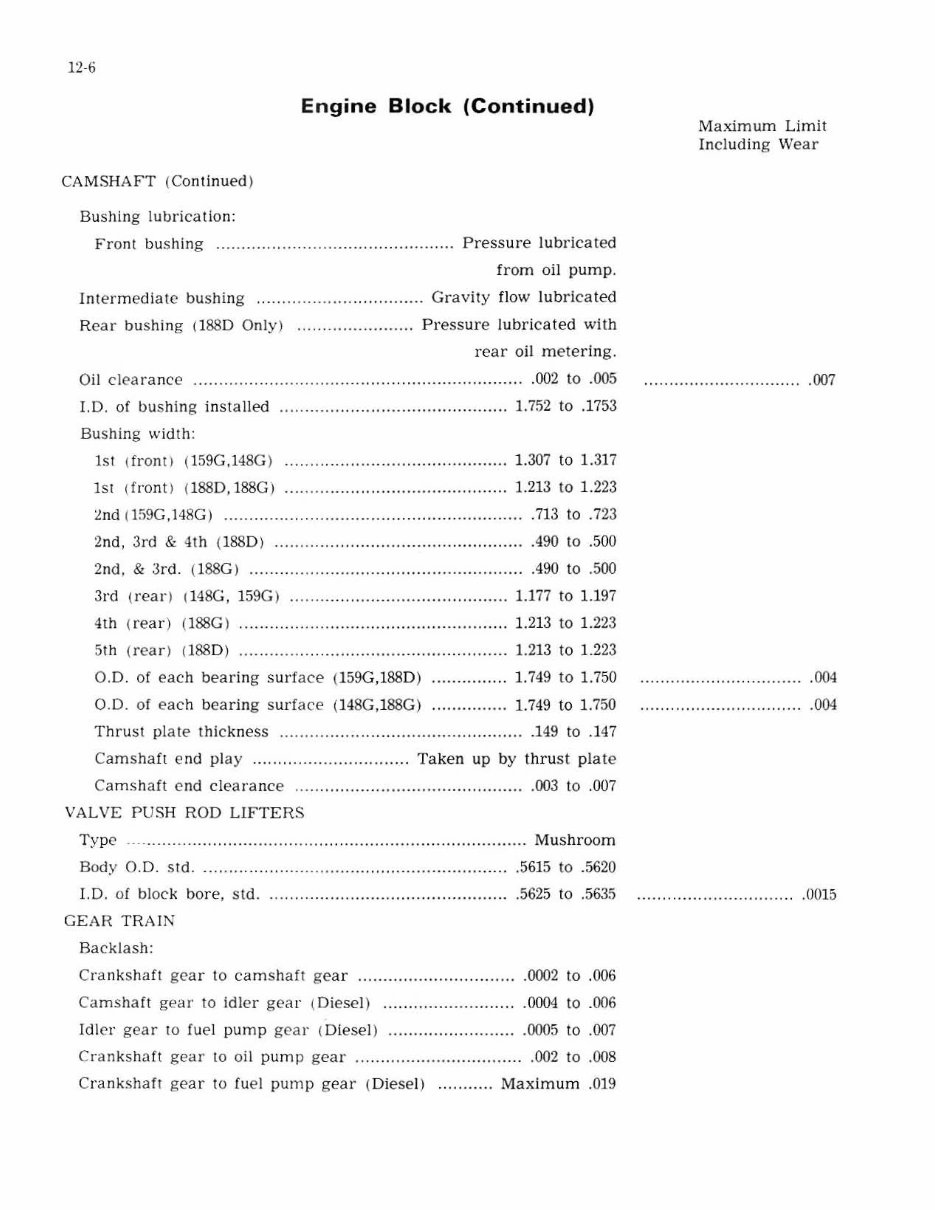
CAMSHAFT (Con tinued )
Bushing lubricat ion:
Front bushing ............... .. ..... .. ........ ............. . Pres s ure lubricated
fr om oil pump .
I ntermediate bushing ............ .. . .................. Gravity flow lubr ica ted
Rear bushing (1880 Only) ....................... Press ure l ubricated with
rear oil metering.
Oi l clearance ....... ........ .. .. ...... ..... ....... ....... ..................... 002 to .005
LD. of bushing installed ... . .. ....... ..... ............... ........... 1.752 to .1753
Bushing width:
lSI (fronO (159G,148G ) 1 .307 to 1. 317
lSI ( front) (1880, 188G) .......... ... ................. ............. 1.213 to 1.223
~nd (1 59G, 148G ) .. ......... ....... . ............... ........ ... ........ .... . 713 to .723
2nd, 3rd & 4th (1 88 0) .... .. .. ........... . ........... ............ .. . .490 to .500
2nd, & 3r d. ( l88G) ........... ......................................... .490 to .500
3rd (rear) 1 148G, 159G) ............. ...... ........................ 1.177 to 1.197
4th (re ar ) (188G ) ............. .. .................................. ... . 1.213 to 1.223
5th (re ar ) (188 0) ..... .. . .... ............................... . ......... 1.213 to 1. 223
0.0 . of each bearing surface (159G,188D)
0.0. of e ach bearing surfac e ( 148G ,188G)
1. 749 to 1.750
1.749 to 1.750
Thrust plale thic kne ss ... ... ................................ ........ ... 149 to .147
Cam s haft end play .. ............ . ................ Ta ke n up by thrust pla te
Camshaft cnd clearance ..... ............ ....... ................. .. ... 003 to .007
VALVE PUS H ROD LIFTER S
Type' .... ............. .. ...... ...... .......... ......... .... ..... .. ........ Mushroom
Body 0.0 . std .... . .. .... .. ........ ..... ................................. .
1.0. of block bore, std.
GEAR TRAIN
Backlash:
.5615 to .5620
.5625 to .56.15
Cranksh<'lfl g ear to camshaft ge ar ...... .. ............... .... ..... 0002 to .006
Camshaft gear to Idler gear ( Diesel) ................. . ......... 0004 to .006
Idler gear to fuel pump ge ar (Diesel) .......................... 0005 to .007
Crankshaft gear to oil pump gea r .. ......... ........... ........ .. .002 to .008
Crank s haft g ear to fuel pump gear (Di esel) ... ........ Maximum .0 ]9
Maximum Limit
Including Wear
...... ...................... . ... 007
.004
.004
.......................... ..... . 0015
You're Reading a Preview
What's Included?
Fast Download Speeds
Online & Offline Access
Access PDF Contents & Bookmarks
Full Search Facility
Print one or all pages of your manual
$32.99
Viewed 81 Times Today


Secure transaction
What's Included?
Fast Download Speeds
Online & Offline Access
Access PDF Contents & Bookmarks
Full Search Facility
Print one or all pages of your manual
$32.99
- The Case 450 Crawler Backhoe Loader Tractor Service & Repair Manual is an essential resource for professionals and enthusiasts working on this specific heavy machinery model.
- This official manual comprehensively covers maintenance, diagnostics, repair, and rebuilding, including hydraulic, electrical, engine, and transmission systems.
- It features high-quality diagrams, illustrations, and step-by-step instructions to ensure accurate repairs and troubleshooting.
- Designed for mechanics and operators, it provides manufacturer-approved methods and specifications for effective complex repairs and routine maintenance, preserving the machine's lifespan and reliability.
- Format: PDF
- Language: English
- Compatibility: Compatible with various electronic devices, including PC, Mac, Android, and Apple devices.
- Requirements: Adobe Reader (free)


