

Wacker BS50,BS60,BS70,BS500,BS600, Repair Manual
What's Included?
Fast Download Speeds
Online & Offline Access
Access PDF Contents & Bookmarks
Full Search Facility
Print one or all pages of your manual
0114549en 010 0510
0 1 1 4 5 4 9 E N
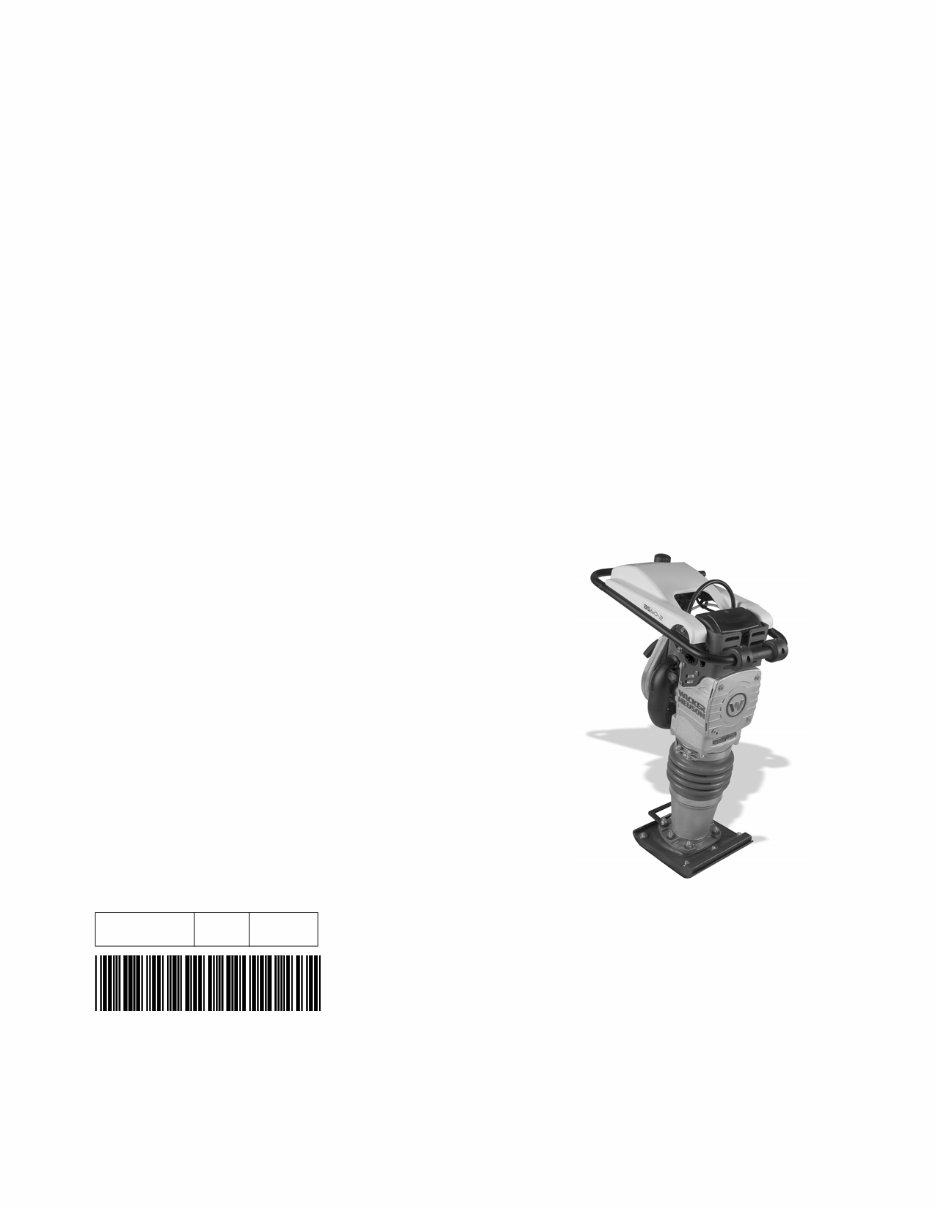
Repair Manual
Rammer
BS 50 / BS 60 / BS 70
BS 500 / BS 600 / BS 700
BS 65 / BS 650
DS 70 / DS 720

Copyright
notice
© Copyright 2010 by Wacker Neuson Corporation.
All rights, including copying and distribution rights, are reserved.
This publication may be photocopied by the original purchaser of the machine. Any
other type of reproduction is prohibited without express written permission from
Wacker Neuson Corporation.
Any type of reproduction or distribution not authorized by Wacker Neuson Corporation
represents an infringement of valid copyrights. Violators will be prosecuted.
Trademarks All trademarks referenced in this manual are the property of their respective owners.
Manufacturer Wacker Neuson Corporation
N92W15000 Anthony Avenue
Menomonee Falls, WI 53051 U.S.A.
Tel: (262) 255-0500 · Fax: (262) 255-0550 · Tel: (800) 770-0957
www.wackerneuson.com

Foreword
wc_tx001543gb.fm 3
Foreword
Machines covered in this manual.
Machine
documentation
Keep a copy of the Operator’s Manual with the machine at all times.
Use the separate Parts Book supplied with the machine to order replacement
parts.
If you are missing any of these documents, please contact Wacker Neuson
Corporation to order a replacement or visit www.wackerneuson.com.
When ordering parts or requesting service information, be prepared to provide
the machine model number, item number, revision number, and serial number.
BS 50-4 0009386, 0009415, 0620108, 0620071, 0620077, 0620078
BS 50-2 0009380, 0009382, 0009384, 0009410, 0009411, 0009413, 0620025,
0620048, 0620609, 0620610, 0620733, 0620609, 0620610, 0620733
BS 50-2i 0009332, 0009338, 0009383, 0009412, 0009414, 0009416, 0009473,
0620026, 0620611
BS 500 0007550, 0008048, 0008049, 0008204, 0009074, 0009075
BS 500-4 0009329
BS 500-oi 0009165, 0009343
BS 500S 0009211
BS 60-4 0009340, 0009422, 0620000, 0620051, 0620109, 0620110, 0620072,
0620073, 0620074, 0620483, 0620563, 0620812, 0620813, 0620816,
0620819, 0620820
BS 60-2 0009388, 0009391, 0009417, 0009418, 0009421, 0620612
BS 60-2i 0009339, 0009393, 0009419, 0009420, 0620613, 0620614
BS 600 0007551, 0008205, 0008207, 0009076, 0009077, 0009307
BS 600-4 0009331
BS 600-oi 0009166, 0009262
BS 600S 0009212
BS 70-2 0009397, 0009399, 0009424, 0009425, 0009427
BS 70-2i 0009341, 0009401, 0009426, 0009428
BS 700 0007552, 0008051, 0008052, 0008206, 0009078, 0009079, 0009308
BS 700-oi 0009167, 0009328
BS 65-V 0009396, 0009423
BS 650 0008209
DS 70 0009342, 0009402, 0009403, 0620049, 0620050, 0620052, 0620053,
0620054

Foreword
4 wc_tx001543gb.fm
Expectations
for
information in
this manual
This manual provides information and procedures to safely operate and main-
tain the above Wacker Neuson model(s). For your own safety and to reduce the
risk of injury, carefully read, understand, and observe all instructions described
in this manual.
Wacker Neuson Corporation expressly reserves the right to make technical
modifications, even without notice, which improve the performance or safety
standards of its machines.
The information contained in this manual is based on machines manufactured
up until the time of publication. Wacker Neuson Corporation reserves the right
to change any portion of this information without notice.
CALIFORNIA
Proposition
65 Warning
Engine exhaust, some of its constituents, and certain vehicle components, contain
or emit chemicals known to the State of California to cause cancer and birth
defects or other reproductive harm.
Laws
pertaining to
spark
arresters
NOTICE: State Health Safety Codes and Public Resources Codes specify that in
certain locations spark arresters be used on internal combustion engines that use
hydrocarbon fuels. A spark arrester is a device designed to prevent accidental dis-
charge of sparks or flames from the engine exhaust. Spark arresters are qualified
and rated by the United States Forest Service for this purpose. In order to comply
with local laws regarding spark arresters, consult the engine distributor or the local
Health and Safety Administrator.
Manufacturer’s
approval
This manual contains references to approved parts, attachments, and modifica-
tions. The following definitions apply:
Approved parts or attachments are those either manufactured or provided by
Wacker Neuson.
Approved modifications are those performed by an authorized Wacker Neu-
son service center according to written instructions published by Wacker Neu-
son.
Unapproved parts, attachments, and modifications are those that do not
meet the approved criteria.
Unapproved parts, attachments, or modifications may have the following conse-
quences:
Serious injury hazards to the operator and persons in the work area
Permanent damage to the machine which will not be covered under warranty
Contact your Wacker Neuson dealer immediately if you have questions about
approved or unapproved parts, attachments, or modifications.

wc_br0114549en_010TOC.fm 5
Table of Contents Rammer Repair
Foreword 3
1 Safety Information 9
1.1 Signal Words Found in this Manual ...................................................... 9
1.2 Machine Description and Intended Use ............................................. 10
1.3 Operating Safety ................................................................................ 11
1.4 Operator Safety while using Internal Combustion Engines ................ 13
1.5 Service Safety .................................................................................... 14
2 Tools 17
2.1 Recommended Special Tools ............................................................ 17
2.2 Recommended Repair Tools .............................................................. 18
3 Maintenance Schedules 19
3.1 Periodic Maintenance Schedule (BS 50/60/70-2, BS 65) ................... 19
3.2 Periodic Maintenance Schedule (BS 500/600/700/650) ..................... 20
3.3 Periodic Maintenance Schedule (BS 50/60/70-2i) .............................. 21
3.4 Periodic Maintenance Schedule (BS 500/600/700-oi) ........................ 22
3.5 Periodic Maintenance Schedule (DS 70) ........................................... 23
3.6 Periodic Maintenance Schedule (DS 720) ......................................... 24
4 Engine and Upper Machine Components 25
4.1 Removing the Silencing Cover ........................................................... 25
4.2 Replacing the Throttle Control (2010 and later 2-stroke models) ....... 26
4.3 Replacing the Throttle Control (2010 4-stroke models) ...................... 28
4.4 Throttle Control (pre-2010 models) .................................................... 31
4.5 Replacing the Stop Switch (2010 and later 2-stroke models) ............ 32
4.6 Replacing the Stop Switch (2010 and later 4-stroke models) ............ 35
4.7 Replacing the Guide Handle (2010 and later 2-stroke models) ......... 37
4.8 Replacing the Guide Handle (2010 and later 4-stroke models) ......... 40
4.9 Replacing the Guide Handle (pre-2010 models) ................................ 44
4.10 Shock Mounts ..................................................................................... 45

6 wc_br0114549en_010TOC.fm
Table of Contents Rammmer Repair
4.11 Tillotson Carburetor (BS 500/600/700/650 only) ................................. 46
4.12 Fuel Lines (BS 50/60/70-2, BS 65) ...................................................... 48
4.13 Fuel Tank (BS Models) ........................................................................ 49
4.14 Fuel Tank (DS Models) ....................................................................... 50
4.15 Fuel Tank Cap ..................................................................................... 52
4.16 Muffler (pre-2009 BS Models) ............................................................. 54
4.17 Engine Cooling Fins ............................................................................ 55
4.18 Muffler (DS Models) ............................................................................ 56
4.19 Replacing the Carburetor (WM 80 engines) ........................................ 58
4.20 Replacing the WM 80 Engine (2010 and later models) ....................... 62
4.21 Replacing the WM 80 Engine (pre-2010 models) ............................... 64
4.22 Replacing the Carburetor (WM 100 Engines) ..................................... 66
4.23 Replacing the WM 100 Engine ............................................................ 70
4.24 Removing the WM 90 Engine .............................................................. 74
4.25 Engine (DS Models) ............................................................................ 76
4.26 Clutch (2- and 4-stroke models) .......................................................... 78
4.27 Clutch (DS 720 only) ........................................................................... 80
4.28 Clutch (DS 70 only) ............................................................................. 82
5 Ramming System 84
5.1 Bellows ................................................................................................ 84
5.2 Replacing the Ramming Shoe ............................................................. 87
5.3 Spring System Cover Removal and Installation .................................. 90
5.4 Spring System ..................................................................................... 96
5.5 Inspecting the Spring System .............................................................. 98
5.6 Protective Pipe .................................................................................... 99
5.7 Ramming System Lubrication (BS 500/600/700/650, DS 720) ......... 100
5.8 Ramming System Lubrication (BS 50/60/70, BS 65, DS 70) ............ 102
6 Crankcase 104
6.1 Crank Gear and Connecting Rod ...................................................... 104
6.2 Crank Gear, Connecting Rod, and Adjuster Assembly (BS 650/65 only) 106
6.3 Clutch Drum ...................................................................................... 110

wc_br0114549en_010TOC.fm 7
Table of Contents Rammer Repair
7 Oil Injection (if equipped) 112
7.1 Testing the Float Switch (2010 and later models) ............................ 112
7.2 Replacing the Float Switch (2010 and later models) ........................ 114
7.3 Float Switch Testing and Replacement (pre-2010 models) ............. 116
7.4 Oil Line Check Valve ........................................................................ 118
7.5 Oil Pump / Cartridge Assembly ........................................................ 120
8 Low Oil Shutdown (if equipped) 123
8.1 Testing the Low Oil Unit ................................................................... 123
9 Troubleshooting 124
9.1 Engine Hard to Start ......................................................................... 124
9.2 Engine Does Not Start ...................................................................... 125
9.3 Engine Does Not Accelerate or Runs Poorly ................................... 125
9.4 Engine Overheats ............................................................................. 126
9.5 Rammer Does Not Tamp ................................................................. 126
9.6 Rammer Jumps Erratically ............................................................... 127
10 Technical Data 128
10.1 BS 50-2 ............................................................................................ 128
10.2 BS 50-4 ............................................................................................ 129
10.3 BS 500 .............................................................................................. 130
10.4 BS 500S ........................................................................................... 131
10.5 BS 50-2i ............................................................................................ 132
10.6 BS 500-oi .......................................................................................... 133
10.7 BS 60/70-2 ....................................................................................... 134
10.8 BS 60-4 ............................................................................................ 135
10.9 BS 600/700 ....................................................................................... 136
10.10 BS 600S ........................................................................................... 137
10.11 BS 60/70-2i ....................................................................................... 138
10.12 BS 600/700-oi ................................................................................... 139
10.13 BS 600/700 High Altitude ................................................................. 140
10.14 BS 65-V ............................................................................................ 141
10.15 BS 650 .............................................................................................. 142

8 wc_br0114549en_010TOC.fm
Table of Contents Rammmer Repair
10.16 DS 70 ................................................................................................ 144
10.17 DS 720 .............................................................................................. 146
Rammer Repair Safety Information
wc_si000514gb.fm 9
1 Safety Information
1.1 Signal Words Found in this Manual
This manual contains DANGER, WARNING, CAUTION, NOTICE, and
NOTE signal words which must be followed to reduce the possibility
of personal injury, damage to the equipment, or improper service.
NOTICE: Used without the safety alert symbol, NOTICE indicates a situation which, if not avoided,
could result in property damage.
Note: A Note contains additional information important to a procedure.
This is the safety alert symbol. It is used to alert you to potential personal hazards.
Obey all safety messages that follow this symbol.
DANGER
DANGER indicates a hazardous situation which, if not avoided, will result in death
or serious injury.
To avoid death or serious injury from this type of hazard, obey all safety mes-
sages that follow this signal word.
WARNING
WARNING indicates a hazardous situation which, if not avoided, could result in
death or serious injury.
To avoid possible death or serious injury from this type of hazard, obey all safety
messages that follow this signal word.
CAUTION
CAUTION indicates a hazardous situation which, if not avoided, could result in
minor or moderate injury.
To avoid possible minor or moderate injury from this type of hazard, obey all
safety messages that follow this signal word.

Safety Information Rammer Repair
10 wc_si000514gb.fm
1.2 Machine Description and Intended Use
This machine is a vibratory rammer. The Wacker Neuson Rammer
consists of a gasoline or diesel engine, a clutch, a fuel tank, a spring-
loaded ramming system, a ramming shoe, and a handle. The engine
transmits power through the ramming system and ramming shoe,
generating percussive impact force to compact soil. The operator
guides and controls the machine from behind using the handle.
This machine is intended to be used for compacting cohesive, mixed,
and granular soils in confined areas.
This machine has been designed and built strictly for the intended use
described above. Using the machine for any other purpose could
permanently damage the machine or seriously injure the operator or
other persons in the area. Machine damage caused by misuse is not
covered under warranty.
The following are some examples of misuse:
• Using the machine as a ladder, support, or work surface
• Using the machine to carry or transport passengers or equipment
• Using the machine as a hammer or for other demolition work
• Attaching the machine to any other machine
• Operating the machine outside of factory specifications
• Operating machine in a manner inconsistent with all warnings
found on the machine and in the Operator’s Manual
This machine has been designed and built in accordance with the
latest global safety standards. It has been carefully engineered to
eliminate hazards as far as practicable and to increase operator
safety through protective guards and labeling. However, some risks
may remain even after protective measures have been taken. They
are called residual risks. On this machine, they may include exposure
to:
• Heat, noise, exhaust, and carbon monoxide from the engine
• Fire hazards from improper refueling techniques
• Fuel and its fumes
• Personal injury from improper lifting techniques or operating
techniques
To protect yourself and others, make sure you thoroughly read and
understand the safety information presented in this manual before
operating the machine.
You're Reading a Preview
What's Included?
Fast Download Speeds
Online & Offline Access
Access PDF Contents & Bookmarks
Full Search Facility
Print one or all pages of your manual
$31.99
Viewed 69 Times Today


Secure transaction
What's Included?
Fast Download Speeds
Online & Offline Access
Access PDF Contents & Bookmarks
Full Search Facility
Print one or all pages of your manual
$31.99
- This is a complete factory service repair workshop manual for the BS and DS series rammers.
- The Service Manual contains easy-to-read text sections with top quality diagrams and instructions.
- It provides step-by-step instructions and highly detailed exploded pictures and diagrams to guide you through any repair efficiently.
- The Workshop Manual covers every single detail on your machine, making it especially helpful for carb adjustments.
- It covers the following models:
- BS 50-4 0009386, 0009415, 0620108, 0620071, 0620077, 0620078
- BS 50-2 0009380, 0009382, 0009384, 0009410, 0009411, 0009413, 0620025, 0620048, 0620609, 0620610, 0620733, 0620609, 0620610, 0620733
- BS 50-2i 0009332, 0009338, 0009383, 0009412, 0009414, 0009416, 0009473, 0620026, 0620611
- BS 500 0007550, 0008048, 0008049, 0008204, 0009074, 0009075
- BS 500-4 0009329
- BS 500-oi 0009165, 0009343
- BS 500S 0009211
- BS 60-4 0009340, 0009422, 0620000, 0620051, 0620109, 0620110, 0620072, 0620073, 0620074, 0620483, 0620563, 0620812, 0620813, 0620816, 0620819, 0620820
- BS 60-2 0009388, 0009391, 0009417, 0009418, 0009421, 0620612
- BS 60-2i 0009339, 0009393, 0009419, 0009420, 0620613, 0620614
- BS 600 0007551, 0008205, 0008207, 0009076, 0009077, 0009307
- BS 600-4 0009331
- BS 600-oi 0009166, 0009262
- BS 600S 0009212
- BS 70-2 0009397, 0009399, 0009424, 0009425, 0009427
- BS 70-2i 0009341, 0009401, 0009426, 0009428
- BS 700 0007552, 0008051, 0008052, 0008206, 0009078, 0009079, 0009308
- BS 700-oi 0009167, 0009328
- BS 65-V 0009396, 0009423
- BS 650 0008209
- DS 70 0009342, 0009402


