

Collection of 5 files - Complete Factory Case 530CK Loader Backhoe Repair Service Manual & Illustrated Parts Catalog & Operators
What's Included?
Fast Download Speeds
Online & Offline Access
Access PDF Contents & Bookmarks
Full Search Facility
Print one or all pages of your manual

I
!i\THIS SAFETY ALERT SYMBOL INOICATES IMPORTANT SAFETY
'
MESSAGES IN THIS MANUAL. WHEN YOU SEE THIS SYMBOL,
CAREFULL Y READ THE MESSAGE THAT FOLLOWS AND BE
• ALERT TO THE POSSIBILITY OF PERSONAL INJURY OR
DEA TH. M1718
Safety Decals on this machine use the words Danger, Warning or
Caution, which are defined as follows:
• DANGER: Indicates an immediate hazardous situation which. if
not avoided. will result in death or serious injury. The color
associated with Danger is RED.
• WARNING: Indicates a potentially hazardous situation which. if
not avoided will result in serious injury. The color associated with
Warning is ORANGE.
• CAUTION: Indicates a potentially hazardous situation which. if
not avoided. may result in minor or moderate injury. It may also
be used to alert against unsafe practices. The color associated
with Caution is YELLOW.
IMPROPER OPERATION OF THIS MACHINE CAN CAUSE INJURY OR
DEATH. BEFORE USING THIS MACHINE, MAKE CERTAIN THAT EVERY
OPERATOR:
• Is instructed in safe and proper use of the machine.
• Reads and understands the Manual(s) pertaining to the machine.
• Reads and understands ALL Safety Decals on the ma~hine.
• Clears the area of other persons.
• Learns and practices safe use of machine controls in a safe, clear area
before operating this machine on a job site
It is your responsibility to observe pertinent laws and regulations and follow
Case Corporation instructions on machine operation and maintenance.
<CI 1996 Case Corporation
CASE and IH are registered trade marks of Case Corporation
••
CABE®·
"32"
r
•
•
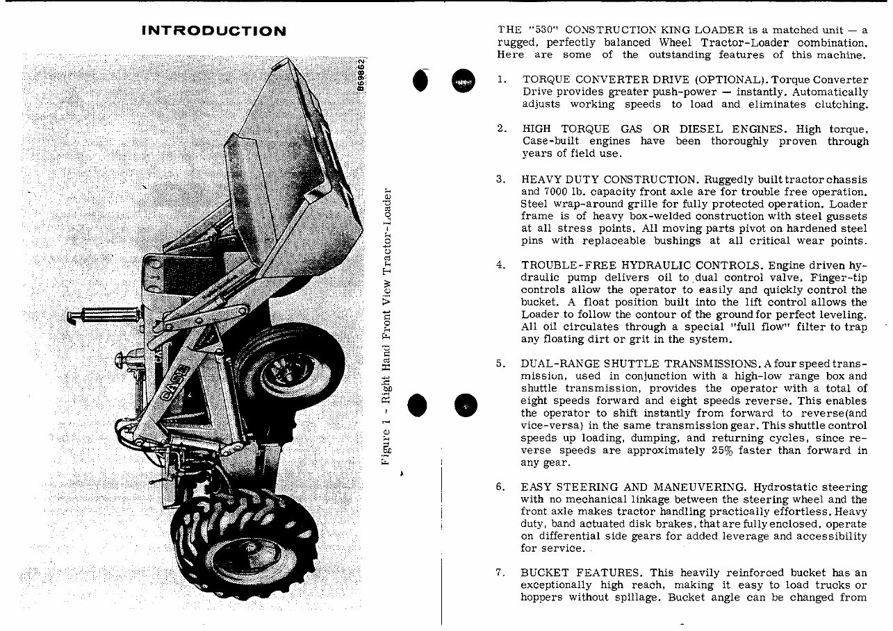
INTRODUCTION
'"
Q)
"C
oj
0
...:I
I
'"
0
-
"
oj
....
f-<
"
Q)
:;
-
"
0
'"
""'
"
"
oj
::c:
-
..c:
blJ
.~
~
~
Q)
'"
.§O
""'
•
•
• •
THE "530" CONSTRUCTION KING LOADER is a matched unit - a
rugged. perfectly balanced Wheel Tractor-Loader combination.
Here are some of the outstanding features of this machine .
1. TORQUE CONVERTER DRIVE (OPTIONAL). Torque Converter
Drive provides greater push-power - instantly. Automatically
adjusts working speeds to load and eliminates clutching.
2. HIGH TORQUE GAS OR DIESEL ENGINES. High torque.
Case-built engines have been thoroughly proven through
years of field use.
3. HEAVY DUTY CONSTRUCTION. Ruggedly built tractor chassis
and 7000 lb. capacity front axle are for trouble free operation.
Steel wrap-around grille for fully protected operation. Loader
frame is of heavy box-welded construction with steel gussets
at all stress pOints. All moving parts pivot on hardened steel
pins with replaceable bushings at all critical wear points.
4. TROUBLE-FREE HYDRAULIC CONTROLS. Engine driven hy-
draulic pump delivers oil to dual control valve. Finger-tip
controls allow the operator to easily and quickly control the
bucket. A float position built into the lift control allows the
Loader to follow the contour of the ground for perfect leveling.
All oil circulates through a special "full flow" filter to trap
any floating dirt or grit in the system.
5. DUAL-RANGE SHUTTLE TRANSMISSIONS. Afoul' speed trans-
missiun. used in conjunction with a high-low range box and
shuttle transmission. provides the operator with a total of
eight speeds forward and eight speeds reverse. This enables
the operator to shift instantly from forward to reverse(and
vice-versa) in the same transmission gear. This shuttle control
speeds up loading. dumping. and returning cycles. since re-
verse speeds are approximately 25% faster than forward in
any gear.
6. EASY STEERING AND MANEUVERING. Hydrostatic steering
with no mechanical linkage between the steering wheel and the
front axle makes tractor handling practically effortless. Heavy
duty. band actuated disk brakes. that are fully enclosed. operate
on differential side gears for added leverage and accessibility
for service ..
7. BUCKET FEATURES. This heavily reinforced bucket has an
exceptionally high reach. making it easy to load trucks or
hoppers without spillage. Bucket angle can be changed from
a 1100 forward roll to a 40' rollback at ground level. Dump
angle is 45'. Roll forward for backfilling or grading and roll-
back for easy "breakout" when filling the bucket.
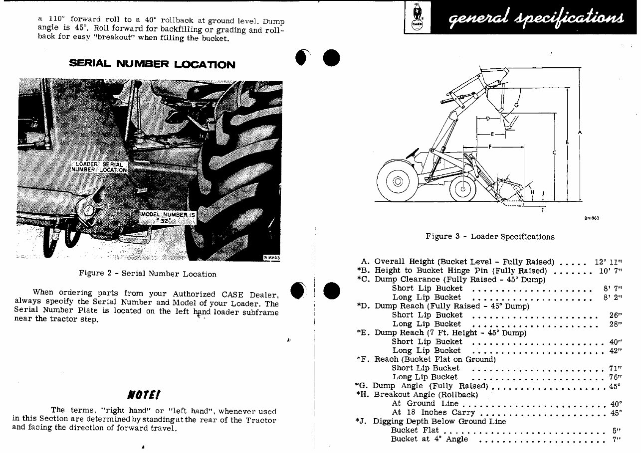
SERIAL NUMBER LOCATlON
Figure 2 - Serial Number Location
When ordering parts from your Authorized CASE Dealer.
always specify the Serial Number and Model of your Loader. The
Serial Number Plate is located on the left hf',nd loader subframe
near the tractor step. . .
NOrtl
The terms, "right hand" or "left hand". whenever useci
in this Section are determined by stanciing at the rear of the Tractor
and facing the direction of forward travel.
•
.,.
•
,.
A
B
c
SNI863
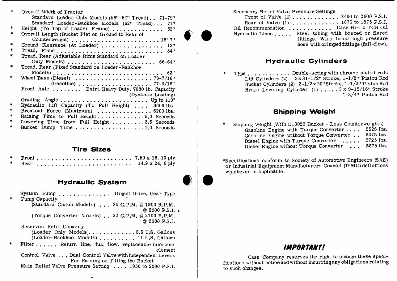
Figure 3 - Loader Specifications
A. Overall Height (Bucket Level - Fully Raised) •• • •• 12' 11"
*B. Height to Bucket Hinge Pin (Fully Raised) ••.•.•• 10' 7"
*C. Dump Clearance (Fully Raised - 45' Dump)
Short Lip Bucket ..................... 8' 7"
Long Lip Bucket •••••.•••.••..••.•••• 8' 2"
*D. Dump Reach (Fully Raised - 45' Dump)
Short Lip Bucket ••••••.••••.•••••••••• 26"
Long Lip Bucket •••••••••••••••••••••• 28"
*E. Dump Reach (7 Ft. Height - 45' Dump)
Short Lip Bucket ......................... 40"
Long Lip Bucket .••••...•..••••.•••••.• 42"
*F. Reach (Bucket Flat on Ground)
Short Lip Bucket ......... , ............. 71"
Long Lip Bucket • • • • • . . • • . • • • • • . . • . • • . • 76"
*G. Dump Angle (Fully Raised) ••.••••.••..•••••••. 45'
*H. Breakout Angle (Rollback)
At Ground Line •.•••••••••..•.••••...•.• 40'
At 18 Inches Carry ••.••.•..••••.•••••••• 45'
*J. Digging Depth Below Ground Line
Bucket Flat . . .. .. . . . . . . . . . . . . . . . . . . . . . . .. 5
'1
Bucket at 4
0
Angle ...................... 7"
,.
*
,.
..
..
..
*
*
..
*
*
*
of<
*
*
..
*
Overall Width of Tractor
Standard Loader Only Models (56"-64" Tread) •• 71-79"
Standard Loader-Backhoe Models (62" Tread)... 77"
Height (To Top of Loader Frame) • • • . • • • • • • • • •• 62"
Overall Length (Bucket Flat on Ground to Rear of
Counterweight) ........ •..• ..... •• .... • 15' 7"
Ground Clearance (At Loader) ••.•• . . • • • • • • • • •• 12"
Tread, Front ............................. 54"
Tread, Rear (Adjustable Rims Standard on Loader
Only Models) ••• • • . • • • . • • . . . • • • • • • • •• 56-64"
Tread, Rear (Fixed Standard on Loader-Backhoe
Models) . • . . . • . • • • • . • • • • • • • • • • • • • • . . •• 62"
Wheel Base (Diesel) ••.•••.•••••••••••••• 78-7/16"
(Gasoline) •••••••••..•••••••.• 77-3/16"
Front Axle .••.•••• Extra Heavy Duty, 7000 lb. Capacity
(Dynamic Loading)
Grading Angle ........................ Up to 110'
Hydraulic Lift Capacity (To Full Height) ••.• 3000 lbs.
Breakout Force (Maximum) •.•••.•.••.••.• 6200 lbs.
RaiSing Time to Full Height • ..... ••.••.. 5.0 Seconds
Lowering Time from Full Height .•• ...... 3.5 Seconds
Bucket Dump Time ...• ............... 1.0 Seconds
Tire Sizes
Front . . . . . . . . . . . . . . . . . . . . . . . . ..
Rear .••..•.•..•.• ••••••• ..... •
Hydraulic System
7.50 x 16, 10 ply
14.9 x 24, 6 ply
System Pump . . • • • • • • • • • . •. Dir.e?t Drive, Gear Type
Pump Capacity
(Standard Clutch Models) ••. 20 G.P.M. @ 1900 R.P.M.
@ 2000 P.S.I. .'
(Torque Converter Models) •• 22 G.P.M. @ 2100 R.P.M.
@ 2000 P.S.I.
Reservoir Refill Capacity
(Loader Only Models) ••.•••••.•.•• 5.5 U.S. Gallons
(Loader-Backhoe Models) •..••••••• 11 U.S. Gallons
Filter. • • • •. Return line, full flow, replaceable micronic
element
Control Valve ••• Dual Control Valve with Independent Levers
For Raising or Tilting the Bucket
Main Relief Valve P,:essure Setting .••• 1950 to 2000 P.S.I.
f'.
• •
•
•
Secondary Relief Valve Pressure Settings
Front of Valve (2) ••••.•••••••• 2400 to 2600 P.S.I.
Rear of Valve (1) ..... ••••..•. 1675 to 1875 P.S.I.
Oil Recommendation •••••.••••.• Case Hi-Lo TCH Oil
Hydraulic Lines. . . .• Steel tubing with brazed or flared
fittings. Wire braid high pressure
hose with crimped fittings (full-flow) •
Hydraulic Cylinders
Type ..••.•..••.• Double-acting with chrome plated rods
Lift Cylinders (2) 3x 31-1/2" Stroke, 1-1/2" Piston Rod
Bucket Cylinders (2) 2-1/2 x 20" Stroke, 1-1/2" Piston Rod
Hydra-Leveling Cylinder (1) ••.•• 3 x 9-15/16" Stroke
1-3/4" Piston Rod
Shipping Weight
Shipping Weight (With 013022 Bucket - Less Counterweights)
Gasoline Engine with Torque Converter. • .• 5525 lbs.
Gasoline Engine without Torque Converter •• 5375lbs.
Diesel Engine with Torque Converter ••••• 5725 lbs.
Diesel Engine without Torque Converter 5575 lbs.
'Specifications conform to Society of Automotive Engineers (SAE)
or Industrial Equipment Manufacturers Council (IEMC) definitions
whichever is applicable .
IMPORTANT!
Case Company reserves the right to change these speci-
fications without notice and without inc.urring any obligations relating
to such changes.
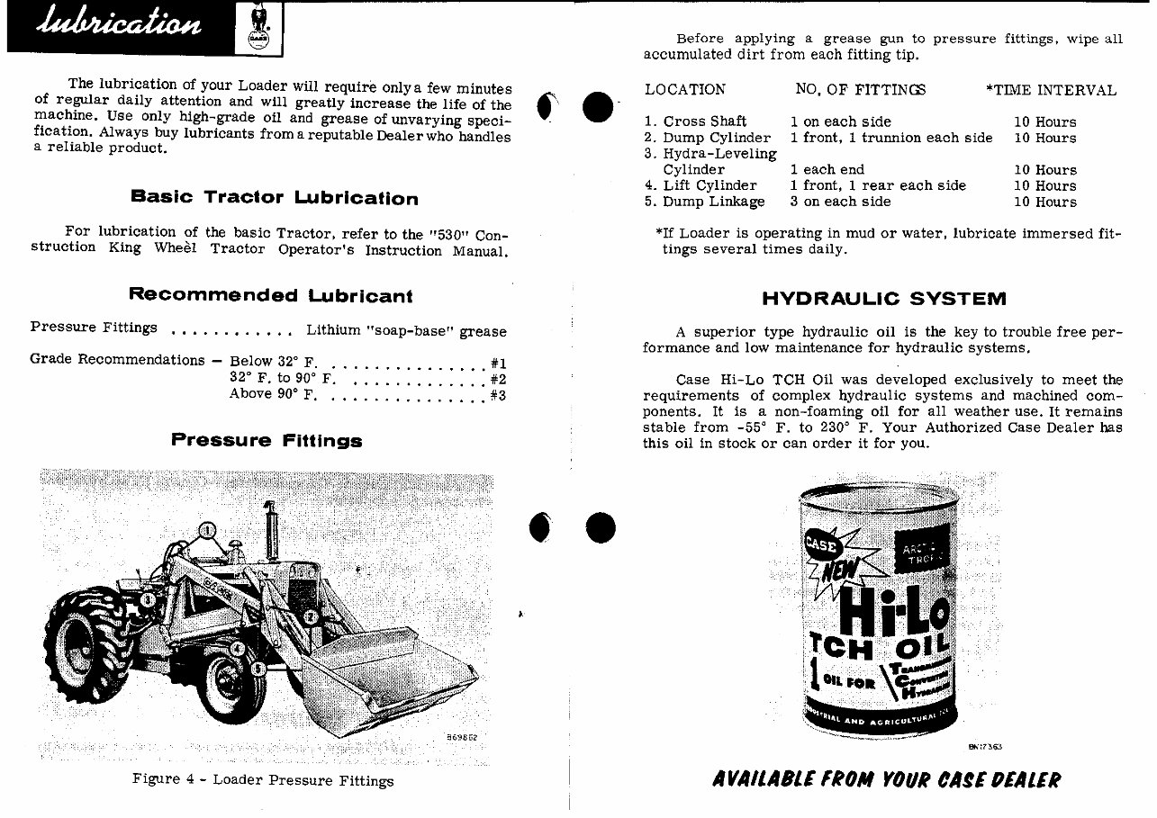
The lubrication of your Loader will require only a few minutes
of regular daily attention and will greatly increase the life of the
,:,ac~ine. Use only high-grade oil and grease of unvarying speci-
fIcatIOn. Always buy lubricants from a reputable Dealer who handles
a reliable product.
Basic Tractor Lubrication
For lubrication of the baSic Tractor. refer to the "530" Con-
struction King WheeH Tractor Operator's Instruction Manual.
Recommended Lubricant
Pressure Fittings .•••..•..•.. Lithium "soap-base" grease
Grade Recommendations - Below 32
0
F. . ............ •. #1
32
0
F. to 90
0
F. . ............ #2
Above 90
0
F. . .............. #3
Pressure Fittings
Figure 4 - Loader Pressure Fittings
f ."
• •
Before applying a grease gun to pressure fittings, wipe all
accumulated dirt from each fitting tip.
LOCATION
1. Cross Shaft
2. Dump Cylinder
3. Hydra-Leveling
Cylinder
4. Lift Cylinder
5. Dump Linkage
NO, OF FITTINGS *TIME INTERVAL
1 on each side
1 front, 1 trunnion each side
10 Hours
10 Hours
1 each end
1 front. 1 rear each side
3 on each side
10 Hours
10 Hours
10 Hours
*If Loader is operating in mud or water, lubricate immersed fit-
tings several times daily.
HYDRAULIC SYSTEM
A superior type hydraulic oil is the key to trouble free per-
formance and low maintenance for hydraulic systems.
Case Hi-Lo TCH Oil was developed exclusively to meet the
requirements of complex hydraulic systems and machined com-
ponents. It is a non-foaming oil for all weather use. It remains
stable from _55
0
F. to 230
0
F. Your Authorized Case Dealer has
this oil in stock or can order it for you .
AVAILABLE IROM YOUR CAfE fJEALER
Reservoir Refill Capacity (Loader only) •.•• 5-1/2 U.S. Gallons
(Loader-Backhoe) .,. 11 U.S. Gallons
*Oil Recommendations ••••• .... ••... Case Hi-Lo TCH Oil
*As an alternate oil, a heavy-duty motor oil meeting American f: •
Petroleum Institute service designation. MS-DG. may be used. -
Use only a good grade oil with non-foaming characteristics.
Viscosity Recommendations (Above 32' F.)
(Below 32' F.)
SAE 10-W
*SAE 5-W
*If SAE 5-W oil is not obtainable, Automatic Transmission
Oil, type nAn may b~ used.
IMPORTANTI
DIRT IS THE ENEMY OF ANY HYDRAULIC SYSTEM. THE
BEST WAY 'TO FIGHT THIS ENEMY IS TO PREVENT ITS
ENTRY INTO THE SYSTEM. WHEN ADDING OIL BE SURE
OIL, FUNNELS, AND CONTAINERS ARE CLEAN.
NO TEl
CHEAP GRADES OF OIL ARE NOT SUITABLE FOR USE IN
THE HYDRAULIC SYSTEM.
Checking Hydraulic Oil Level
The loader subframes serve as reservoirs for the hydraulic
oil. If the Tractor is equipped with a Loader only, just right
hand reservoir contains hydraulic oil. If the Tractor is equipped
with a Loader and Backhoe (or has provision for installing a
Backhoe). both reservc:>irs are used. Drain plugs are locateq,
at the elbow in the bottom of the reservoirs.
In order to obtain an accurate measurement of the reservoir
oil level:
1. Have the Tractor standing on a level surface.
2. Run the Tractor until the hydraulic system warms up (reservoir
is warm to the touch).
3. Lower the bucket to ground level, and roll it back.
•
I.'
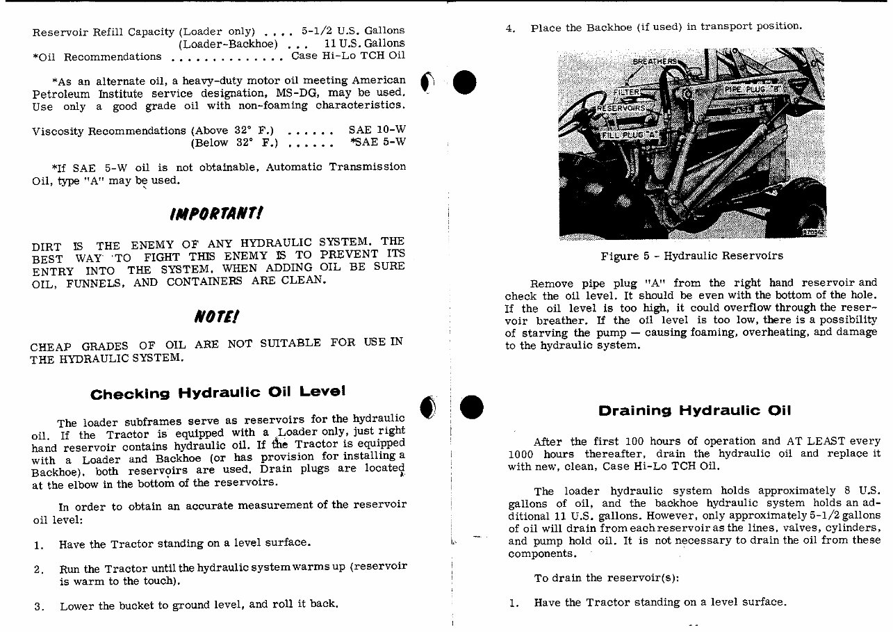
4. Place the Backhoe (if used) in transport position.
Figure 5 - Hydraulic Reservoirs
Remove pipe plug nAn from the right hand reservoir and
check the oil level. It should be even with the bottom of the hole.
If the oil level is too high. it could overflow through the reser-
voir breather. If the oil level is too low, there is a possibility
of starving the pump - causing foaming, overheating, and damage
to the hydraulic system.
Draining Hydraulic Oil
After the first 100 hours of operation and AT LEAST every
1000 hours thereafter, drain the hydraulic oil and replace it
with new. clean, Case Hi-Lo TCH Oil.
The loader hydraulic system holds approximately 8 U.S.
gallons of oil. and the backhoe hydraulic system holds an ad-
ditional 11 U.S. gallons. However, only approximately 5-1/2 gallons
of oil will drain from each reservoir as the lines. valves, cylinders,
and pump hold oil. It is not necessary to drain the oil from these
components. '
To drain the reservoir(s):
1. Have the Tractor standing on a level surface.
2. Run the Tractor until the hydraulic system warms up (reser-
voir is warm to the touch),
3. Lower the bucket to ground level and roll it back.
4. Place the Backhoe (if used) in transport position.
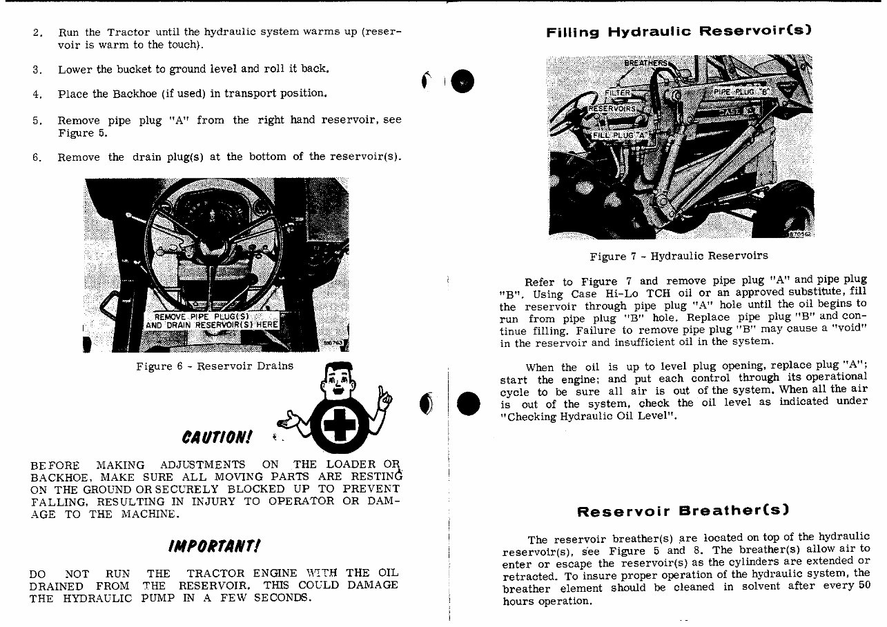
5. Remove pipe plug "A" from the right hand reservoir, see
Figure 5.
6. Remove the drain plug(s) at the bottom of the reservoir(s).
Figure 6 - Reservoir Drains
CAUTION!
BEFORE MAKING ADJUSTMENTS ON THE LOADER OR
BACKHOE, MAKE SURE ALL MOVING PARTS ARE RESTINC'
ON THE GROUND OR SECURELY BLOCKED UP TO PREVENT
FALLING, RESULTING IN INJURY TO OPERATOR OR DAM-
AGE TO THE MACHINE.
DO NOT RUN
DRAINED FROM
THE HYDRAULIC
IMPORTANT!
THE TRACTOR ENGINE WITH THE OIL
THE RESERVOIR. THIS COULD DAMAGE
PUMP IN A FEW SECONDS.
Filling Hydraulic Reservoir(s)
Figure 7 - Hydraulic Reservoirs
Refer to Figure 7 and remove pipe plug "A" and pipe plug
"B". Using Case Hi-Lo TCH oil or an approved substitute, fill
the reservoir through pipe plug "A" hole until the oil begins to
run from pipe plug "B" hole. Replace pipe plug "B" and con-
tinue filling. Failure to remove pipe plug "B" may cause a "void"
in the reservoir and insufficient oil in the system.
When the oil is up to level plug opening, replace plug" A";
start the engine; and put each control through its operational
cycle to be sure all air is out of the system. When all the air
is out of the system, check the oil level as indicated under
"Checking Hydraulic Oil Level".
Reservoir Breather(s)
The reservoir breather(s) ,are located on top of the hydraulic
reservoir(s), see Figure 5 and 8. The breather(s) allow air to
enter or escape the reservoir(s) as the cylinders are extended or
retracted. To insure proper operation of the hydraulic system. the
breather element should be cleaned in solvent after every 50
hours operation.
,
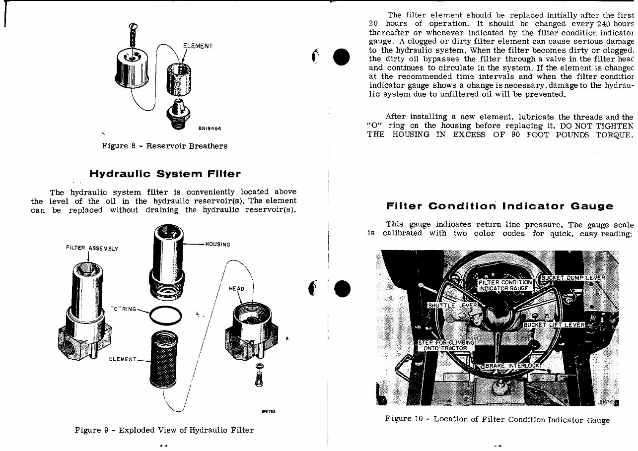
Figure 8 - Reservoir Breathers
Hydraulic System Filter
The hydraulic system filter is conveniently located above
the level of the oil in the hydraulic reservoir(s). The element
can be replaced without draining the hydraulic reservoir(s).
FILTER ASSEMBLY
"O"RING--Q
ELEMENT
---HeWSING
.~
/ \
/ )
, /
/
/
/
Figure 9 - Exploded View of Hydraulic Filter
.'
91'111763
~ .•
•
The filter element should be replaced initially after the first
20 hours of operation. It should be changed every 240 hourE
thereafter or whenever indicated by the filter condition indicator
gauge. A clogged or dirty filter element can cause serious damag€
to the hydraulic system. When the filter becomes dirty or Clogged,
the dirty oil bypasses the filter through a valve in the filter heat
and continues to circulate in the system, If the elem3nt is changec
at the recommended time intervals and when the filter conditior
indicator gauge shows a change is necessary, damage to the hydrau-
lic system due to unfiltered oil will be prevented.
After installing a new element, lubricate the threads and the
"0" ring on the housing before replacing it. DO NOT TIGHTEN
THE HOUSING IN EXCESS OF 90 FOOT POUNDS TORQUE.
Filter Condition Indicator Gauge
This gauge indicates return line pressure. The gauge scale
is calibrated with two color codes for quick, easy reading:
Figure 10 - Location of Filter Condition Indicator Gauge
EARLY LATE
8N24763
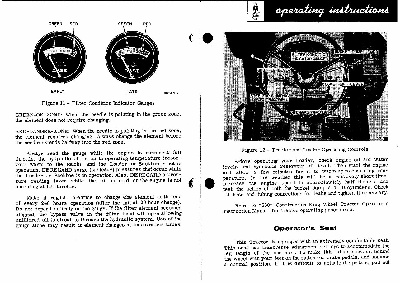
Figure 11 - Filter Condition Indicator Gauges
GREEN-OK-ZONE: When the needle is pointing in the green zone,
the element does not require changing.
RED-DANGER-ZONE: When the needle is pointing in the red zone,
the element requires changing. Always change the element before
the needle extends halfway into the red zone.
Always read the gauge while the engine is running at full
throttle, the hydraulic oil is up to operating temperature (reser-
voir warm to the touch), and the Loader or Backhoe is not in
operation. DlSRE GARD surge (unsteady) pressures that occur while
the Loader or Backhoe is in operation. Also, DlSREGARD a pres-
sure reading taken while the oil is cold or the engine is not ~
operating at full throttle. ~
Make it regular practice to change Uhe element at the end
of every 240 hours operation (after the initial 20 hour change).
Do not depend entirely on the gauge. If the filter element becomes
clogged, the bypass valve in the filter head will open allowing
unfiltered oil to circulate through the hydraulic system. Use of the
gauge alone may result in element changes at inconvenient times.
•
Figure 12 - Tractor and Loader Operating Controls
Before operating your Loader, check engine oil and water
levels and hydraulic reservoir oil level. Then start the engine
and allow a few minutes for it to warm up to operating tem-
perature. In hot weather this will be a relatively short time .
Increase the engine speed to approximately half throttle and
test the action of both the bucket dump and lift cylinders. Check
all hose and tubing connections for leaks and tighten if necessary.
Refer to "530" Construction King Wheel Tractor Operator's
Instruction Manual for tractor operating procedures.
Operator's Seat
This Tractor is equipped with an extremely comfortable seat.
This seat has transverse adjustment settings to accommodate the
leg length of the operator. To make this adjustment, sit behind
the wheel with your feet on the clutch and brake pedals, and assume
a normal position. If it is difficult to actuate the pedals, pull out
You're Reading a Preview
What's Included?
Fast Download Speeds
Online & Offline Access
Access PDF Contents & Bookmarks
Full Search Facility
Print one or all pages of your manual
$54.99
Viewed 77 Times Today


Secure transaction
What's Included?
Fast Download Speeds
Online & Offline Access
Access PDF Contents & Bookmarks
Full Search Facility
Print one or all pages of your manual
$54.99
- This collection includes the following products:
- Case 530 530CK Loader Backhoe Service Repair Manual - IMPROVED
- Case 530CK 530 Construction King Backhoe Loader Illustrated Parts Manual Catalog
- Case 530CK 530 Construction King Tractor Engine Illustrated Parts Manual Catalog
- Case 530CK Loader Backhoe Operators Owner Instruction Manual - IMPROVED
- Case 530CK Tractor Operators Owner Instruction Manual - IMPROVED
- All 5 manuals are available for less than other sellers charge for 1 manual.
- These manuals are useful for both professional mechanics and DIY enthusiasts.
- Additional Information: Documents may require the newest version of Acrobat Reader to display correctly. Should you have any problems reading your document, please initially try upgrading to the latest version of Adobe Acrobat Reader.
- If you only want one of these, let me know, and I will beat anyone's price.


