Allis Chalmers 715 Backhoe Loader Parts Catalog Manual
What's Included?
Lifetime Access
Fast Download Speeds
Online & Offline Access
Access PDF Contents & Bookmarks
Full Search Facility
Print one or all pages of your manual
PARTS CATALOG ALLIS-CHALMERS 715 BACKHOE- LOADER FORM 9004560 REPLACES 1012411 REVISED DEC. 1975 LITHO U.S.A.
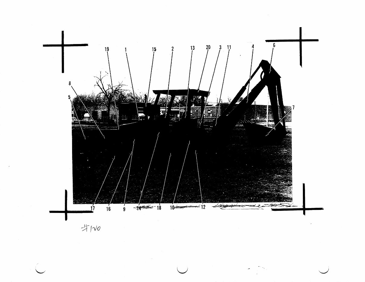
7 ( 71 5 Page 1 I GENERAL DESCRIPTION 1. AIR CLEANER (INTAKE) 11c STABILIZER CYLINDER 2. CONTROL PANEL 12. STABILIZER 3. CONTROLS (BACKHOE) 13. SEAT 4. BACKHOE BOOM 14. PEDAL CONTROLS 5. LOADER BUCKET 15. MUFFLER 6. BACKHOE DIPPERSTICK 16. BATTERY LOCATION 7. BACKHOE BUCKET 17. FRONT AXLE AND TIRE 8. DUMP CYLINDER (LOADER) 18. REAR AXLE AND TIRE 9. LOADER CYLINDER 19. GRILLE 10. SWING CYLINDER (BEHIND TIRE & FRAME 20. CANOPY L. H. & R. H. SIDE OF LOADER AND BACKHOE THE L. H. -& R. H. SIDE OF THIS EQUIPMENT IS DESIGNATED BY THE OPERATOR SITTING IN THE OPERATOR'S SEAT, FACING THE DIRECTION OF FOR- WARD TRAVEL.
715 s Page 2 FOR EWORD ALPHABETICAL INDEX The alphabetical index is located at the front of this catalog. It is used to locate major groups, assemblies and components. NUMERICAL INDEX The numerical index is located at the end of this catalog and indicates on which page or pages a part number appears. ILLUSTRATIONS All illustrations are located on the right hand page with the text on the left. Except for some common hardware, all parts are identified with an item number which corresponds to the "item" column on the text page. This is followed by the part number, quantity and description. HARDWARE Common hardware not identified such as bolts, nuts, cotter pins and lube fittings, are listed indented in the text beneath the item which they attach or fit into. Common hardware listed indented beneath an item is NOT in- cluded unless specified. Example: (Incl. BOLT, LOCKWASHER & NUT). HARDWARE CorgAnqp 1jstlyge, i ppt identified such as bolts, nuts, cotter pins and ube fittings, are listed indented in the text beneath the item which they attach or fit into. Common hardware listed indented beneath an item is NOT in- cluded unless specified. Example: (Incl. BOLT, LOCKWASHER & NUT). ORDERING PARTS Be sure to refer to both the text and the illustration to assure ordering the correct part.
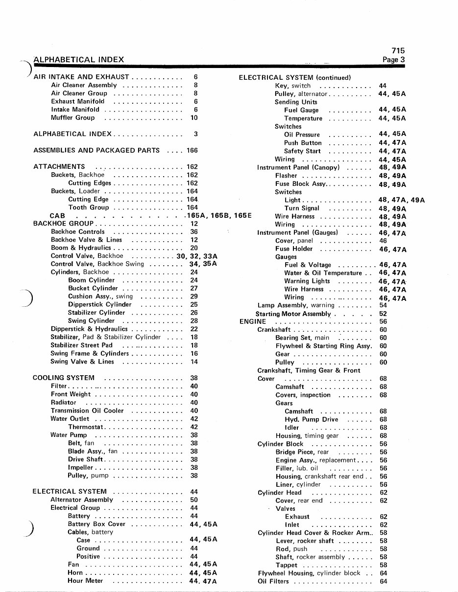
ALPHABETICAL INDEX 715 Page 3 AIR INTAKE AND EXHAUST 6 ELECTRICAL SYSTEM (continued) Air Cleaner Assembly 8 Key, switch 44 Air Cleaner Group 8 Pulley, alternator 44, 45A Exhaust Manifold 6 Sending Units Intake Manifold 6 Fuel Gauge 44, 45A Muffler Group 10 Temperature 44, 45A Switches ALPHABETICAL INDEX 3 Oil Pressure 44, 45A Push Button 44, 47A ASSEMBLIES AND PACKAGED PARTS . .. . 166 Safety Start 44; 47A Wiring 44, 45A ATTACHMENTS 162 Instrument Panel (Canopy) 48, 49A Buckets, Backhoe 162 Flasher 48, 49A Cutting Edges 162 Fuse Block Assy. 48, - 49A Buckets, Loader 164 Switches Cutting Edge 164. Light 48, 47A, 49A Tooth Group 164 Turn Signal 48, 49A CAB 165A, 165B, 165E Wire Harness 48, 49A BACKHOE GROUP 12 Wiring 48, 49A Backhoe Controls 36 Instrument Panel (Gauges) 46, 47A Backhoe Valve & Lines 12 Cover, panel 46 Boom & Hydraulics 20 Fuse Holder 46, 47A Control Valve, Backhoe 30, 32, 33A Gauges Control Valve, Backhoe Swing 34, 35A Fuel & Voltage 46, 47A Cylinders, Backhoe 24 Water & Oil Temperature 46, 47A Boom Cylinder 24 Warning Lights 46, 47A Bucket Cylinder 27 Wire Harness 46, 47A Cushion Assy., swing 29 Wiring 46, 47A Dipperstick Cylinder 25 Lamp Assembly, warning 54 Stabilizer Cylinder 26 Starting Motor Assembly . . 52 Swing Cylinder 28 ENGINE 56 Dipperstick & Hydraulics 22 Crankshaft 60 Stabilizer, Pad & Stabilizer Cylinder 18 Bearing Set, main 60 Stabilizer Street Pad 18 Flywheel & Starting Ring Assy. 60 Swing Frame & Cylinders 16 Gear 60 Swing Valve & Lines 14 Pulley 60 Crankshaft, Timing Gear & Front COOLING SYSTEM 38 Cover 68 Filter 40 Camshaft 68 Front Weight 40 Covers, inspection 68 Radiator 40 Gears Transmission Oil Cooler 40 Camshaft 68 Water Outlet 42 Hyd. Pump Drive 68 Thermostat 42 Idler 68 Water Pump 38 Housing, timing gear 68 Belt, fan 38 Cylinder Block 56 Blade Assy., fan 38 Bridge Piece, rear 56 Drive Shaft 38 Engine Assy., replacement. 56 Impeller 38 Filler, lub. oil 56 Pulley, pump 38 Housing, crankshaft rear end . 56 Liner, cylinder 56 ELECTRICAL SYSTEM 44 Cylinder Head 62 Alternator Assembly 50 Cover, rear end 62 Electrical Group 44 Valves Battery 44 Exhaust 62 Battery Box Cover 44, 45A Inlet 62 Cables, battery Cylinder Head Cover & Rocker Arm 58 Case 44, 45A Lever, rocker shaft . . .. .... 58 Ground 44 Rod, push 58 Positive 44 Shaft, rocker assembly 58 Fan 44, 45A Tappet 58 Horn 44, 45A Flywheel Housing, cylinder block 64 Hour Meter 44. 47A Oil Filters 64
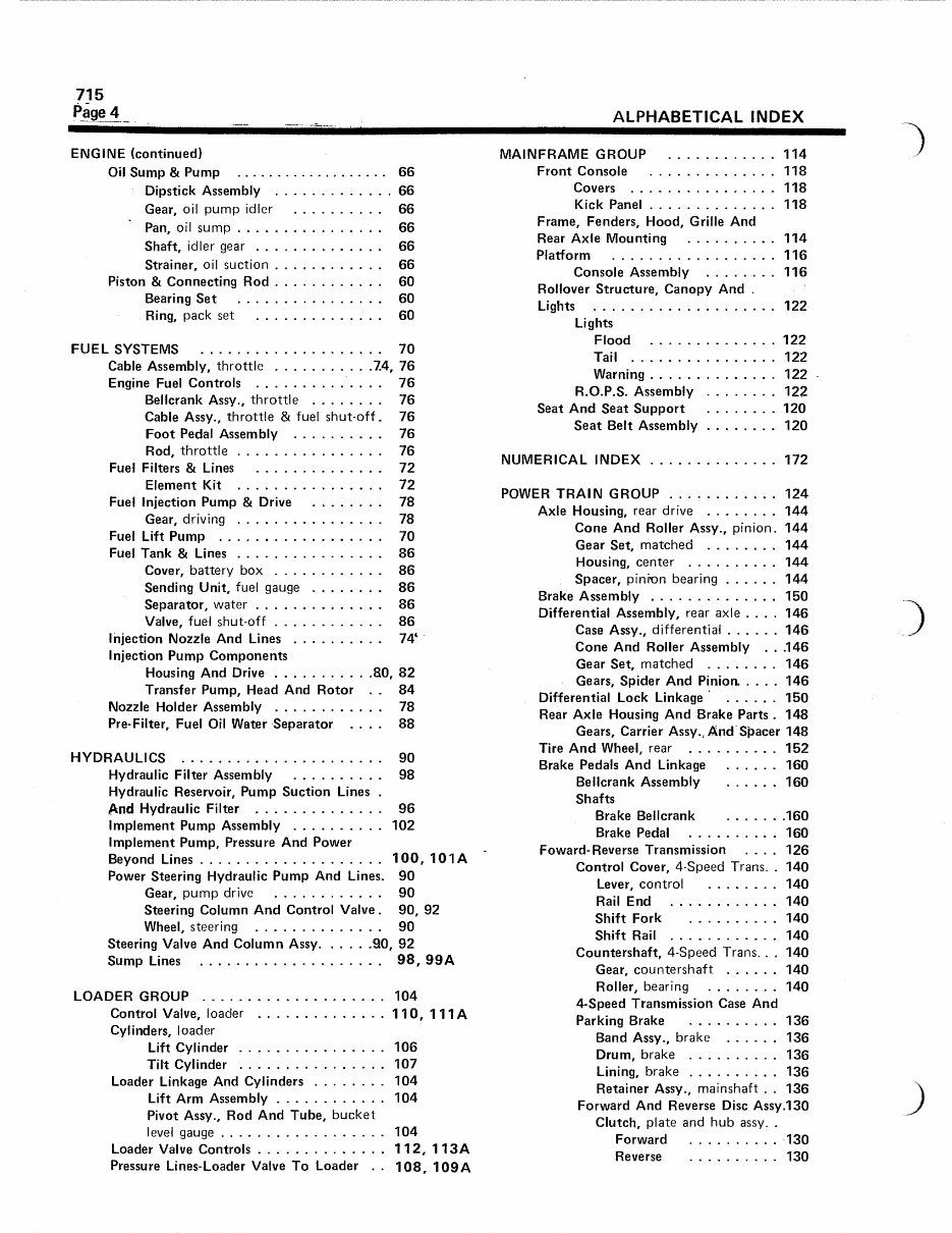
ALPHABETICAL INDEX 715 Page 4 ENGINE (continued) Oil Sump & Pump Dipstick Assembly Gear, oil pump idler Pan, oil sump Shaft, idler gear Strainer, oil suction Piston & Connecting Rod Bearing Set Ring, pack set FUEL SYSTEMS Cable Assembly, throttle Engine Fuel Controls Bellcrank Assy., throttle Cable Assy., throttle & fuel shut Foot Pedal Assembly Rod, throttle Fuel Filters & Lines Element Kit Fuel Injection Pump & Drive Gear, driving Fuel Lift Pump Fuel Tank & Lines Cover, battery box Sending Unit, fuel gauge Separator, water Valve, fuel shut-off Injection Nozzle And Lines Injection Pump Components Housing And Drive 80, 82 Transfer Pump, Head And Rotor . 84 Nozzle Holder Assembly 78 Pre-Filter, Fuel Oil Water Separator . 88 HYDRAULICS 90 Hydraulic Filter Assembly 98 Hydraulic Reservoir, Pump Suction Lines And Hydraulic Filter 96 Implement Pump Assembly 102 Implement Pump, Pressure And Power Beyond Lines 100, 101A Power Steering Hydraulic Pump And Lines. 90 Gear, pump drive 90 Steering Column And Control Valve 90, 92 Wheel, steering 90 Steering Valve And Column Assy. 90, 92 Sump Lines 98, 99A LOADER GROUP 104 Control Valve, loader 110, 1 1 1 A Cylinders, loader Lift Cylinder 106 Tilt Cylinder 107 Loader Linkage And Cylinders 104 Lift Arm Assembly 104 Pivot Assy., Rod And Tube, bucket level gauge 104 Loader Valve Controls 112, 1 1 3 A Pressure Lines-Loader Valve To Loader . 108, 1 0 9A MAINFRAME GROUP 114 Front Console 118 Covers 118 Kick Panel 118 Frame, Fenders, Hood, Grille And Rear Axle Mounting 114 Platform 116 Console Assembly 116 Rollover Structure, Canopy And Lights 122 Lights Flood 122 Tail 122 Warning 122 - R.O.P.S. Assembly 122 Seat And Seat Support 120 Seat Belt Assembly 120 NUMERICAL INDEX 172 POWER TRAIN GROUP 124 Axle Housing, rear drive 144 Cone And Roller Assy., pinion 144 Gear Set, matched 144 Housing, center 144 Spacer, pinion bearing 144 Brake Assembly 150 Differential Assembly, rear axle ... 146 Case Assy., differential 146 Cone And Roller Assembly . .146 Gear Set, matched 146 Gears, Spider And Pinion 146 Differential Lock Linkage • 150 Rear Axle Housing And Brake Parts 148 Gears, Carrier Assy., And - Spacer 148 Tire And Wheel, rear 152 Brake Pedals And Linkage 160 Bellcrank Assembly 160 Shafts Brake Bellcrank 160 Brake Pedal 160 Foward-Reverse Transmission . . . 126 Control Cover, 4-Speed Trans. 140 Lever, control 140 Rail End 140 Shift Fork 140 Shift Rail 140 Countershaft, 4-Speed Trans.. 140 Gear, countershaft 140 Roller, bearing 140 4-Speed Transmission Case And Parking Brake 136 Band Assy., brake 136 Drum, brake 136 Lining, brake 136 Retainer Assy., mainshaft . 136 Forward And Reverse Disc Assy.130 Clutch, plate and hub assy. Forward 130 Reverse 130 66 66 66 66 66 66 60 60 60 70 74, 76 76 76 -off . 76 76 76 72 72 78 78 70 86 86 86 86 86
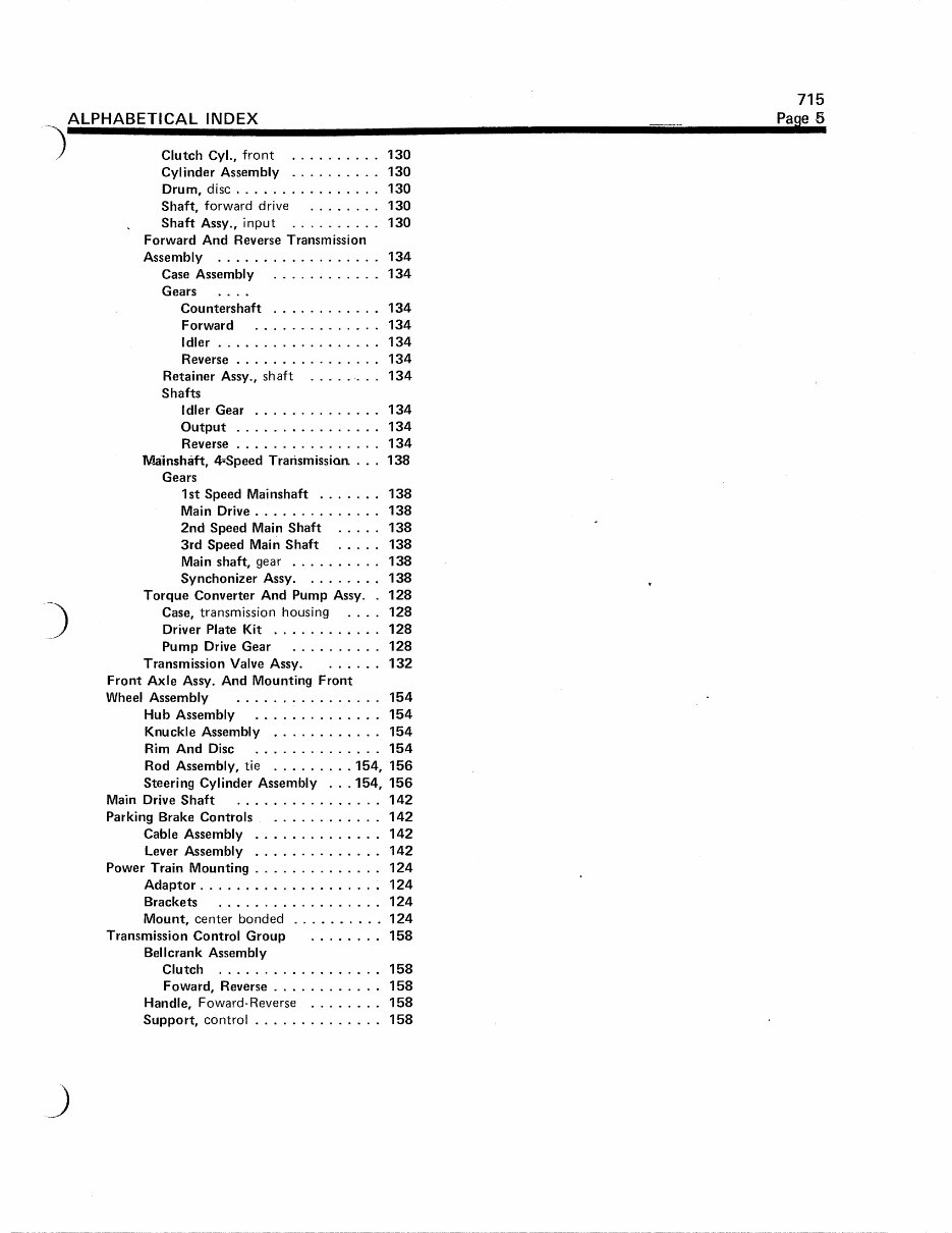
715 ALPHABETICAL INDEX Pa se 5 Clutch Cyl., front 130 Cylinder Assembly 130 Drum, disc 130 Shaft, forward drive 130 Shaft Assy., input 130 Forward And Reverse Transmission Assembly 134 Case Assembly 134 Gears . . Countershaft 134 Forward 134 Idler 134 Reverse 134 Retainer Assy., shaft 134 Shafts Idler Gear 134 Output 134 Reverse 134 Mainshaft, 4=Speed Transmission. 138 Gears 1st Speed Mainshaft 138 Main Drive 138 2nd Speed Main Shaft 138 3rd Speed Main Shaft 138 Main shaft, gear 138 Synchonizer Assy. 138 Torque Converter And Pump Assy. 128 Case, transmission housing . . . 128 Driver Plate Kit 128 Pump Drive Gear 128 Transmission Valve Assy. 132 Front Axle Assy. And Mounting Front Wheel Assembly 154 Hub Assembly 154 Knuckle Assembly 154 Rim And Disc 154 Rod Assembly, tie 154, 156 Steering Cylinder Assembly . . 154, 156 Main Drive Shaft 142 Parking Brake Controls 142 Cable Assembly 142 Lever Assembly 142 Power Train Mounting 124 Adaptor 124 Brackets 124 Mount, center bonded 124 Transmission Control Group 158 Bellcrank Assembly Clutch 158 Foward, Reverse 158 Handle, Foward-Reverse 158 Support, control 158
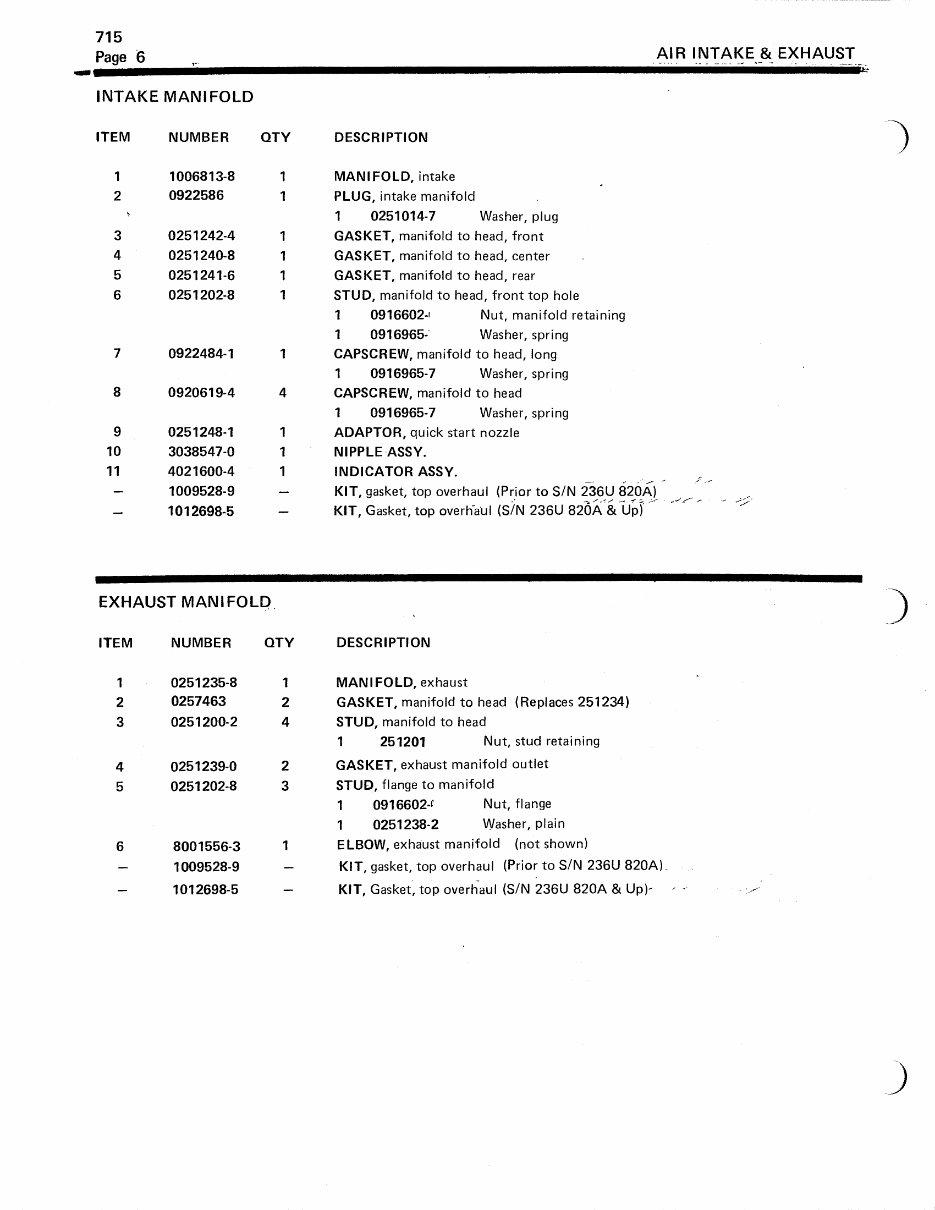
715 Page 6 AIR INTAKE & EXHAUST INTAKE MANIFOLD ITEM NUMBER QTY DESCRIPTION 1 1006813-8 1 MANIFOLD, intake 2 0922586 1 PLUG, intake manifold 1 0251014-7 Washer, plug 3 0251242-4 1 GASKET, manifold to head, front 4 0251240-8 1 GASKET, manifold to head, center 5 0251241-6 1 GASKET, manifold to head, rear 6 0251202-8 1 STUD, manifold to head, front top hole 1 0916602-i Nut, manifold retaining 1 0916965- Washer, spring 7 0922484-1 1 CAPSCREW, manifold to head, long 1 0916965-7 Washer, spring 8 0920619-4 4 CAPSCREW, manifold to head 1 0916965-7 Washer, spring 9 0251248-1 1 ADAPTOR, quick start nozzle 10 3038547-0 1 NIPPLE ASSY. 11 4021600-4 1 INDICATOR ASSY. — 1009528-9 — KIT, gasket, top overhaul (Prior to S/N 236U 820A) — 1012698- 5 — KIT, Gasket, top overliaul (S/N 236U 820A & Up) EXHAUST MANIFOLD, ITEM NUMBER QTY DESCRIPTION 1 0251235-8 1 MANIFOLD, exhaust 2 0257463 2 GASKET, manifold to head (Replaces 251234) 3 0251200-2 4 STUD, manifold to head 1 251201 Nut, stud retaining 4 0251239-0 2 GASKET, exhaust manifold outlet 5 0251202-8 3 STUD, flange to manifold 1 0916602-c Nut, flange 1 0251238-2 Washer, plain 6 8001556-3 1 ELBOW, exhaust manifold (not shown) — 1009528-9 — KIT, gasket, top overhaul (Prior to S/N 236U 820A). — 1012698-5 — KIT, Gasket, top overhaul (S/N 236U 820A & Up)-
- L abed 9LL
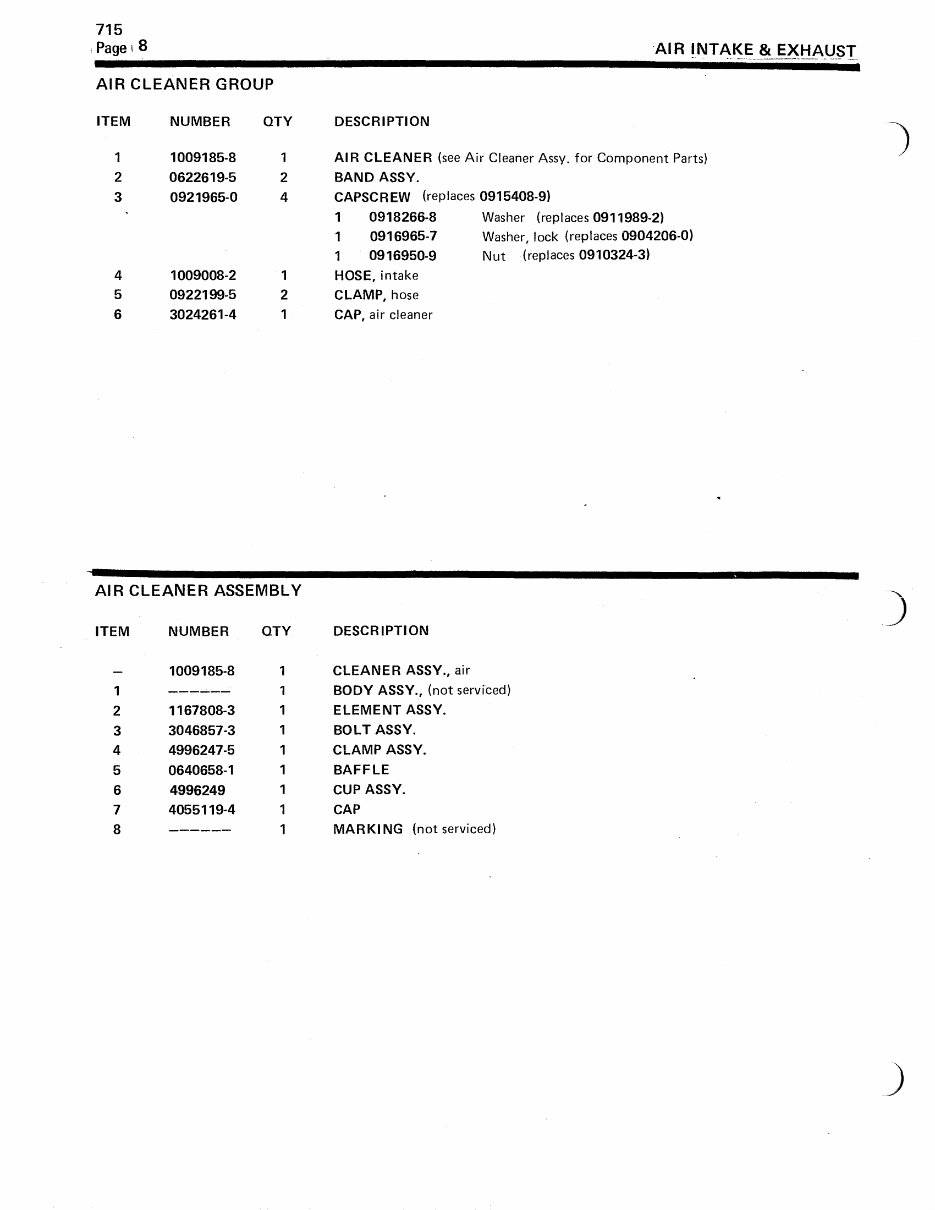
715 Pagel8 AIR INTAKE & EXHAUST AIR CLEANER GROUP ITEM NUMBER QTY DESCRIPTION 1 1009185-8 1 AIR CLEANER (see Air Cleaner Assy. for Component Parts) 2 0622619-5 2 BAND ASSY. 3 0921965-0 4 CAPSCREW (replaces 0915408-9) 1 0918266-8 Washer (replaces 0911989-2) 1 0916965-7 Washer, lock (replaces 0904206-0) 1 0916950-9 Nut (replaces 0910324-3) 4 1009008-2 1 HOSE, intake 5 0922199-5 2 CLAMP, hose 6 3024261-4 1 CAP, air cleaner AIR CLEANER ASSEMBLY ITEM NUMBER QTY DESCRIPTION — 1009185-8 1 CLEANER ASSY., air 1 1 BODY ASSY., (not serviced) 2 1167808-3 1 ELEMENT ASSY. 3 3046857-3 1 BOLT ASSY. 4 4996247-5 1 CLAMP ASSY. 5 0640658-1 1 BAFFLE 6 4996249 1 CUP ASSY. 7 4055119-4 1 CAP 8 1 MARKING (not serviced)
This Parts Catalog Manual is an essential resource for anyone working with the Allis Chalmers 715 Backhoe Loader. It features high-quality diagrams and detailed instructions for servicing and repairing your equipment. Whether you're a professional mechanic or a DIY enthusiast, this manual is a valuable tool that can help you save on service, repair, and maintenance costs.
The manual covers the following model:
715 Backhoe-Loader
With instant access upon payment, there are no shipping costs or waiting for a CD to arrive. This means you can receive the manual today through instant download. Accepted payment methods include all major credit/debit cards and PayPal.
File Format: PDF
Compatibility: All Versions of Windows & Mac, APP ISO, iPhone, iPod, Android, etc.
Language: English
Requirements: Adobe Reader
Don't miss out on the opportunity to enhance your understanding of your Allis Chalmers equipment and save on maintenance costs. Purchase and download the manual now!
Recently Viewed
5,521,897Happy Clients
2,594,462eManuals
1,120,453Trusted Sellers
15Years in Business
Price:
Actual Price:
Allis Chalmers 715 Backhoe Loader Parts Catalog Manual