

1999 Volvo V70 Service & Repair Manual
What's Included?
Fast Download Speeds
Offline Viewing
Access Contents & Bookmarks
Full Search Facility
Print one or all pages of your manual

2.3L & 2.4L 5-CYL & 2.9L 6-CYL
Article Text
1998 Volvo V70
For 1
Copyright © 1998 Mitchell Repair Information Company, LLC
Wednesday, November 10, 2010 04:41AM
ARTICLE BEGINNING
1997-98 ENGINES
Volvo 2.3L & 2.4L 5-Cylinder & 2.9L 6-Cylinder
1997: 850, 960
1998: C70, S70, V70, S90, V90
* PLEASE READ THIS FIRST *
NOTE: For engine repair procedures not covered in this article,
see ENGINE OVERHAUL PROCEDURES - GENERAL INFORMATION article
in the GENERAL INFORMATION section. Repair information for
this engine is not available from manufacturer.
ENGINE IDENTIFICATION
Engine may be identified by using Vehicle Identification
Number (VIN) stamped on a metal pad located near lower left corner of
windshield. The sixth and seventh character identifies engine model.
Engine identification number, located on left side of
cylinder block below cylinder head, may be required when ordering
replacement parts.
ENGINE IDENTIFICATION CODES
Engine Code Engine Type
52 (2.3L DOHC) ......................................... (1) B5234T6
53 (2.3L DOHC) ......................................... (1) B5234T3
55 (2.4L DOHC) .............................................. B5254S
56 (2.4L DOHC) .......................................... (2) B5254T
57 (2.4L DOHC) .......................................... (1) B5234T
96 (2.9L DOHC) ............................................... 6304S
(1) - High pressure turbo.
(2) - Low pressure turbo.
ADJUSTMENTS
VALVE CLEARANCE ADJUSTMENT
Engine is equipped with hydraulic lifters. No valve
adjustment is necessary.
REMOVAL & INSTALLATION
* PLEASE READ THIS FIRST *
2.3L & 2.4L 5-CYL & 2.9L 6-CYL Article Text (p. 2)
1998 Volvo V70For 1
Copyright © 1998 Mitchell Repair Informatio
NOTE: For reassembly reference, label all electrical connectors,
vacuum hoses and fuel lines before removal. Also place
mating marks on other major assemblies before removal. Hood
removal is not necessary, as hood opens to horizontal
position. Removal and installation information for
turbocharger is not available from manufacturer.
FUEL PRESSURE RELEASE
Fuel Pump Pressure Release
1) Unplug fuel pump relay. Start engine and run until engine
stalls. Crank engine an additional 3 seconds.
2) Before disconnecting any lines, cover fuel line connector
with shop towel to absorb any fuel left in line. With ignition key
removed from ignition switch, reconnect fuel pump relay.
ENGINE
Removal (5-Cylinder)
1) Remove expansion tank cap. Raise and support vehicle.
Remove splash guard and air baffle under engine. Drain all coolant by
opening drain cocks on cylinder block and radiator. Remove front
wheels, steering arm/wheel spindle joints, and nuts securing ball
joints to support arms.
2) Remove ABS wire and brake line retaining bracket bolt
located on inner fender panel, close to bottom of strut. Remove left
axle shaft. See AXLE SHAFTS - FRONT article in DRIVE AXLES. Disconnect
2 thin, Black hoses from evaporative fuel canister. Remove White
vacuum hose from vacuum reservoir.
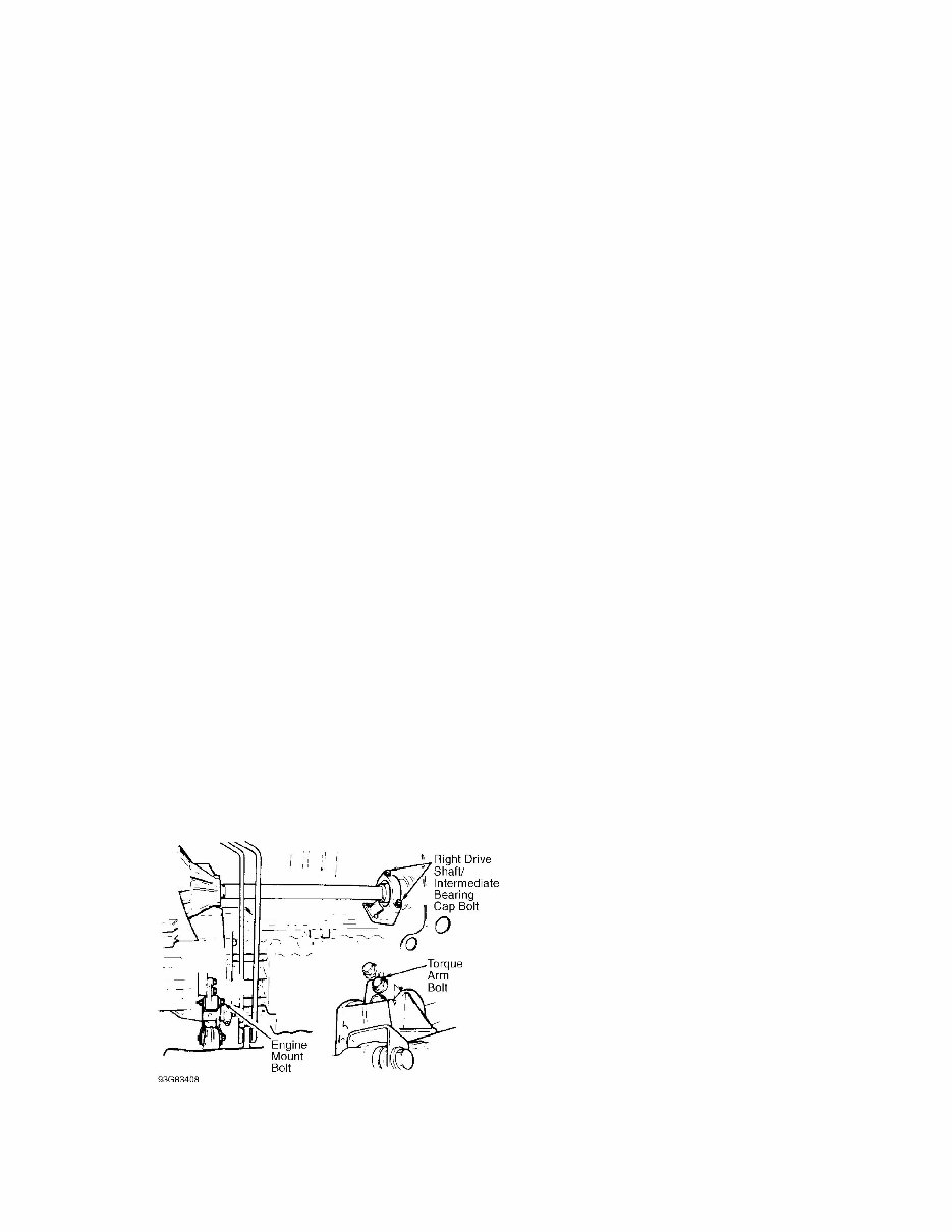
3) Remove right axle shaft and intermediate bearing cap.
Carefully place components on steering servo pipes. Remove 2 right
engine mounting bolts. Loosen wheel arch liner to allow access to
mounting. Remove torque arm in gearbox. See Fig. 1. Install Sealing
Plugs (5488) in axle shaft holes.
Fig. 1: Removing Drive Shaft, Engine Mount Bolt & Torque Arm (5-
Cylinder)
Courtesy of Volvo Cars of North America.
4) Remove front exhaust pipe nuts and springs. Remove front

2.3L & 2.4L 5-CYL & 2.9L 6-CYL Article Tex
exhaust pipe bolts. Disconnect speedometer. Remove engine mounting
shield bolt. Lower vehicle.
5) Remove battery, battery self, and fresh air hose between
air intake and air cleaner housing. Disconnect MAF sensor connector
and primary lead between distributor and coil. Remove throttle pulley
cover. If equipped with cruise control, disconnect all necessary
electrical wiring and vacuum hose.
6) Disconnect intake hose at throttle body and idle air
control valve hose. Disconnect vacuum hose and crankcase ventilation
hose from intake hose. Disconnect vacuum hoses and connector from
solenoid valve. Disconnect heater hose. Remove air cleaner housing.
Disconnect throttle cable from throttle pulley. Remove torque arm.
7) Disconnect 2 heater hoses at firewall, brake servo hose,
and 2 HO2S connectors. Remove upper nut on rear engine mount.
Disconnect gear selector cables from mounting bracket on transmission.
Disconnect rubber-mounted section of cable bracket. On automatic
transmission equipped vehicles, disconnect 2 oil cooler hoses. On
manual transmission equipped vehicles, remove clutch slave cylinder
retaining ring. Remove slave cylinder from transmission.
8) On all vehicles, disconnect negative battery cable.
Disconnect lower radiator hose at radiator. Loosen and move air
cleaner mounting bracket aside. Remove rubber mount from air cleaner
bracket. On manual transmission equipped vehicles, remove clutch slave
cylinder through front hole in air cleaner bracket and place aside. On
all vehicles, place air cleaner bracket aside.
9) Remove electric cooling fan relays from fan shroud.
Disconnect connectors and place wiring aside. Remove 2 control module
box cooling air ducts. Remove 4 fan shroud screws from radiator. Use a
piece of plywood to protect radiator and slide fan housing back
slightly and remove air intakes. Remove fan.
10) Remove 2 long mounting bolts in A/C compressor. Leave
compressor in position until removing engine. Remove front engine
mounting pad nut and cable duct bracket mounting bolts. Remove intake
manifold and starter support brackets.
11) Disconnect upper radiator hose from thermostat housing.
Remove coolant hose between expansion tank and thermostat housing.
Remove expansion tank lower hose from fitting on engine. Remove drive
belt. Disconnect temperature sensor wiring from bracket on servo pump.
Remove 6 servo pump bolts. Leave servo pump in position at this time.
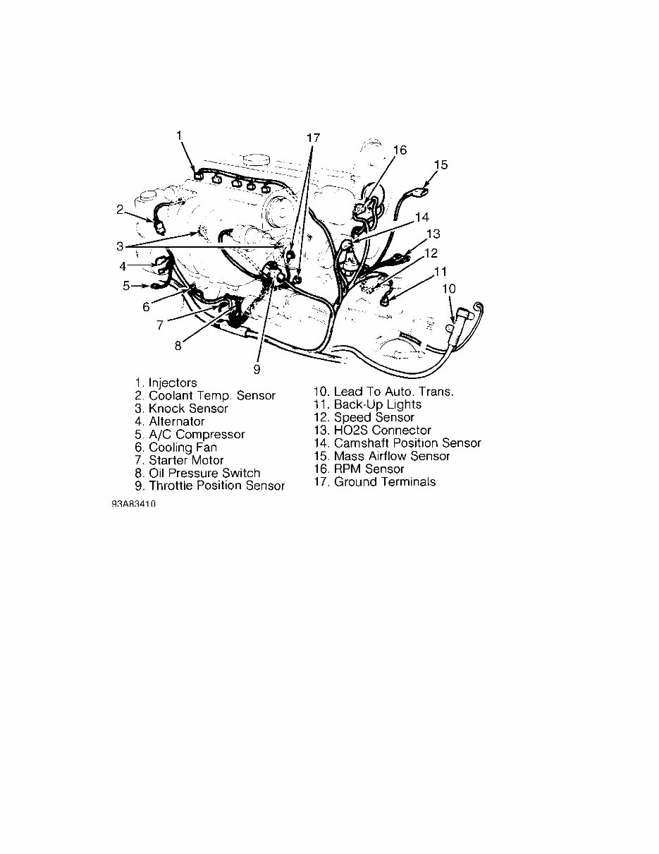
12) Remove protective cover over fuel distribution manifold.
Remove upper and lower fuel pipe clips. Remove fuel distribution
manifold bolts. Disconnect braided ground lead from engine. Secure
injectors with 5 Holders (5465). Lift and place fuel distribution
manifold (including injectors) aside. Remove engine wiring harness.
See Fig. 2.
2.3L & 2.4L 5-CYL & 2.9L 6-CYL Article Text (p. 4)
1998 Volvo V70For 1
Copyright © 1998 Mitchell Repair Informatio
Fig. 2: Removing Engine Wiring Harness (5-Cylinder)
Courtesy of Volvo Cars of North America.
13) Remove spark plug cover and attach Lifting Lugs (5459 and
5464) to engine. Lift servo pump and place aside. Remove A/C
compressor and place on sub-frame. Lift out engine and transmission
using Lifting Yokes (2810 and 5428).
Removal (6-Cylinder)
1) Place hood in vertical position. Disconnect battery.
Remove ground lead connection to body at top side member. Remove clip
on side member. Remove battery. Remove auxiliary drive belt. Remove
cooling fan and drain coolant.
2) Disconnect upper and lower coolant hoses from engine.
Disconnect expansion tank hose from radiator and return pipe.
Disconnect cooling lines from radiator.
3) Remove top nut from both left and right engine mounts.
Remove air mass meter and intake hose. Disconnect and remove large and
small crankcase ventilation hoses, idling hose and idling valve lead.
4) Remove 2 EVAP valve hoses at intake manifold. Remove air
mass meter connector, air preheater hose and throttle pulley cover.
Remove 3 bolts at front of servo pump and 2 at rear of servo pump.
Remove servo pump.

2.3L & 2.4L 5-CYL & 2.9L 6-CYL Article Text (p. 5)
1998 Volvo V70For 1
Copyright © 1998
5) Disconnect fuel return line at regulator. Remove fuel line
at bulkhead. Remove throttle cable. Remove cruise control vacuum hose.
Remove fuel line snap catches. Remove engine wiring harness cover and
disconnect connector. Remove harness duct mounting nuts.
6) Disconnect 2 cooling hoses from firewall. Remove 2 ECC
hoses at intake manifold. Remove camshaft sensor, timing pick-up and
brake servo vacuum line. To support engine, use 2 Support Rails
(5033), Lifting Beam (5006), Lifting Hook (5115) and Lifting Yoke
(5428). Attach Lifting Lug (5429) to rear of engine. Support engine.
7) Remove splash guard and air baffle under engine. Loosen 2
radiator mounting bolts. Drain engine oil. Disconnect oil thermostat
hoses at thermostat in cylinder block. Remove 2 air conditioner
compressor mounting bolts and disconnect electrical connector. Remove
compressor and lay aside.
8) Loosen exhaust pipe flanges at manifold. Remove lower
section of air preheater pipe. Remove exhaust pipe shield. Remove oil
cooler lines at transmission. Disconnect gear selector lever from
transmission.
9) Disconnect oxygen sensor wiring. Mark propeller shaft for
reassembly reference. Disconnect propeller shaft and remove
transmission support member. Place jack under transmission and remove
all lifting tools. Remove radiator attaching bolts. Lift out radiator
and transmission fluid cooling lines.
10) Using Lifting Tool (2810), lift engine from vehicle.
Remove jack from under transmission.
Installation (5-Cylinder & 6-Cylinder)
1) Attach Lifting Lug (5429) to rear of engine. Using Lifting
Yoke (5428) and Lifting Tool (2810), lower engine and transmission
into position. Guide engine mountings into position and tighten top
nuts to 37 ft. lbs. (50 N.m).
2) Support transmission with floor jack, and remove lifting
yoke from engine. Using 2 Support Rails (5033), Lifting Beam (5006)
and Lifting Hook (5115), support rear of engine. Remove jack under
transmission. Using Transmission Lifting Fixture (5972), raise
transmission. Install transmission support member. Tighten bolted
joints between support member and side members. Tighten transmission
bump stop nut to specification. See TORQUE SPECIFICATIONS.
3) Install control rod and reaction arm to lever mounting.
Install locking clip. Install oxygen sensor and reconnect electrical
connector. Using Socket (5244), tighten front and rear couplings.
Ensure "O" ring is okay and install air preheater pipe to exhaust
pipe.
4) Install air conditioning compressor to mounting. Reconnect
oil cooler lines. Tighten fittings to 26 ft. lbs. (35 N.m). Remove
lifting tools.
5) Reinstall coolant hoses to firewall. Install timing pick-
up and camshaft sensor connectors. Reconnect engine connector to
wiring harness connector on left wheel housing. Reconnect relay and
install wiring duct mounting nuts. Install harness connector cover.
6) Install fuel hoses, cruise control vacuum hose, ECC vacuum
hoses, brake servo vacuum hose, throttle cable and throttle pulley
You're Reading a Preview
What's Included?
Fast Download Speeds
Offline Viewing
Access Contents & Bookmarks
Full Search Facility
Print one or all pages of your manual
$37.99
$49.99
Viewed 67 Times Today


Secure transaction
What's Included?
Fast Download Speeds
Offline Viewing
Access Contents & Bookmarks
Full Search Facility
Print one or all pages of your manual
$37.99
$49.99
Introducing the 1999 Volvo V70 Service & Repair Manual:
- Comprehensive guide for maintaining and fixing your 1999 Volvo V70
- Covers a wide range of service and repair procedures to keep your vehicle running smoothly
- Written by expert technicians with years of experience
- Includes detailed instructions, diagrams, and illustrations to assist you in every step
- Designed specifically for the 1999 Volvo V70 models:
- 1999 Volvo V70 Base
- 1999 Volvo V70 GLT
- 1999 Volvo V70 AWD
- 1999 Volvo V70 XC
- Save money on costly repairs by performing them yourself
- Perfect for DIY enthusiasts and professional mechanics alike
- Ensure the longevity and reliability of your 1999 Volvo V70
- Invest in the 1999 Volvo V70 Service & Repair Manual today!


