Cars with SRS (Air bag)/SIPS bag Wa rning Cars equipped with a Supplemental Restraint System (SRS)/SIPS bag must be treated extra carefully when repairs are being made. This is to help prevent 1. Injuries when carrying out a repai r. 2. Damage or malfunction of the SRS/SIPS bag system Repair to either the SRS/SIPS bag itself or a related system or component must be carried out by an authorized Volvo workshop. Refer to the appropriate SRS and SIPS bag service manual for complete system information Is I he car equipped wi lh SRS ? Cars with SRS are most easily recognized by the SRS letters on thesteering wheel pad. If the car is also equipped with an air bag on ihe passenger side , the letters 'SRS' wifl be embossed on the instrument panel above the glove compartmen t. On models from 1993 on , cars with SRS will als。 be equipped with pyrotechnical seat belt tensioners in the B-posts The SIPS bags are only installed in cars equipped with SRS systems , 1995- . Cars with SIPS bags can be recog-nized by the identifying labels on the windshield and on seat storage tray Dashboa rd or around Sleer i ng colum r、 Tak~ car e.. to avoid the SRS .wiring being pinched , frayed or pierced by screws when working on the firewall , knee bolster , ignition switch: steering column casings , glove compartme 时, ìnslrument panel , door sills and B-posts Cenler consol e The SRS collision sensor is located between the handbrake and gear lever (selector) in the center console. Never install accessories on or near the sensor Repai rs 10 sleering gear and column 312J331;但 ;111:lzp;li;tgggZJElAZr3 斗 ttZA;5tJl111:21:1427JAI will be damaged if the steering wheel is turned more than three turns in either direction Seals The SIPS bag sensor is located in the front section of the seat storage tray. The SIPS-bag can be activated by a blow or pressure on the tray or if an object is caught between the tray and the door when the dòor is closed. Refer to the SIPS-bag Service manual when carrying out work on the front seats Tesl lermi na l Data Li nk Connector socket in passenger compartment Modif i cations i nlroduced Up 10 and i ncluding March 1 998 Any modifications made to the car after this date are not included in this manual See Service Bulletin if necessary Volvos are sold in versions adapted for different markets. These adaptations depend on many factors including legal , taxation and market requirements. This manual may therefore show illustrations and text which do not apply to cars in your count叩 。 Volvo Car Corporalion
1 How to use the diagrams ................................................................ 2 Fuses ............................................................................................... 4 Rails in the central electrical unit .................................................... 7 Ignition switch .................................................................................. 7 Relays .............................................................................................. 8 Ground terminals ............................................................................. 10 Electrical distribution ....................................................................... 14 Connectors ...................................................................................... 16 Junction points ................................................................................. 48 Routing of cable harnesses in the car ............................................. 65 Group 23/28 Ignition and fuel injection system .................................................... 72 Group 26 Engine cooling fan (FC) ................................................................... 76 Group 27 Cruise control .................................................................................. 78 Group 32/33 Power supply and starter system .................................................... 80 Group 35 Fog lamps ........................................................................................ 82 Parking lamps, tail lamps and license (number) plate lighting .................................................................................... 84 Stop (brake) lamps .......................................................................... 86 Back-up (reversing) lamps ............................................................... 88 Interior lighting ................................................................................. 90 Instrument and control lighting ........................................................ 92 Group 36 Turn signal lamp and hazard warning signal flashers ............................................................................................ 94 Cigarette lighter / 12V-output ........................................................... 96 Anti-theft alarm ................................................................................ 98 Immobilizer ...................................................................................... 100 Group 38 Seat belt reminder and ignition key warning ................................... 102 Combined instrument panel ............................................................ 104 Group 39 Radio ............................................................................................... 110 RTI Road Traffic Information ............................................................ 112 Group 43 Electronically controlled automatic transmission AW 50-42 ......................................................................................... 114 Group 83 Power windows ................................................................................ 116 Central locking ................................................................................. 118 Soft-top operation ............................................................................ 122 Group 84 Heated rear window and heated door mirrors ......................................................................... 126 Power door mirrors .......................................................................... 128 Group 85 Electrically heated seats .................................................................. 130 Power seats ..................................................................................... 132 Group 87 Manual Climate Control MCC .......................................................... 134 Electronic climate control ECC ........................................................ 136 Group 88 Roll over protection ROPS .............................................................. 138 SRS Supplemental Restraint System .............................................. 140 Rear view mirror with automatic dimming ....................................... 142 Index ................................................................................................ 144 Component list (fold-out) ........................................ see end of manual Follow-ups ...................................................... last page of this manual Contents Order number TP3937202 Supersedes book TP 3937201 We reserve the right to make alterations without prior notification This book covers the electronic functions that are particular to the 1998 model year C70 convertible. The Service Manual TP3932202 can be used for the remainder of the electrical system.
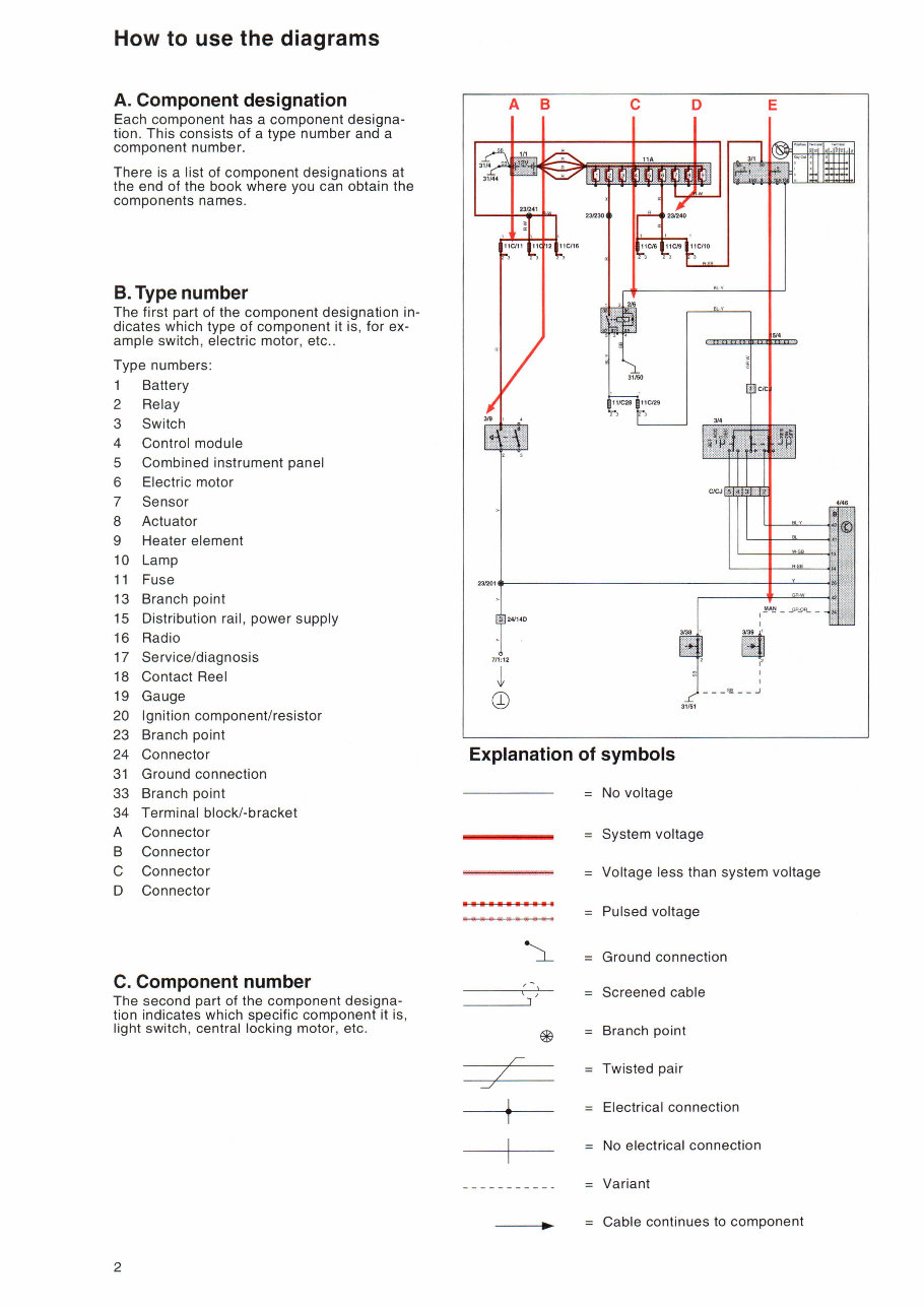
How to use the diagrams A. Component designation Each component has a component designa- tion. This consists of a type number and a component numbe r. There is a list of component designations at the end of the book where you can obtain the components names B. Type number The first part of the component designation in - dicates which type of component it is , for ex- ample switch , electric motor , etc.. Type numbers: Battery 2 Relay 3 Switch 4 Control module 5 Combined instrument panel 6 Electric motor 7 Sensor 8 Actuator 9 Heater element 10 Lamp 11 Fuse 13 Branch point 15 Distribution rail , power supply 16 Radio 17 Service/diagnosis 18 Contact Reel 19 Gauge 20 Ignition componen tJ resistor 23 Branch point 24 Connector 31 Ground connection 33 Branch point 34 Terminal block/-bracket A Connector B Connector C Connector D Connector C. Component number The second part of the component designa- tion indicates which specific component it is , light switch , central locking motor , etc. 2 A B E c D 231201 ① !'''~ _ .s-先归- - 3139 1 1 打句老1'1 F _ __ 5.且 - - -' Explanation of symbols t主L No voltage System voltage Voltage less than system voltage Pulsed voltage Ground connection e | 』Ua C AU e n e e vl C QU -J /- / -./ T ( Branch point Twisted pair Electrical connection No electrical connection Variant 一一一一一.. Cable continues to component
Get instant access to the 1998 Volvo C70 Convertible Electrical Wiring Diagram Manual. This electronic manual offers a clear advantage over its paper counterpart, allowing you to zoom in on any section for enhanced visibility on your computer. It covers a wide range of electrical components and systems, making it an essential resource for both professional mechanics and DIY enthusiasts.
The manual includes detailed information on electrical distribution, fuses, relays, ground connections, control modules, engine management system, electric cooling, cruise control, charging and starting circuits, lighting systems, power accessories, diagnostics, and more. Each section is written in a step-by-step format, enabling easy and cost-effective repairs.
File Format: PDF
Compatibility: All Versions of Windows & Mac
Language: English
Requirements: Adobe Reader & Win