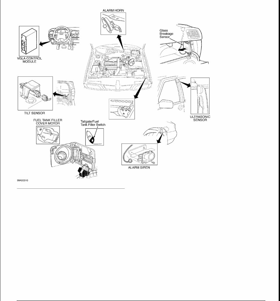
1999 ACCESSORIES & EQUIPMENT Anti-Theft & Power Door Lock Systems DESCRIPTION & OPERATION Volvo Guard Lock and Alarm (VGLA) system contains a control module capable of controlling the functions of the alarm, the central locking system (power door locks), courtesy light and blower motor. Door key on driver's side has lock/unlock functions, as well as the ability to arm/disarm the anti-theft system in case of lost or damaged remote controls. Passenger's door lock cylinder is no longer available. Rotate driver's door lock key once to unlock driver's door only. Rotate driver's door key a second time within 10 seconds, and all doors and the trunk/tailgate will unlock. Alarm system is activated by depressing LOCK button on remote control or by locking driver's front door or trunk using standard door keys. Central locking system's remote control, setting device and lock cylinder micro- switches send signals to central locking relay, which in turn sends a control signal to alarm control module. When alarm is armed using lock button on remote control, the indicator lights (parking lights) will flash once. When alarm is disarmed using unlock button on remote control, indicator lights will flash twice. After 5 seconds of arming alarm with either key or remote control, LED indicator goes out and starts flashing. This indicates that alarm has been activated. If hood, trunk or any door is open when system is activated, LED will not illuminate. When doors, hood and trunk are closed, LED will start flashing to indicate that all alarm loops have been activated. Alarm is protected by input signals from standard door contacts, contact on hood catch, contacts on rear window, level sensor, glass break sensor and ultrasound sensors. Alarm controls output signals to starter immobilizer, indicator lights and siren. See Fig. 1 . Remote control will not function until ignition key is removed from ignition switch lock cylinder. If no door is opened within 2 minutes of depressing the unlock button, doors will automatically lock. Another function of the VGLA module is activating the blower motor to dry the evaporator. If the A/C compressor has been activated for more than 4 minutes and the ignition switch is turned off, the VGLA control module activates blower motor after 50 minutes to dry evaporator core for 5 minutes to prevent odors from accumulating. When the fan is activated, the VGLA control module ignores signals from the ultrasonic sensors. Normally the movement of the air inside the vehicle would trigger the alarm system. NOTE: Information on S80 was not available from manufacturer. Wiring diagrams are include for aiding diagnosis. WARNING: Deactivate air bag system before performing any service operation. See AIR BAG RESTRAINT SYSTEMS article. DO NOT apply electrical power to any component on steering column without first deactivating air bag system. Air bag may deploy.
Fig. 1: Identifying Alarm System Components Courtesy of VOLVO CARS OF NORTH AMERICA ALARM HORN/SIREN C70 Alarm is equipped with either an alarm horn or siren. Horn is located in engine compartment on firewall beside upper engine mounting. Siren is located on right front wheelwell. GLASS BREAK SENSOR C70 Glass break sensor is located on the passenger side of the dashboard, near the speaker. The glass break sensor uses a microphone and control module tuned to frequencies of breaking glass. If the proper frequencies are "heard", a signal is sent to the VGLA control module to trigger alarm system. On station wagons, the 3 rear windows have metal wire integrated into glass that sends a signal to VGLA module if severed. The glass break sensor communicates with the VGLA module through a serial data line. Glass break sensor is an input signal.
MOVEMENT SENSOR On C70 coupe and cabriolet, if equipped with an alarm, are equipped with a mass movement sensor and no ultra sound or glass break sensors. RESISTIVE WIRE C70 Resistive wire are located in rear windows of 5-door models and are identified by an additional wire, in addition to antenna wire, in rear windows. TILT SENSOR C70 Tilt sensor is located behind right rear wheelwell (under passenger side of dashboard on all-wheel drive models). The tilt sensor discriminates between the car rocking or if the car is being lifted up (jacked up, hooked up to a tow truck). The sensor must be at a constant angle before a signal is sent to the VGLA module to trigger alarm. If the tilt sensor angle is intermittent, the tilt sensor will ignore the movement. The tilt sensor communicates with the VGLA module through a serial data line. Tilt sensor is an input signal. SIREN Siren is located in right front wheelwell. The siren has a built-in control module and back-up battery. The battery is charged when ignition switch is in ON position. When alarm is armed, if wiring to siren is cut or battery voltage drops off (battery disconnected), the siren will sound under power from back-up battery (up to 5 minutes if battery is fully charged). If alarm is not armed, then siren does not respond. The horn works along with the siren when the alarm is triggered. The siren communicates with the VGLA module through a serial data line. Siren is an output signal. ULTRASOUND SENSORS There are 2 ultrasound sensors (master-left, slave- right) in the alarm system. The ultrasound sensors are located in the "B" pillars. Each sensor consists of a control module with 2 integrated receivers/transmitters. One sensor points toward the front of the vehicle, the other sensor points to the rear. Sensors transmit sound-waves of a given frequency and read frequency of sound waves that bounce back. Sensors detect movement in vehicle through variation in frequencies that are bounced back and send signals to VGLA module to trigger alarm. Sensors are very sensitive to subtle changes such as air movement through an open window or sunroof. The ultrasound sensors communicate with the VGLA module through a serial data line. Ultrasound sensors are input signals. COMPONENT LOCATIONS COMPONENT LOCATIONS Component Location
PROGRAMMING PROGRAMMING VGLA CONTROL MODULE New Control Module Programming of alarm control module is performed using scan tool. New control modules are delivered with DTC GLA 113: Control Module Not Programmed. The alarm and courtesy light will not function. The control module must be programmed specifically for the vehicle that the module is being installed in. Three vehicle specific PIN codes are needed, and can be obtained through a Volvo dealership. Before removing old control module, use scan tool to read and record values. See VADIS car communications under Reading Off Programmed Values. Program this data back into NEW control module. The first PIN code is needed to enable control module to program remote controls. The second PIN code is used to select lock type. The third PIN code is needed to activate components and select functions. Old Control Module New PIN codes can be entered in place of existing PIN codes using scan tool. Contact Volvo dealership for PIN codes. PROGRAMMING REMOTE CONTROLS 1. Ensure all doors, hood, and trunk are closed. Turn ignition on and off at least 5 times in 10 seconds. Indicator LED should start to flash. Leave ignition on. Once indicator LED starts flashing, first remote control must be programmed within 15 seconds. 2. Press button on first remote control. Programming is acknowledged by indicator LED lighting for about 2 seconds. Indicator LED will then start flashing for 10 seconds. Program second remote control within 10 seconds while indicator LED is flashing. Turn ignition off. Test remote controls. Up to 3 separate remote controls can be programmed for vehicle. SPECIAL FUNCTION Alarm Horn (C70) Engine Compartment, Near Upper Engine Mount Anti-Theft System Receiver Top Rear Of Gauge Cluster Data Link Connector (DLC) Under Front Of Center Console Lid Glass Break Sensor Right Side Of Dashboard LED Indicator In Top Center Of Dashboard Motion Sensor Under Front Of Center Console Resistive Wire In Rear Windows Siren Right Front Wheelwell Tilt Sensor In Cargo Compartment, In Right Wheel Well Ultrasound Sensors In Top Of "B" Pillars Near Speaker VGLA Control Module Under Left Side Of Dashboard
Temporarily Disable Ultrasound & Level Sensors This function should be used if leaving pets in the car and wanting to activate anti-theft system or when the car is transported (towed). 1. Close all doors, trunk or tailgate, and hood. Remove ignition key from ignition lock cylinder. 2. Depress the LOCK button on remote control for 3 seconds. The car will lock, after 3 seconds the car will lock again and immediately unlock. The ultrasound and level sensors are now disconnected and do not send any input signals to VLGA system. 3. Alarm can be set in the usual way to set remaining sensors. To reconnect ultrasound and level sensors, turn ignition switch to ON position. Alarm will now function normally. TROUBLE SHOOTING ALARM SYSTEM The following symptoms are available for diagnosis. After identifying symptom, proceed to SYSTEM TESTS . Perform appropriate tests in the order listed. No Alarm When Door Is Opened SIGNALS FROM DOOR SWITCHES & SIDE DOORS No Alarm When Hood Is Opened SIGNAL FROM HOOD SWITCH No Alarm When Trunk Is Opened TRUNK LID DOOR SWITCH No Alarm When There Is Movement Inside Vehicle (C70) MOTION SENSOR Lights Do Not Flash When Alarm Is Activated & Deactivated TURN SIGNAL LIGHT FUNCTIONS Starter Motor Inoperative STARTER RELAY Control Module Having Problems Communicating With Vehicle CONTROL MODULE COMMUNICATION
Led Flashing Incorrectly LED INDICATOR LED CIRCUIT TEST Alarm Cannot Be Armed/Disarmed DOOR SWITCHES TRUNK LID DOOR SWITCH SIGNAL FROM HOOD SWITCH REMOTE CONTROL CENTRAL LOCKING SYSTEM The following symptoms are available for diagnosis. After identifying symptom, proceed to SYSTEM TESTS . Perform appropriate tests in the order listed. Doors Do Not Lock/Unlock When Alarm Is Activated/Deactivated REMOTE CONTROL Can Only Be Controlled With Remote Control FRONT DOOR LOCK SWITCH Cannot Be Controlled With Remote Control REMOTE CONTROL Unlocks Immediately After Locking SIGNALS FROM DOOR SWITCHES & SIDE DOORS Cannot Be Locked/Unlocked With Central Locking Switch DRIVER'S DOOR CENTRAL LOCKING SWITCH PASSENGER'S DOOR CENTRAL LOCKING SWITCH Does Not Lock/Unlock A Door CENTRAL LOCKING MOTORS Does Not Lock/Unlock Trunk Lid TRUNK LID RELEASE SWITCH CENTRAL LOCKING TRUNK LID MOTOR Or CENTRAL LOCKING TAILGATE MOTOR
Does Not Open Fuel Filler Door FUEL FILLER RELEASE SWITCH FUEL FILLER CENTRAL LOCKING MOTOR Lights Do Not Flash When Remote Control Is Used TURN SIGNAL LIGHT FUNCTIONS Courtesy Lights Inoperative When Door Is Opened SIGNALS FROM DOOR SWITCHES & SIDE DOORS DEADLOCK FUNCTION Led Inoperative When Alarm Is Armed LED CIRCUIT TEST SYSTEM TESTS ALARM HORN 1. Turn ignition switch to ON position. Connect scan tool to DLC. Go to scrolling values mode. Using scan tool, activate alarm horn. Alarm horn should sound for 33 milliseconds. If alarm horn did not sound, go to next step. 2. Check alarm horn and alarm horn relay connector terminals for poor, loose or damaged connectors. Repair as necessary. Using scan tool, activate alarm horn. Alarm horn should sound for about 33 milliseconds. If horn sounded, fault has been corrected. If alarm horn did not sound, go to next step. 3. Turn ignition off. Check fuse No. 6 (20-amp) located in central electrical unit. If fuse is blown, check for short to ground in Red wire between engine compartment fuse/relay box and alarm horn relay. See WIRING DIAGRAMS . If fuse is okay, go to next step. 4. Check for open in Yellow/Red wire between VGLA control module terminal B18 and alarm horn relay connector terminal No. 4 and between alarm horn relay connector terminal No. 3 and alarm horn connector terminal No. 1. See Fig. 2 . See WIRING DIAGRAMS . Repair as necessary. If Yellow/Red wire is okay, go to next step. 5. Check for open in Black wire between alarm horn connector terminal No. 2 and ground. Repair as necessary. If Black wire is okay, replace alarm horn. Recheck horn operation.
Fig. 2: Identifying VGLA Control Module Connector Terminals Courtesy of VOLVO CARS OF NORTH AMERICA. SIGNALS FROM DOOR SWITCHES & SIDE DOORS 1. Turn ignition switch to ON position. Connect scan tool to DLC. Go to scrolling values mode. Open driver's door and note status of driver's door switch. If value is low, go to step 5 . If value is not low, go to next step. 2. Access driver's door lock. Check for poor connections or corroded terminals at driver's door lock Black connector and VGLA control module. Repair as necessary. Turn ignition switch to ON position. Go to scrolling values mode. Open driver's door and note status of driver's door switch. If value is low, symptom has been repaired. If value is not low, go to next step. 3. Check for open in the following circuits. See Fig. 2 . See WIRING DIAGRAMS . White/Black wire between VGLA control module connector terminal A23 and driver's door lock key switch connector terminal B4. Black wire between ground and driver's door lock key switch connector terminal B3. Repair as necessary. If circuits are okay, go to next step. 4. Replace driver's door lock key switch. See CENTRAL LOCKING MOTORS , under REMOVAL & INSTALLATION.
5. Turn ignition switch to ON position. Go to scrolling values mode. Close right and rear side doors. Monitor door switch values. Open and close each door. When door is opened, value should switch from HIGH to LOW. If all doors display correct values, system is operating properly. If passenger door does not display correct values, go to next step. If left rear door does not display the correct values, go to step 7 . If right rear door does not display the correct values, go to step 8 . 6. Access passenger door lock assembly. Check for poor connections or corroded terminals at passenger door lock Black connector and VGLA control module. Repair as necessary. Turn ignition switch to ON position. Go to scrolling values mode. Open and close passenger door and note status of door switch. Door switch status should change from HIGH to LOW. If door displays correct value, symptom has been repaired. Go to step 12 . If door does not display correct value, go to step 9 . 7. Access left rear door lock assembly. Check for poor connections or corroded terminals at left rear door lock Black connector and VGLA control module. Repair as necessary. Turn ignition switch to ON position. Go to scrolling values mode. Open and close left rear door and note status of door switch. Door switch status should change from HIGH to LOW. If door displays correct value, symptom has been repaired. Go to step 12 . If door does not display correct value, go to step 10 . 8. Access right rear door lock assembly. Check for poor connections or corroded terminals at right rear door lock Black connector and VGLA control module. Repair as necessary. Turn ignition switch to ON position. Go to scrolling values mode. Open and close right rear door and note status of door switch. Door switch status should change from HIGH to LOW. If door displays correct value, symptom has been repaired. Go to step 12 . If door does not display correct value, go to step 11 . 9. Check for open in the following circuits. See Fig. 2 . See WIRING DIAGRAMS . Yellow/Brown wire between VGLA control module connector terminal B5 and passenger door lock Black connector terminal B1. Black wire between ground and passenger door lock Black connector terminal B2. Repair as necessary. If faulty circuits were found, go to step 12 . If circuits are okay, go to step 4 . 10. Check for open in the following circuits. See Fig. 2 . See WIRING DIAGRAMS . Gray/White wire between VGLA control module connector terminal B6 and left rear door lock Black connector terminal B4. Black wire between ground and left rear door lock Black connector terminal B3. Repair as necessary. If faulty circuits were found, go to step 12 . If circuits are okay, go to step 4 . 11. Check for open in the following circuits. See Fig. 2 . See WIRING DIAGRAMS . Yellow/White wire between VGLA control module connector terminal B7 and right rear door lock Black connector terminal B1. Black wire between ground and right rear door lock Black connector terminal B2. Repair as necessary. If faulty circuits were found, go to next step. If circuits are okay, go to step 4 . 12. Turn ignition switch to OFF position. Reconnect all disconnected components. Turn ignition switch to ON position. Go to scrolling values mode. Close passenger and rear side doors. Monitor door switch values. Open and close each door. When door is opened, value should switch from HIGH to LOW. If all
doors display correct value, symptom has been repaired. If passenger door does not display correct value, fault is still present. If left rear door does not display the correct values, fault is still present. If right rear door does not display the correct values, fault is still present. SIGNAL FROM HOOD SWITCH 1. Turn ignition switch to ON position. Open hood. Connect scan tool to DLC. Go to scrolling values mode. Note hood switch status. Value should read HIGH with hood in open position. If value is HIGH, system is okay. If value is not HIGH, go to next step. 2. Check for short to ground in Yellow/Black wire between VGLA control module connector terminal A3 and hood latch switch connector. See Fig. 2 . See WIRING DIAGRAMS . Repair as necessary. If circuit fault was found, go to step 4 . If circuit is okay, go to next step. 3. Replace hood latch switch. See HOOD LATCH SWITCH under REMOVAL & INSTALLATION. Go to next step. 4. Turn ignition switch to OFF position. Reconnect all disconnected components. Turn ignition switch to ON position. Open hood. Go to scrolling values mode. Note hood switch status. Value should read HIGH with hood in open position. If value is HIGH, symptom has been repaired. If value is not HIGH, fault is still present. TRUNK LID/TAILGATE DOOR SWITCH 1. Turn ignition switch to ON position. Close and open trunk/tailgate. Connect scan tool to DLC. Go to scrolling values mode. Note trunk lid door status. Trunk/tailgate value should read HIGH, then LOW. If values are as specified, system is okay. If values are not as specified, go to next step. 2. Check for poor connections or corroded terminals in trunk switch and VGLA control module connectors. Turn ignition switch to ON position. Close trunk/tailgate. Go to scrolling values mode. Note trunk lid door status. Trunk/tailgate value should read HIGH, then LOW. If values are as specified, symptom has been repaired. If values are not as specified, go to next step. 3. Check for open in the following circuits. See Fig. 2 . See WIRING DIAGRAMS . Blue/Brown wire between VGLA control module connector terminal A19 and trunk lock unit connector terminal No. 1. Black wire between ground and trunk lock unit connector terminal No. 4. Repair as necessary. If circuit fault was found, go to step 5 . If circuit is okay, go to next step. 4. Replace trunk lock unit. See CENTRAL LOCKING MOTORS under REMOVAL & INSTALLATION. Go to next step. 5. Turn ignition switch to OFF position. Reconnect all disconnected components. Turn ignition switch to ON position. Close and open trunk/tailgate. Go to scrolling values mode. Note trunk lid door status. Trunk/tailgate value should read HIGH, then LOW. If values are as specified, symptom has been repaired. If values are not as specified, fault is still present. MOTION SENSOR C70
This manual covers all versions of the 1999 VOLVO C70.
General Information
Routine Maintenance
Engine Removal and Installation
Fuel System
Lubrication and Cooling System
Engine Specifications
Transmission, Drive Chain & Sprockets
Steering System
Shocks
Body Work
Intake & Exhaust
Electrical System
Advanced Troubleshooting
Our repair manuals provide all the information you need to perform repairs, look up parts, or conduct routine maintenance on your vehicle. With our repair manuals, you can easily find the relevant page, print it, and start working without worrying about damaging your manual with grease and dirt. Additionally, you can access the material instantly using a smartphone, ensuring no downtime on the job site. Our electronic manuals come with a lifetime protection policy, and we offer various repair service manuals, workshop manuals, owner's manuals, parts catalogs, and more for UTVs, motorcycles, ATVs, quads, snowmobiles, Seadoo, equipment, small engines, inboards, outboards, and more.
Benefits of our manuals:
Instant access after payment
No shipping cost
No waiting, repair it now
If you cannot find a specific manual listed, please contact our customer support team, and we will do our best to find and list it for you. Thank you for choosing MyGreenManuals.com as your number one source for repair manuals.