

1997 Volvo 850 Wiring Diagrams
What's Included?
Fast Download Speeds
Online & Offline Access
Access PDF Contents & Bookmarks
Full Search Facility
Print one or all pages of your manual
Service Manual
Cars 的mm拧但盯以
3g1
nao
b
u
M5 叶drtQU白白旧时
SH 「
W
TP 39172 01
飞TO~ 飞TO
Cars with SRS (Air bag)/SIPS bag
Warning
Cars equipped with a Supplemental Restraint System (SRS)/SIPS bag must be treated extra
carefully when repairs are being made. This is to help prevent
1. Injuries when carrying out a repair. 2. Damage or malfunction of the SRS/SIPS bag system
Repair to either the SRS/ SI PS bag itself or a related system or component must be carried out
by an authorized Volvo workshop. Refer to the appropriate SRS and SIPS bag service manual
for complete system information
Is Ihe car equipped wilh SRS?
Cars with SRS are most easily recognized by the SRS letters on the steering wheel pad. If the car
is also equipped with an air bag on the passenger side , the letlers 'SRS' will be embossed on the
instrument panel above the glove compartmen t. On models from 1993 on , cars with SRS will also
be equipped with pyrotechnical seat belt tensioners in the B-posts
The SIPS bags are only installed in cars equipped with SRS systems , 1995-. Cars with SIPS bags
can be recognized by the identifying labels on the windshield and on seat storage tray
Dashboard or around sleering column
Take care to avoid the SRS wiring being pinched , frayed or pierced by screws when working on
the firewall , knee bolster , ignition switch , steering column casings , glove compartment , instrument
panel , door sills and B-posts
Cenler console
The SRS collision sensor is located between the handbrake and gear lever (selector) in the center
console. Never install accessories on or near the senso r. The collision sensor connector on 1992
models must never be disconnected
Repairs 10 sleering gear and column
3122rgl;但 JI;11:l 二53:At;gzgrr:在 12r;2 斗 11rZA:27;ef1111: 出口J;1;fJZI
will be damaged if the steering wheel is turned more than three turns in either direction
Seals
The SIPS bag sensor is located in the front section of the seat storage tray. The SIPS-bag can be
activated by a bl ow or pressure on the tray or if an object is caught between the tray and the door
when the door is closed. Refer to the SIPS bag Service manual when carrying out work on the front
seats
Tesllerminal
-1995: Diagnostic unit B in the engine compartment is used for fault-tracing purposes
1996-: Data Li nk Connector socket in passenger compartment
Modifications to March 1996 included
Modifications introduced after the above date are not covered in this manual
See Service Bulletins as applicable
Volvos are sold in versions adapted for different markets. These adaptations
depend on many factors including legal , taxation and market requirements. This
manual may therefore show illustrations and text which do not apply to cars in your
country
Volvo owners planning to export their car(s) to another country should investigate
the applicable safety and exhaust emission requirements. In some cases it may
be impossible to comply with these requirements
@ Volvo Car Co r porali on

1
Fuses ............................................................................................... 2
Fuses, Diesel ................................................................................... 4
Relays in positions 210-211 ............................................................ 8
Engine management system relays, Diesel .................................... 9
Electrical distribution ....................................................................... 10
Electrical distribution, Diesel ........................................................... 11
Ground point 31/71 .......................................................................... 12
Diesel ground point 31/32 ............................................................... 12
Group 23/28
Multiport fuel injection (MFI) system, LH-jetronic 3.2
& EZ 129 K ...................................................................................... 13
Multiport fuel injection (MFI) system, Fenix 5.2 .............................. 14
Sequential fuel injection (SFI) system, Motronic 4.3
(B 5204 T, B 5234 T) ....................................................................... 16
Sequential fuel injection (SFI) system, Motronic 4.3
(B 5254 S) ....................................................................................... 18
Sequential fuel injection (SFI) system, Motronic 4.4
(B 5254 S) ....................................................................................... 20
Sequential fuel injection (SFI) system, Motronic 4.4
(B 5254 T) ........................................................................................ 22
Engine management system MSA 15.7 .......................................... 24
Group 26
Engine coolant fan (FC), Diesel ...................................................... 26
Group 27
Cruise control, Diesel ...................................................................... 27
Group 32/33
Power supply and starting system, Diesel ...................................... 26
Group 35
High and low beams ........................................................................ 29
High and low beam, Diesel ............................................................. 30
Courtesy light, (4-door) ................................................................... 31
Courtesy light, (5-door) ................................................................... 32
Group 36
Guard Alarm II ................................................................................. 33
Electronic Immobilizer ..................................................................... 34
Electronic Immobilizer, Diesel ......................................................... 35
Group 37
On-board diagnostic system (OBD system) .................................... 36
On-board diagnostic system (OBD system), Diesel ........................ 37
Group 38
Seat belt reminder ........................................................................... 38
Seat belt and key warning, USA, Canada, Korea ........................... 39
Seat belt and key warning, Australia ............................................... 40
Combined instrument panel VDO .................................................... 41
Combined instrument panel VDO, Diesel ........................................ 42
Group 39
Radio with 4x50 W extra amplifier, 4-door ...................................... 43
Radio with 4x50 W extra amplifier, 5-door ...................................... 44
Group 43
AW 50-42 electronically controlled automatic transmission
(Fenix 5.2, Motronic 4.3/4.4) ........................................................... 45
AW 50-42 electronically controlled automatic transmission
(MSA 15.7) ...................................................................................... 46
Group 59
ABS Brake system and TRACS ...................................................... 47
ABS Brake system and TRACS, Diesel .......................................... 48
Group 83
Central locking, 4-door .................................................................... 49
Central locking, 5-door .................................................................... 50
2-stage central locking, 4-door ........................................................ 51
2-stage central locking, 5-door ........................................................ 52
Central locking with deadlock, 4-door ............................................. 53
Central locking with deadlock, 5-door ............................................. 54
Remote control central locking ........................................................ 55
List of components (foldout) ...................................... at end of manual
Feedback ................................................... on last page of this manual
Order no. TP 3917031 (UK) Order no. TP 3917201 (USA/CDN)
We reserve the right to make alterations without prior notification
This book deals with the electronic systems and their functions which are specific for
1997 cars or which differ from the corresponding electrical functions in the 1996
model year cars.
Service Manual Section. 3 (39) Wiring diagrams 850 1996 can be referred to when
Contents
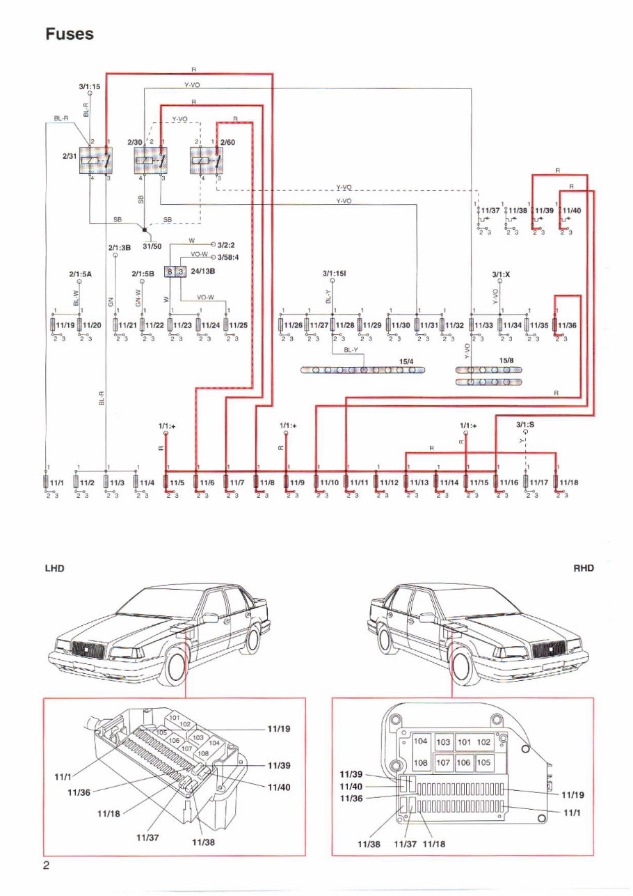
Fuses
同
311:15 工业
却30【"
- yy。 --l
R
e
a
L_____
y.'{Q ------------ -- --- --
圭旦旦
μb 4T T3
几‘
a
'"钮 , 一一一一一
211 :3 8 31150
w
3/2 :2
2I l:5A 缸1 :151 ~1 二X
11130
'-- t... t...
23 23 23
R
>
d
BL-Y
1~'
I" "昼 ι ,筝 '"''''ιi
e
a
1门+ 111:+ 1/1:+ 311 :8
o
>'
,
?LrM
IL-
bh
区
"
z
11。
忑.
"
J t :但
111 ‘
,
m
3
'
im km
1 1/10
3
R
11 11 1
3
11115
3
-AUh
3
LHD RHD
11 /36
1 1/19
1111
11119
11 139
1111"' '' \ 3沁户吃~"练习萨伞ι//1 1 11 /39
11/40 I 11/40
11137
刊 138
刊 138 11 /37 11118
2
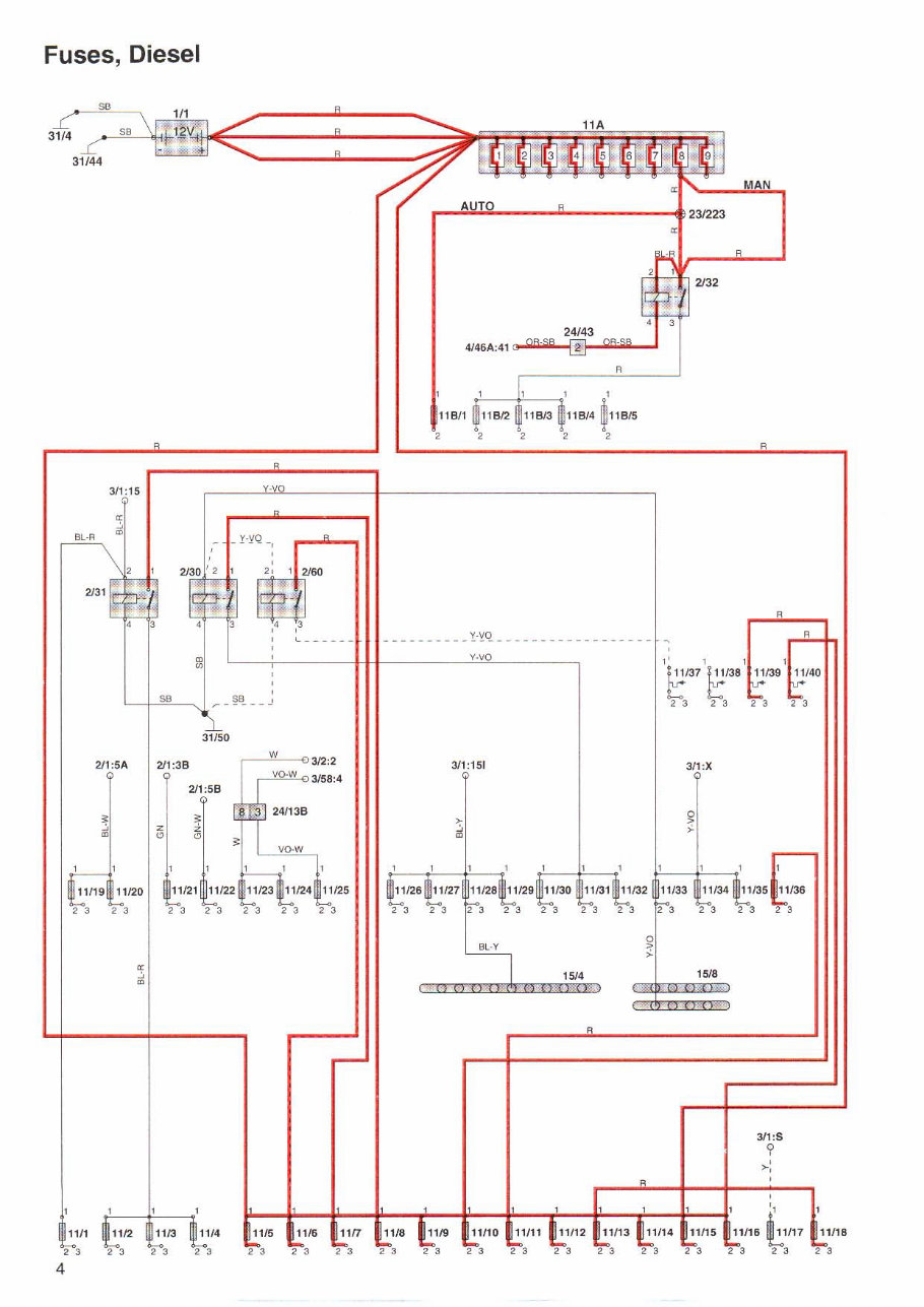
Fuses , Diesel
问
24f43
帆6Ä:41 3 (j R-öß [! •
., ,
同
"时
, , 2
且
12 11
羊OY!:. 311 : 15 ZI」B
R m
8
L 千 一一 - u 1---------- ,'"-
主旦旦
γ7 t;:ßØ ~ 二
问了'3 4T T3
四"
31150
、v
3/2 :2
311 :1驯 311 :X 211 :5A I 211 :38
2323232323
,如
d
2
,如
211:58
军
副
•
Z|Z
-2 -3 -2 -3 -2 -312-3 -2 -3
2
>
a
l
d
1~4
1町回
J主
"Æ 由 1116 1111厅 111118 圃 ,,~ 四 1111。 回 11111
311:8
?
>,
.
言-, T ,
4 :川5 1::ne L rh
11/1
23 23 23 23
2 3 23 2 3 2 3 2-3 2 -3 -2 -3 -2-3
4
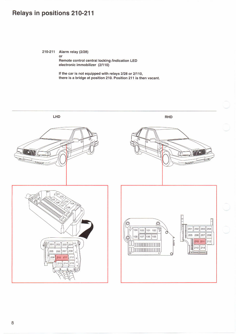
Relays in positions 210-211
8
210-211 Alarm relay (2128)
。r
Remote control central locking lindication LED
electronic immobilizer (2月 10)
If the car is not equipped with relays 2/28 or 21110 ,
there is a bridge at position 210. Position 211 is then vacant.
LHD RHD
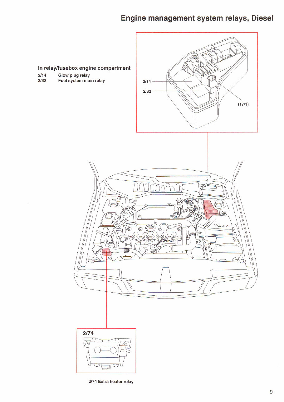
Engine management system relays , Diesel
In relay/fusebox engine compartment
2/14
2/32
Glow plug relay
Fuel system main relay
却74
2厅4 Extra heater relay
2114
2132
9
百
211:1A
制6A:揭
4145A:10
4月 OA:l0
4哑 8A;10
Y
一一一一一一- - --一一一 一~ - --一一一 - -→ J一 l
413:3T
~l,!lO.. :;:;
vn 斗A
m
GN-R
纪J且三能豆t!.!j
AUTO
Y-\/O
""
Y-VO
回 I 312:2
"
241138 "刷
511A:18 血?3
1
(
'
1
2 犁,-主--zo--尼明?--h@bLU
211:5A
o
F
1日4
~137 t ß8
,.,
伫7
1116
81屿 1 EZ129K 队啊
u 一一←一一一 ...._-- ...,
4115:3
。 哩"坦尊 !llo 哩
u‘ ~:3 MOTRON IC 4_314_4 BL.R
。 }.iQT.R9_N1C_4.可",!.,! !Il..~
FENIX 5.2
飞
乱, EOZ32ZH曲-u-帽UZFFUω-u
F
俨
3 1/4
ZE 。7@F、,白宫、.
E dp俨F丽
~ fl l:f! -Ð 4128A:30 ' I
mmm
24143
11B13
,
~旦,.,
c平!
画:
ττγ兰
2
主
23/<l
四1 且ι…ERZR丰
、,
"""
2
2主
基
高
"即1
恒
R
4128A:10
~铺A,刊
4146A :29 0-
4 山6A:43
的1:5
24154:3
n
4146A: 41
制冈
同
l i ;工飞2 在自ZEffj窍S
R
主
"-'0 I 2131
" -omo-ORE。-H3aτ扭曲-3-muZHU曲-川剧
一一一一一一一一一一一一一 l一一一一一一一一一一一一一一一一一一一一 「 一
EJ L-Y
Y 叩
312:6
24113B
且且『王
R-SB
511A:16
312:7
队 V
Y 叩
3
"
,
I ‘
w
t
137
E刷
旦旦
24J2C
E
11 /32
419 :5
;n8 且 mk: 刷 1扣』川剧
24113B 爸
>
d
"刷 明?↓护H2
2z
d
2I1:5A 511A:18
"
'518
R
"
,~,
" "
, ,
"
24113C
r 一一一一一 -
l~lI17
"门6
3
11115
网"
3
11111
3
11110
3
1116
3
1115
3
"
队 R
1111
民 R
, ,
肌肉
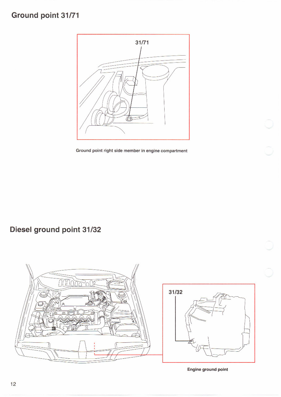
Ground point 31 斤 1
31 厅1
Ground point right side member in engine compartment
Diesel ground point 31/32
31/32
Engine ground point
12
You're Reading a Preview
What's Included?
Fast Download Speeds
Online & Offline Access
Access PDF Contents & Bookmarks
Full Search Facility
Print one or all pages of your manual
$30.99
Viewed 82 Times Today


Secure transaction
What's Included?
Fast Download Speeds
Online & Offline Access
Access PDF Contents & Bookmarks
Full Search Facility
Print one or all pages of your manual
$30.99
Discover the 1997 Volvo 850 Wiring Diagrams, a comprehensive set of diagrams to aid in understanding and troubleshooting the vehicle's electrical system. These detailed wiring diagrams visually represent the electrical connections and components within the 1997 Volvo 850, covering systems such as the engine, transmission, lighting, and audio.
Whether you're a professional technician or a Volvo 850 enthusiast, these wiring diagrams are invaluable for diagnosing electrical issues, locating specific components, and understanding the vehicle's wiring layout.
Compatible Models:
- 1997 Volvo 850 base sedan
- 1997 Volvo 850 GLT sedan
- 1997 Volvo 850 base wagon
- 1997 Volvo 850 GLT wagon
- 1997 Volvo 850 R sedan
- 1997 Volvo 850 R wagon
Acquire the 1997 Volvo 850 Wiring Diagrams today and gain the knowledge to effectively maintain and repair your Volvo 850's electrical system!


