Last Modified: 9-16-2014 6.6 F Doc ID: RM000000UZ20F9X Model Year: 2015 Model: Tundra Prod Date Range: [08/2014 - ] Title: INTRODUCTION: HOW TO TROUBLESHOOT ECU CONTROLLED SYSTEMS: GENERAL INFORMATION; 2015 MY Tundra [08/2014 - ] GENERAL INFORMATION A large number of ECU controlled systems are used in the TOYOTA TUNDRA. In general, ECU controlled systems are considered to be very intricate, requiring a high level of technical knowledge to troubleshoot. However, most problem checking procedures only involve inspecting the ECU controlled system's circuits one by one. An adequate understanding of the system and a basic knowledge of electricity is enough to perform effective troubleshooting, accurate diagnoses and necessary repairs. 1. TROUBLESHOOTING PROCEDURES The troubleshooting procedures consist of diagnosis procedures for when a DTC is stored and diagnosis procedures for when no DTC is stored. The basic idea is explained in the following table. PROCEDURE TYPE DETAILS TROUBLESHOOTING METHOD DTC Based Diagnosis The diagnosis procedure is based on the DTC that is stored. The malfunctioning part is identified based on the DTC detection conditions using a process of elimination. The possible trouble areas are eliminated one-by-one by use of the Techstream and inspection of related parts. Symptom Based Diagnosis (No DTCs stored) The diagnosis procedure is based on problem symptoms. The malfunctioning part is identified based on the problem symptoms using a process of elimination. The possible trouble areas are eliminated one-by-one by use of the Techstream and inspection of related parts. Vehicle systems are complex and use many ECUs that are difficult to inspect independently. Therefore, a process of elimination is used, where components that can be inspected individually are inspected, and if no problems are found in these components, the related ECU is identified as the problem and replaced. It is extremely important to ask the customer about the environment and the conditions present when the problem occurred (Customer Problem Analysis). This makes it possible to simulate the conditions and confirm the symptom. If the symptom cannot be confirmed or the DTC does not recur, the malfunctioning part may not be identified using the troubleshooting procedure, and the ECU for the related system may be replaced even though it is not defective. If this happens, the original problem will not be solved. In order to prevent endless expansion of troubleshooting procedures, the troubleshooting procedures are written with the assumption that multiple malfunctions do not occur simultaneously for a single problem symptom. To identify the malfunctioning part, troubleshooting procedures narrow down the target by separating components, ECUs and wire harnesses during the inspection. If the wire harness is identified as the cause of the problem, it is necessary to inspect not only the connections to components and ECUs but also all of the wire harness connectors between the component and the ECU. DIAGNOSTIC TESTER INTRODUCTION: HOW TO TROUBLESHOOT ECU CONTROLLE... https://techinfo.toyota.com/t3Portal/document/rm/RM26B0U/xhtml/RM... 1 of 3 2/18/2015 11:11 AM
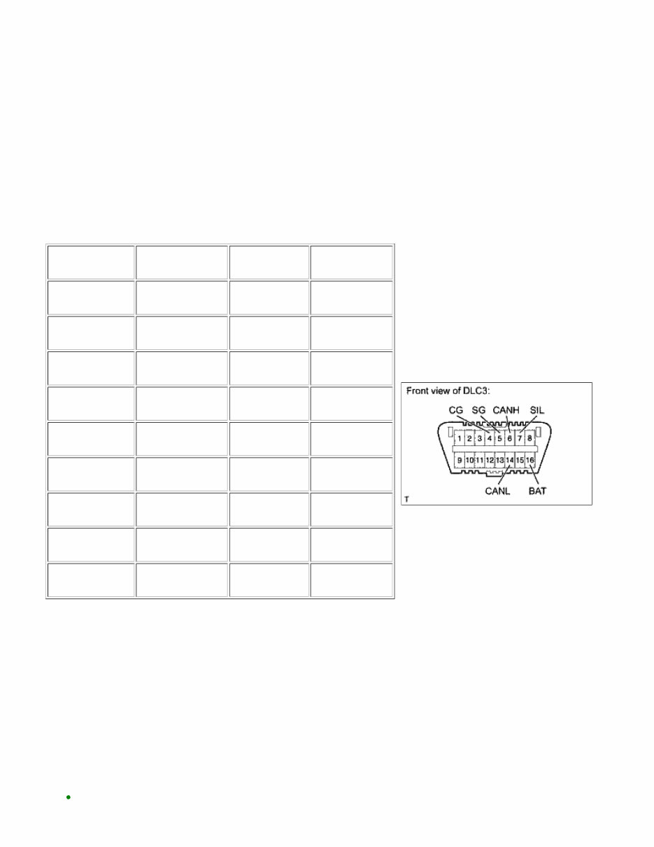
2. DESCRIPTION System data and the Diagnostic Trouble Codes (DTCs) can be read from the Data Link Connector 3 (DLC3) of the vehicle. When the system seems to be malfunctioning, use the Techstream* to check for a malfunction and perform repairs. HINT: *: Techstream is the name for the diagnostic tester in North America. 3. DATA LINK CONNECTOR 3 (DLC3) (a) The vehicle's ECU uses the ISO 15765-4 communication protocol. The terminal arrangement of the DLC3 complies with SAE J1962 and matches the ISO 15765-4 format. TERMINAL NO. (SYMBOLS) TERMINAL DESCRIPTION CONDITION SPECIFIED CONDITION 7 (SIL) - 5 (SG) Bus "+" line During transmission Pulse generation 4 (CG) - Body ground Chassis ground Always Below 1 Ω 5 (SG) - Body ground Signal ground Always Below 1 Ω 16 (BAT) - Body ground Battery positive Always 11 to 14 V 6 (CANH) - 14 (CANL) CAN bus line Ignition switch OFF* 54 to 69 Ω 6 (CANH) - 4 (CG) HIGH-level CAN bus line Ignition switch OFF* 200 Ω or higher 14 (CANL) - 4 (CG) LOW-level CAN bus line Ignition switch OFF* 200 Ω or higher 6 (CANH) - 16 (BAT) HIGH-level CAN bus line Ignition switch OFF* 6 kΩ or higher 14 (CANL) - 16 (BAT) LOW-level CAN bus line Ignition switch OFF* 6 kΩ or higher NOTICE: *: Before measuring the resistance, leave the vehicle as is for at least 1 minute and do not operate the ignition switch, any other switches, or the doors. If the result is not as specified, the DLC3 may have a malfunction. Repair or replace the harness and connector. (b) Connect the cable of the Techstream to the DLC3, turn the ignition switch ON and attempt to use the tester. If the display indicates that a communication error has occurred, there is a problem either with the vehicle or with the tester. HINT: If communication is normal when the tester is connected to another vehicle, inspect the DLC3 of the INTRODUCTION: HOW TO TROUBLESHOOT ECU CONTROLLE... https://techinfo.toyota.com/t3Portal/document/rm/RM26B0U/xhtml/RM... 2 of 3 2/18/2015 11:11 AM
original vehicle. If communication is still not possible when the tester is connected to another vehicle, the problem may be in the tester itself. Consult the Service Department listed in the tester's instruction manual. INTRODUCTION: HOW TO TROUBLESHOOT ECU CONTROLLE... https://techinfo.toyota.com/t3Portal/document/rm/RM26B0U/xhtml/RM... 3 of 3 2/18/2015 11:11 AM
NEXT NEXT NEXT Last Modified: 9-16-2014 6.6 F Doc ID: RM000002V5U01FX Model Year: 2015 Model: Tundra Prod Date Range: [08/2014 - ] Title: INTRODUCTION: HOW TO TROUBLESHOOT ECU CONTROLLED SYSTEMS: HOW TO PROCEED WITH TROUBLESHOOTING; 2015 MY Tundra [08/2014 - ] HOW TO PROCEED WITH TROUBLESHOOTING 1. OPERATION FLOW HINT: Perform troubleshooting in accordance with the procedures below. The following is an outline of basic troubleshooting procedures. Confirm the troubleshooting procedures for the circuit you are working on before beginning troubleshooting. 1. VEHICLE BROUGHT TO WORKSHOP 2. CUSTOMER PROBLEM ANALYSIS (a) Ask the customer about the conditions and environment when the problem occurred. 3. INSPECT BATTERY VOLTAGE Standard voltage: 11 to 14 V If the voltage is below 11 V, recharge or replace the battery before proceeding. 4. SYMPTOM CONFIRMATION AND DTC (INCLUDING FREEZE FRAME DATA) CHECK (a) Visually check the wire harnesses, connectors and fuses for open and short circuits. (b) Warm up the engine to the normal operating temperature. INTRODUCTION: HOW TO TROUBLESHOOT ECU CONTROLLE... https://techinfo.toyota.com/t3Portal/document/rm/RM26B0U/xhtml/RM... 1 of 10 2/18/2015 11:11 AM
A NEXT NEXT (c) Confirm the problem symptoms and conditions, and check for DTCs. Result RESULT PROCEED TO DTC is output A DTC is not output B B Go to step 6 5. DTC CHART (a) Check the results obtained in the DTC check. Then find the output DTC in the DTC chart. Look at the "Trouble Area" column for a list of potentially malfunctioning circuits and / or parts. NEXT Go to step 7 6. PROBLEM SYMPTOMS TABLE (a) Check the results obtained in the symptom confirmation. Then find the problem symptoms in the problem symptoms table. Look at the "Suspected Area" column for a list of potentially malfunctioning circuits and / or parts. 7. CIRCUIT INSPECTION OR PARTS INSPECTION (a) Confirm the malfunctioning circuit or part. 8. ADJUST, REPAIR OR REPLACE INTRODUCTION: HOW TO TROUBLESHOOT ECU CONTROLLE... https://techinfo.toyota.com/t3Portal/document/rm/RM26B0U/xhtml/RM... 2 of 10 2/18/2015 11:11 AM
You're Reading a Preview
What's Included?
Lifetime Access
Fast Download Speeds
Online & Offline Access
Access PDF Contents & Bookmarks
Full Search Facility
Print one or all pages of your manual
$34.99
2015-2020 Toyota Tundra OEM Service & Repair Manual
The 2015-2020 Toyota Tundra OEM Service & Repair Manual is a comprehensive guide designed to assist in the maintenance, repair, and servicing of Toyota Tundra models manufactured between 2015 and 2020.
This manual is an essential tool for Toyota Tundra owners, mechanics, and enthusiasts who want to ensure their vehicle is properly cared for. It provides detailed step-by-step instructions, diagrams, and illustrations to help you troubleshoot and fix various issues that may arise with your Tundra.
Whether you need to perform routine maintenance tasks like oil changes, brake inspections, or tire rotations, or tackle more complex repairs such as engine overhauls or electrical system troubleshooting, this manual has you covered. It covers all aspects of the vehicle, including the engine, transmission, suspension, electrical system, and more.
Key features of the 2015-2020 Toyota Tundra OEM Service & Repair Manual:
Comprehensive coverage of all major systems and components
Step-by-step instructions for maintenance, repair, and servicing
Detailed diagrams and illustrations to aid in the repair process
In-depth troubleshooting guides for common issues
Specifications and technical data for accurate repairs
Easy-to-follow format for users of all experience levels
Whether you are a DIY enthusiast or a professional mechanic, the 2015-2020 Toyota Tundra OEM Service & Repair Manual is an invaluable resource that will help you keep your Tundra running smoothly and efficiently. So, why wait? Get your copy now and take control of your Tundra's maintenance and repair needs.
Reviews
Q&A
Recently Viewed
5,521,897Happy Clients
2,594,462eManuals
1,120,453Trusted Sellers
15Years in Business
Price:
Actual Price:
2015-2020 Toyota Tundra OEM Service & Repair Manual