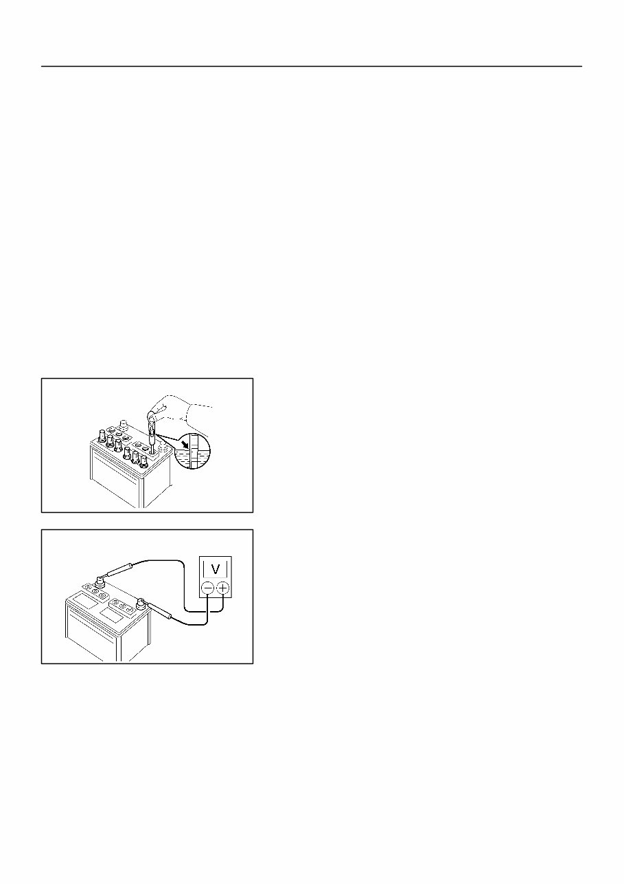
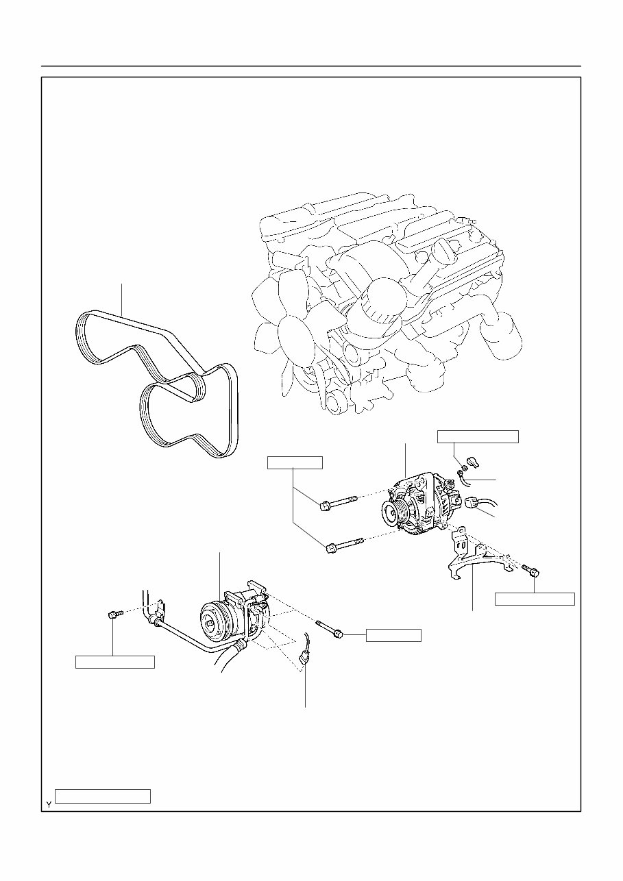
CH0N5-01 A01259 A01260 - CHARGING (1GR-FE) CHARGING SYSTEM CH-1 3825 Author: Date: CHARGING SYSTEM ON-VEHICLE INSPECTION CAUTION: z Check that the battery cables are connected to the correct terminals. z Disconnect the battery cables when the battery is giv- en a quick charge. z Do not perform tests with a high voltage insulation re- sistance tester. z Never disconnect the battery while the engine is run- ning. 1. CHECK BATTERY ELECTROLYTE LEVEL (a) Check the electrolyte quantity of each cell (Maintenance- Free Battery). If under the lower level, replace the battery (or add distilled wa- ter if possible) and check the charging system. (b) Check the electrolyte quantity of each cell (Except Main- tenance-Free Battery). If under the lower level, add distilled water. 2. CHECK BATTERY SPECIFIC GRAVITY (Except Maintenance-Free Battery) (a) Check the specific gravity of each cell. Standard specific gravity: 1.25 to 1.29 at 20_C (68_F) HINT: If the specific gravity is less than specification, charge the bat- tery. 3. CHECK BATTERY VOLTAGE (a) After having driven the vehicle and in the case that 20 minutes have not passed after having stopped the en- gine, turn the ignition switch ON and turn on the electrical system (headlight, blower motor, rear defogger etc.) for 60 seconds to remove the surface charge. (b) Turn the ignition switch OFF and turn off the electrical sys- tems. (c) Measure the battery voltage between the negative (-) and positive (+) terminals of the battery. Standard voltage: 12.5 to 12.9 V at 20_C (68_F) HINT: If the voltage is less than specification, charge the battery.
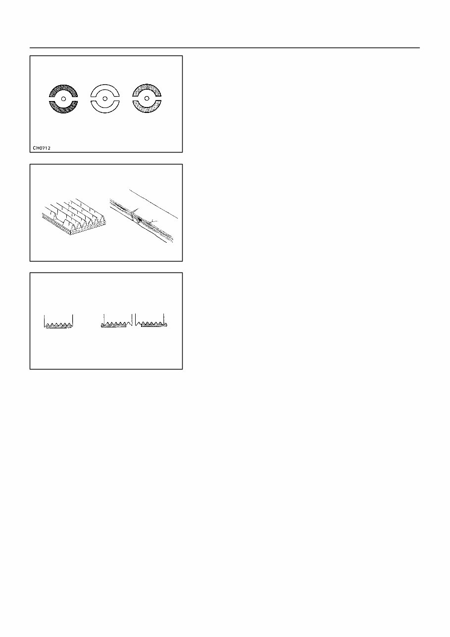
Z11580 B00543 B00540 CH-2 - CHARGING (1GR-FE) CHARGING SYSTEM 3826 Author: Date: (d) Check the indicator as shown in the illustration. HINT: z Blue: OK z White: Charging Necessary z Red: Insufficient Water 4. CHECK BATTERY TERMINALS, FUSIBLE LINK AND FUSES (a) Check that the battery terminals are not loose or cor- roded. (b) Check the fusible link, H-fuses and fuses for continuity. 5. INSPECT DRIVE BELT (a) Visually check the belt for excessive wear, frayed cords etc. HINT: z If any defect has been found, replace the drive belt. z Cracks on the rib side of a belt are considered acceptable. If the belt has chunks missing from the ribs, it should be replaced. (b) Check that it fits properly in the ribbed grooves. HINT: Check with your hand to confirm that the belt has not slipped out of the groove on the bottom of the pulley. 6. VISUALLY CHECK GENERATOR WIRING (a) Check that the wiring is in good condition. 7. LISTEN FOR ABNORMAL NOISES FROM GENERA- TOR (a) Check that there is no abnormal noise from the generator while the engine is running. 8. INSPECT CHARGE WARNING LIGHT CIRCUIT (a) Turn the ignition switch ON. Check that the charge warn- ing light comes on. (b) Start the engine. Check that the light goes off. HINT: If the light does not operate as specified, troubleshoot the charge warning light circuit. 9. INSPECT CHARGING CIRCUIT WITHOUT LOAD (a) If a battery/generator tester is available, connect the tes- ter to the charging circuit as per manufacturer’s instruc- tions.
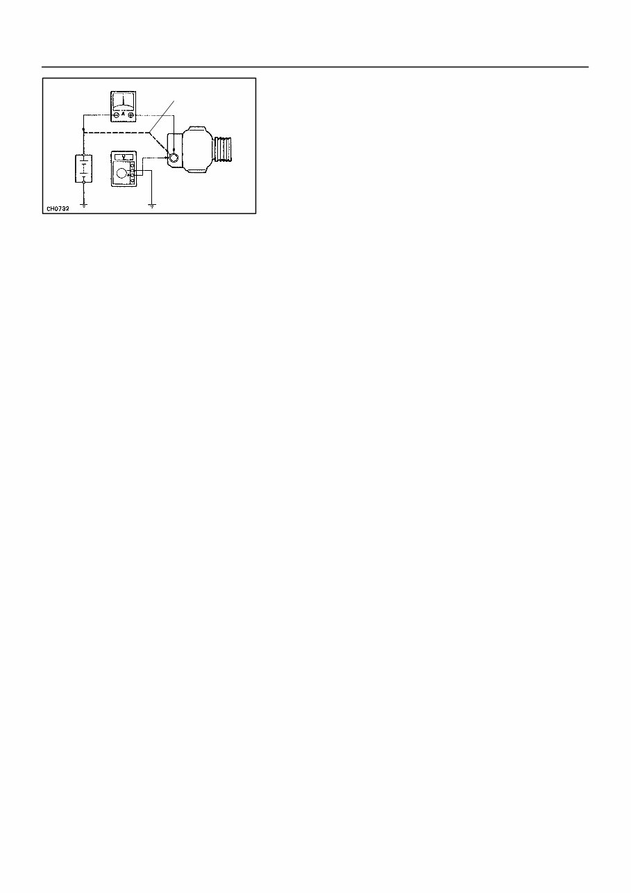
Z10324 Battery Ammeter Voltmeter Generator Disconnect Wire from Terminal B B - CHARGING (1GR-FE) CHARGING SYSTEM CH-3 3827 Author: Date: (b) If a tester is not available, connect a voltmeter to the charging circuit as follows. (1) Disconnect to the wire from terminal B of the gener- ator and connect it to the negative (-) lead of the ammeter. (2) Connect the positive (+) lead of the ammeter to ter- minal B of the generator. (3) Connect the positive (+) lead of the voltmeter to ter- minal B of the generator. (4) Ground the negative (-) lead of the voltmeter. (c) Check the charging circuit. (1) With the engine running from idle to 2,000 rpm, check the reading on the ammeter and voltmeter. Standard amperage: 10 A or less Standard voltage: 13.2 to 14.8 V HINT: z If the voltmeter reading is more than standard voltage, re- place the voltage regulator. z If the voltmeter reading is less than the standard voltage, check the voltage regulator and generator as follows: 10. INSPECT CHARGING CIRCUIT WITH LOAD (a) With the engine running at 2,000 rpm, turn on the high beam headlights and place the heater blower switch at ”HI”. (b) Check the reading on the ammeter. Standard amperage: 30 A or more HINT: z If the ammeter reading is less than standard amperage, repair the generator. z If the battery is fully charged, the indication will sometimes be less than standard amperage.
Discover the 2002 Toyota Tundra Service & Repair Manual, an essential resource for maintaining and repairing your Toyota Tundra. This comprehensive manual is invaluable for professional mechanics and DIY enthusiasts alike.
Includes models such as:
2002 Toyota Tundra SR5
2002 Toyota Tundra Limited
2002 Toyota Tundra SR5 V8
2002 Toyota Tundra Limited V8
Crafted specifically for the 2002 Toyota Tundra, this manual offers detailed, step-by-step instructions complemented by clear illustrations. Whether you're an experienced mechanic or a hands-on enthusiast, this manual equips you to handle any repair or maintenance task.
Highlighted features of the 2002 Toyota Tundra Service & Repair Manual:
Comprehensive information covering engine, transmission, suspension, electrical systems, and more
Troubleshooting guides for effective issue diagnosis and resolution
Maintenance schedules ensuring optimal performance and longevity
Exploded diagrams and detailed illustrations for easy comprehension
Instructions for both basic and advanced repairs and modifications
Empower yourself to address mechanical issues promptly. Acquire the 2002 Toyota Tundra Service & Repair Manual and take charge of your vehicle's maintenance requirements. Invest in this ultimate guide today and experience the assurance of keeping your Tundra in prime condition.