IN0I0-01 BO4111 Negative Cable IN-10 - INTRODUCTION FOR ALL OF VEHICLES 10 Author: Date: 2001 SIENNA (RM787U) FOR ALL OF VEHICLES PRECAUTION 1. FOR VEHICLES EQUIPPED WITH SRS AIRBAG AND SEAT BELT PRETENSIONER (a) The SIENNA is equipped with an SRS (Supplemental Re- straint System), such as the driver airbag, front passen- ger airbag assembly, side airbag assembly and seat belt pretensioner. Failure to carry out service operations in the correct se- quence could cause the supplemental restraint system to unexpectedly deploy during servicing, possibly leading to a serious accident. Further, if a mistake is made in servicing the supplemental restraint system, it is possible the SRS may fail to operate when required. Before servicing (including removal or installation of parts, inspection or replacement), be sure to read the following items carefully, then follow the cor- rect procedure described in this manual. (b) GENERAL NOTICE (1) Malfunction symptoms of the supplemental re- straint system are difficult to confirm, so the diag- nostic trouble codes become the most important source of information when troubleshooting. When troubleshooting the supplemental restraint system, always inspect the diagnostic trouble codes before disconnecting the battery (See page DI-358 ). (2) Work must be started after 90 seconds from the time the ignition switch is turned to the ”LOCK” posi- tion and the negative (-) terminal cable is discon- nected from the battery. (The supplemental restraint system is equipped with a back-up power source so that if work is started within 90 seconds of disconnecting the neg- ative (-) terminal cable from the battery, the SRS may deploy.) When the negative (-) terminal cable is discon- nected from the battery, memory of the clock and audio systems will be cancelled. So before starting work, make a record of the contents memorized by the each memory system. Then when work is fin- ished, reset the clock and audio systems as before. To avoid erasing the memory of each memory sys- tem, never use a back-up power supply from anoth- er battery.
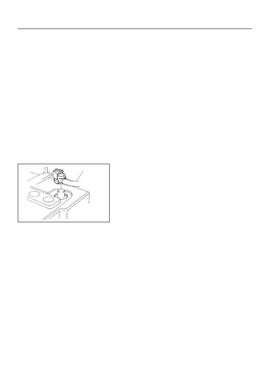
R11910 Red Mark - INTRODUCTION FOR ALL OF VEHICLES IN-1 1 11 Author: Date: 2001 SIENNA (RM787U) (3) Even in cases of a minor collision where the SRS does not deploy, the steering wheel pad, front pas- senger airbag assembly and seat belt pretensioner should be inspected (See page RS-14 , RS-28 , and BO-155 ). (4) Never use SRS parts from another vehicle. When replacing parts, replace them with new parts. (5) Before repairs, remove the airbag sensor if shocks are likely to be applied to the sensor during repairs. (6) Never disassemble and repair the airbag sensor as- sembly, steering wheel pad, front passenger airbag assembly or seat belt pretensioner. (7) If the airbag sensor assembly, steering wheel pad, front passenger airbag assembly or seat belt pre- tensioner have been dropped, or if there are cracks, dents or other defects in the case, bracket or con- nector, replace them with new ones. (8) Do not directly expose the airbag sensor assembly, steering wheel pad, front passenger airbag assem- bly or seat belt pretensioner to hot air or flames. (9) Use a volt/ohmmeter with high impedance (10 kΩ/V minimum) for troubleshooting of the electrical cir- cuit. (10) Information labels are attached to the periphery of the SRS components. Follow the instructions on the notices. (11) After work on the supplemental restraint system is completed, check the SRS warning light (See page DI-358 ). (c) SPIRAL CABLE (in Combination Switch) The steering wheel must be fitted correctly to the steering column with the spiral cable at the neutral position, other- wise cable disconnection and other troubles may result. Refer to SR-20 of this manual concerning correct steer- ing wheel installation.
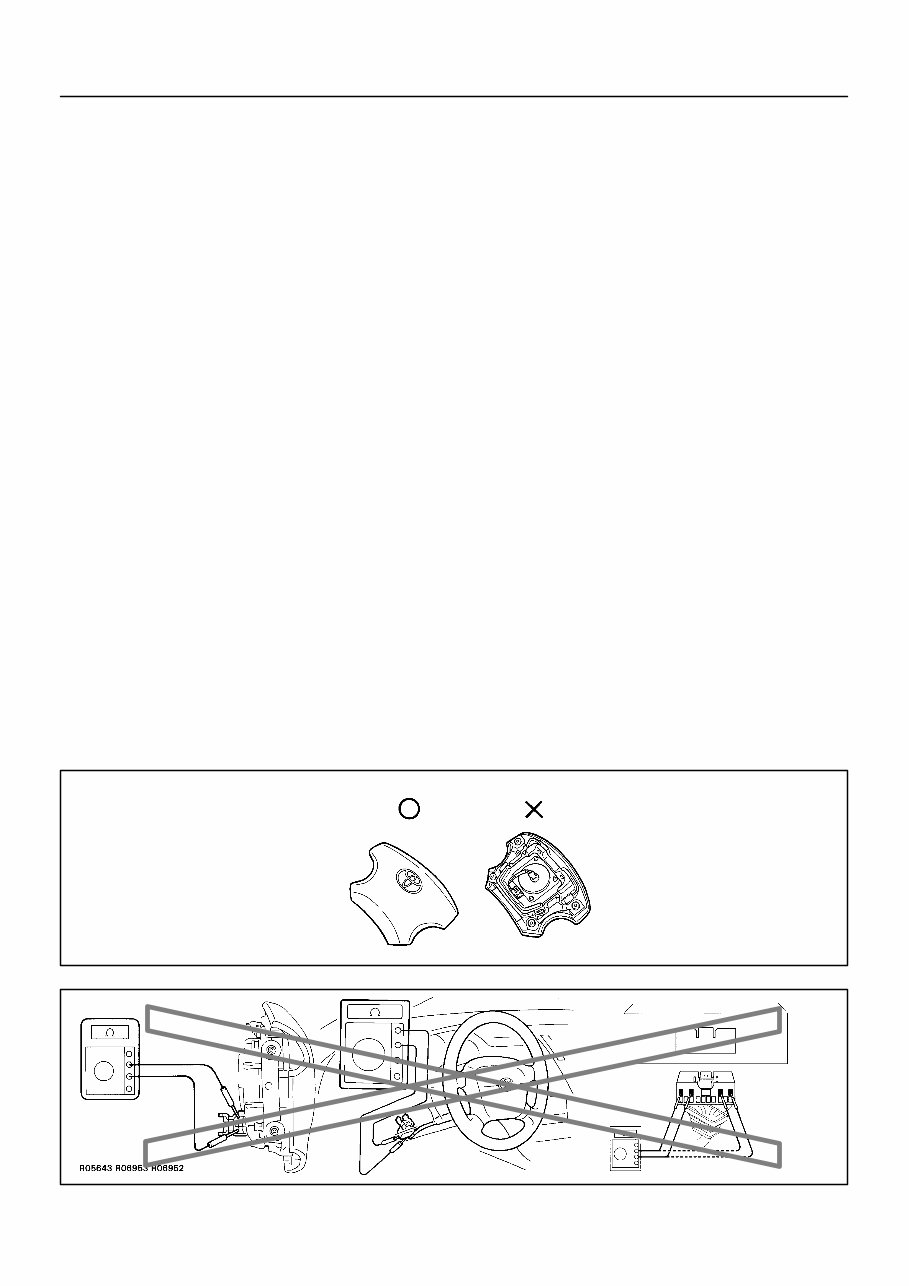
B09710 Example: Correct Wrong Z13950 Example: IN-12 - INTRODUCTION FOR ALL OF VEHICLES 12 Author: Date: 2001 SIENNA (RM787U) (d) STEERING WHEEL PAD (with Airbag) (1) When removing the steering wheel pad or handling a new steering wheel pad, it should be placed with the pad top surface facing up. In this case, care should be taken to place it so the connector will not be damaged. In addition do not store a steering wheel pad on top of another one. Storing the pad with its metallic surface up may lead to a serious accident if the airbag inflates for some reason. (2) Never measure the resistance of the airbag squib. (This may cause the airbag to deploy, which is very dangerous.) (3) Grease should not be attached to the steering wheel pad and the pad should not be cleaned with detergents of any kind. (4) Store the steering wheel pad where the ambient temperature remains below 93°C (200°F), without high humidity and away from electrical noise. (5) When using electric welding, first disconnect the air- bag connector (yellow color and 2 pins) under the steering column near the combination switch con- nector before starting work. (6) When disposing of a vehicle or the steering wheel pad alone, the airbag should be deployed using an SST before disposal (See page RS-16 ). Carry out the operation in a safe place away from electrical noise.
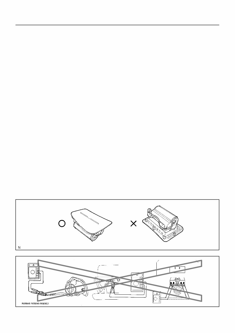
B02919 Example: Correct Wrong Z13951 Example: - INTRODUCTION FOR ALL OF VEHICLES IN-13 13 Author: Date: 2001 SIENNA (RM787U) (e) FRONT PASSENGER AIRBAG ASSEMBLY (1) Always store a removed or new front passenger air- bag assembly with the airbag deployment direction facing up. Storing the airbag assembly with the airbag deploy- ment direction facing down could cause a serious accident if the airbag inflates. (2) Never measure the resistance of the airbag squib. (This may cause the airbag to deploy, which is very dangerous.) (3) Grease should not be applied to the front passen- ger airbag assembly and the airbag door should not be cleaned with detergents of any kind. (4) Store the airbag assembly where the ambient tem- perature remains below 93°C (200°F), without high humidity and away from electrical noise. (5) When using electric welding, first disconnect the air- bag connector (yellow color and 2 pins) installed on the assembly before starting work. (6) When disposing of a vehicle or the airbag assembly alone, the airbag should be deployed using an SST before disposal (See page RS-30 ). Perform the operation in a safe place away from electrical noise.
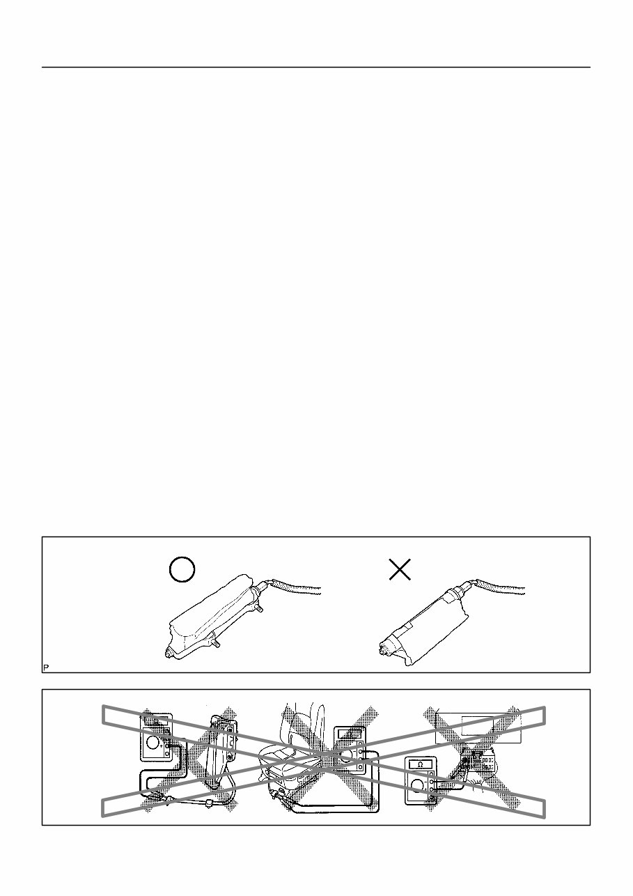
B02922 Example: Correct Wrong N21642 Example: IN-14 - INTRODUCTION FOR ALL OF VEHICLES 14 Author: Date: 2001 SIENNA (RM787U) (f) SIDE AIRBAG ASSEMBLY (1) Always store a removed or new side airbag assem- bly with the airbag deployment direction facing up. Storing the airbag assembly with the airbag deploy- ment direction facing down could cause a serious accident if the airbag deploys. (2) Never measure the resistance of the airbag squib. (This may cause the airbag to deploy, which is very dangerous.) (3) Grease should not be applied to the side airbag as- sembly and the surface should not be cleaned with detergents of any kind. (4) Store the airbag assembly where the ambient tem- perature remains below 93°C (200°F), without high humidity and away from electrical noise. (5) When using electric welding, first disconnect the air- bag connector (yellow color and 2 pins) under the seat before starting work. (6) When disposing of a vehicle or the side airbag as- sembly alone, the airbag should be deployed using an SST before disposal (See page RS-42 ). Perform the operation in a safe place away from electrical noise.
Whether you're a professional mechanic or a DIY enthusiast, this repair manual enables you to address vehicle issues using a comprehensive approach. It encompasses troubleshooting and replacement procedures recommended by the manufacturer, complete with step-by-step instructions, clear images, and exploded-view illustrations.
While the durability of your vehicle is undeniable, regular maintenance is essential. Over time, certain parts will wear out and require replacement.
Fortunately, a reliable repair manual is invaluable, offering the manufacturer's recommended troubleshooting charts and replacement procedures. This resource empowers you to handle vehicle repairs, ultimately saving on costs, enhancing vehicle reliability, and reducing reliance on repair shops.
The manual includes detailed troubleshooting and replacement procedures, step-by-step instructions, exploded-view illustrations, and clear images.
With this manual, there's no need to sift through numerous pages to locate specific information, eliminating the hassle of dealing with greasy, torn, or lost pages. It's easily accessible, searchable, and can be bookmarked, offering a more convenient alternative to traditional bound manuals.
Additionally, if you prefer a physical copy, you have the option to print it out.
Printable: Yes Language: English Compatibility: Compatible with various electronic devices, including PC & Mac computers, Android and Apple smartphones & tablets, etc. Requirements: Adobe Reader (free)