

2003-2005 Suzuki Ignis Service & Repair Manual
What's Included?
Fast Download Speeds
Offline Viewing
Access Contents & Bookmarks
Full Search Facility
Print one or all pages of your manual

IMPORTANT
WARNING/CAUTION/NOTE
Please read this manual and follow its instructions carefully. To emphasize special information, the words
WARNING, CAUTION and NOTE have special meanings. Pay special attention to the messages highlighted by
these signal words.
WARNING:
Indicates a potential hazard that could result in death or injury.
CAUTION:
Indicates a potential hazard that could result in vehicle damage.
NOTE:
Indicates special information to make maintenance easier or instructions clearer.
WARNING:
This service manual is intended for authorized Suzuki dealers and qualified service mechanics only.
Inexperienced mechanics or mechanics without the proper tools and equipment may not be able to
properly perform the services described in this manual.
Improper repair may result in injury to the mechanic and may render the vehicle unsafe for the driver
and passengers.
WARNING:
For vehicles equipped with a Supplemental Restraint (Air Bag) System:
• Service on and around the air bag system components or wiring must be performed only by an
authorized SUZUKI dealer. Refer to “Air Bag System Components and Wiring Location View” under
“General Description” in air bag system section in order to confirm whether you are performing ser-
vice on or near the air bag system components or wiring. Please observe all WARNINGS and “Ser-
vice Precautions” under “On-Vehicle Service” in air bag system section before performing service
on or around the air bag system components or wiring. Failure to follow WARNINGS could result in
unintentional activation of the system or could render the system inoperative. Either of these two
conditions may result in severe injury.
• If the air bag system and another vehicle system both need repair, Suzuki recommends that the air
bag system be repaired first, to help avoid unintended air bag system activation.
• Do not modify the steering wheel, instrument panel or any other air bag system component (on or
around air bag system components or wiring). Modifications can adversely affect air bag system
performance and lead to injury.
• If the vehicle will be exposed to temperatures over 93°C (200°F) (for example, during a paint baking
process), remove the air bag system components (air bag (inflator) modules, SDM and/or seat belt
with pretensioner) beforehand to avoid component damage or unintended activation.
FOREWORD
This manual contains procedures for diagnosis, maintenance, adjustments, minor service operations, replace-
ment of components (Service) and for disassembly and assembly of major components (Unit Repair-Overhaul).
Applicable model: RG413
The contents are classified into sections each of which is given a section number as indicated in the Table of
Contents on following page. And on the first page of each individual section is an index of that section.
This manual should be kept in a handy place for ready reference of the service work.
Strict observance of the so specified items will enable one to obtain the full performance of the vehicle.
When replacing parts or servicing by disassembling, it is recommended to use SUZUKI genuine parts, tools and
service materials (lubricant, sealants, etc.) as specified in each description.
All information, illustrations and specifications contained in this literature are based on the latest product infor-
mation available at the time of publication approval. And used as the main subject of description is the vehicle of
standard specifications among others.
Therefore, note that illustrations may differ from the vehicle being actually serviced.
The right is reserved to make changes at any time without notice.
Related Manual
© COPYRIGHT SUZUKI MOTOR CORPORATION 2000
Manual Name Manual No.
RG413 Wiring Diagram Manual 99512-80G00-015
TABLE OF CONTENTS
GENERAL INFORMATION ENGINE 0A 6
General Information 0A General Information and Diagnosis 6 0B 6A1
Maintenance and Lubrication 0B Engine Mechanical 6A1 6B
HEATING AND AIR CONDITIONING Engine Cooling 6B 1A 6C
Heater and Ventilation 1A Engine Fuel 6C 1B 6E1
Air Conditioning 1B Engine and Emission Control System 6E1 6F1
STEERING, SUSPENSION, WHEELS
AND TIRES
Ignition System 6F1 3 6G
Cranking System 6G 3A 6H
Steering, Suspension, Wheels and Tires 3 Charging System 6H 3B 6K
Front End Alignment 3A Exhaust System 6K 3B1 6B
Manual Rack and Pinion 3B TRANSMISSION, CLUTCH AND
DIFFERENTIAL
3C 7A
Power Steering System 3B1 3D 7B
Steering Wheel and Column 3C Manual Transmission 7A 3E 7C
Front Suspension 3D Automatic Transmission 7B 3F 7D
Rear Suspension 3E Clutch 7C 7F
Wheels and Tires 3F Transfer 7D 4A
DRIVE SHAFT AND PROPELLER SHAFT Differential (Rear)(4WD) 7F 4B 8
Front Drive Shaft 4A ELECTRICAL SYSTEM 8A
Propeller Shaft 4B Body Electrical System 8 5 8G
BRAKE SYSTEM Wiring Diagram 8A 5E
Brakes 5 Immobilizer Control System (if equipped) 8G 9
Antilock Brake System 5E BODY SERVICE 9
RESTRAINT SYSTEM 10
Restraint System 10 10B
Air Bag System (if equipped) 10B
NOTE:
The screen toned Section 8A is in Wiring Diagram Manual mentioned in FOREWORD of this manual.

GENERAL INFORMATION 0A-1
0A
6F2
6G
6H
6K
7A
7A1
7B1
7C1
7D
7E
7F
8A
8B
8C
8D
8E
9
10
10A
10B
SECTION 0A
GENERAL INFORMATION
CONTENTS
HOW TO USE THIS MANUAL .........................0A-2
PRECAUTIONS ................................................ 0A-3
PRECAUTION FOR VEHICLES EQUIPPED
WITH A SUPPLEMENTAL RESTRAINT
(AIR BAG) SYSTEM ..................................... 0A-3
DIAGNOSIS .............................................. 0A-3
SERVICING AND HANDLING .................. 0A-4
GENERAL PRECAUTIONS .......................... 0A-6
PRECAUTIONS FOR CATALYTIC
CONVERTER................................................ 0A-9
PRECAUTION FOR INSTALLING MOBILE
COMMUNICATION EQUIPMENT ................. 0A-9
PRECAUTION IN SERVICING FULL-TIME
4WD VEHICLE ............................................ 0A-10
PRECAUTIONS FOR ELECTRICAL
CIRCUIT SERVICE ..................................... 0A-11
ELECTRICAL CIRCUIT INSPECTION
PROCEDURE ............................................. 0A-13
OPEN CIRCUIT CHECK ......................... 0A-13
CONTINUITY CHECK ............................. 0A-14
VOLTAGE CHECK .................................. 0A-15
SHORT CIRCUIT CHECK (WIRE
HARNESS TO GROUND)....................... 0A-16
INTERMITTENT AND POOR
CONNECTION ............................................ 0A-16
IDENTIFICATION INFORMATION ................. 0A-18
VEHICLE IDENTIFICATION NUMBER ...... 0A-18
ENGINE IDENTIFICATION NUMBER ........ 0A-18
TRANSMISSION IDENTIFICATION
NUMBER .................................................... 0A-18
WARNING, CAUTION AND INFORMATION
LABELS.......................................................... 0A-19
VEHICLE LIFTING POINTS ........................... 0A-20
ABBREVIATIONS AND SYMBOLS MAY
BE USED IN THIS MANUAL.......................... 0A-22
FASTENER INFORMATION .......................... 0A-25
METRIC FASTENERS................................ 0A-25
FASTENER STRENGTH
IDENTIFICATION ....................................... 0A-25
STANDARD TIGHTENING TORQUE......... 0A-25
0A-2 GENERAL INFORMATION
HOW TO USE THIS MANUAL
1) There is a “TABLE OF CONTENTS” on the third page of this manual, whereby you can easily find the sec-
tion that offers the information you need. Also, there is a CONTENTS on the first page of each section,
where the main items in that section are listed.
2) Each section of this manual has its own pagination. It is indicated at the top of each page along with the Sec-
tion name.
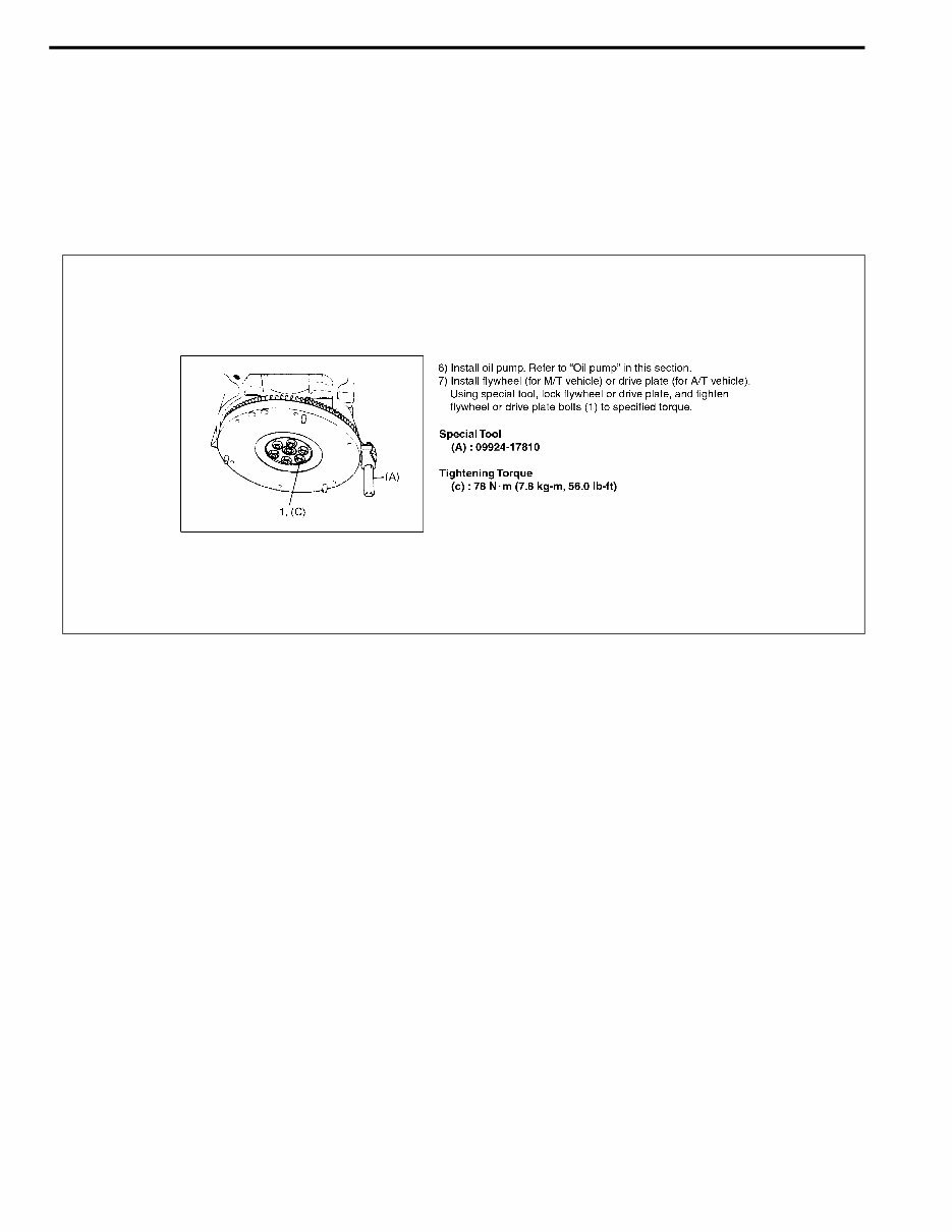
3) The special tool usage and torque specification are given as shown in the figure.
4) A number of abbreviations and symbols are used in the text.For their full explanations, refer to “ABBREVIA-
TIONS AND SYMBOLS MAY BE USED IN THIS MANUAL” in this section.
5) The SI, metric and foot-pound systems are used as units in this manual.
6) “DIAGNOSIS” are included in each section as necessary.
7) At the end of each section, there are descriptions of “SPECIAL TOOL”, “REQUIRED SERVICE MATERIAL”
and “TIGHTENING TORQUE SPECIFICATION” that should be used for the servicing work described in that
section.
You're Reading a Preview
What's Included?
Fast Download Speeds
Offline Viewing
Access Contents & Bookmarks
Full Search Facility
Print one or all pages of your manual
$31.99
$41.99
Viewed 58 Times Today


Secure transaction
What's Included?
Fast Download Speeds
Offline Viewing
Access Contents & Bookmarks
Full Search Facility
Print one or all pages of your manual
$31.99
$41.99
Get instant access to the Complete Factory Service Repair Workshop Manual without any extra fees or expiry dates. This Professional Manual is suitable for both professional Mechanics and Technicians, as well as DIY enthusiasts. It covers all repairs, servicing, and troubleshooting procedures with detailed photos, diagrams, step-by-step instructions, and highly detailed exploded diagrams & pictures to ensure every job is completed correctly.
Print out a single page or the entire manual as per your choice. This Manual can be used on multiple computers without any limitations or trial periods, and it does not expire or require any renewal fees. It is fully compatible with all Windows & MAC Computers.


