1998-2005 Suzuki Grand Vitara Service & Repair Manual
What's Included?
Lifetime Access
Fast Download Speeds
Offline Viewing
Access Contents & Bookmarks
Full Search Facility
Print one or all pages of your manual
Important WARNING/CAUTION/NOTE Please read this manual and follow its instructions carefully. To emphasize special information, the words WARNING, CAUTION and NOTE have special meanings. Pay special attention to the messages highlighted by these signal words. The circle with a slash in this manual means “Don’t do this” or “Don’t let this happen”. WARNING: Indicates a potential hazard that could result in death or injury. CAUTION: Indicates a potential hazard that could result in vehicle damage. NOTE: Indicates special information to make maintenance easier or instructions clearer. WARNING: This service manual is intended for authorized SUZUKI dealers and qualified service mechanics only. Inexperienced mechanics or mechanics without the proper tools and equipment may not be able to properly perform the services described in this manual. Improper repair may result in injury to the mechanic and may render the vehicle unsafe for the driver and passengers. WARNING: For vehicles equipped with a Supplemental Restraint (Air Bag) System : • Service on and around the air bag system components or wiring must be performed only by an authorized SUZUKI dealer. Refer to “Air Bag System Components and Wiring Location View” under “General Description” in air bag system section in order to confirm whether you are performing service on or near the air bag system components or wiring. Please observe all WARNINGS and “Service Precautions” under “On-Vehicle Service” in air bag system section before performing service on or around the air bag system components or wiring. Failure to follow WARNINGS could result in unintentional activation of the system or could render the system inoperative. Either of these two conditions may result in severe injury. • If the air bag system and another vehicle system both need repair, SUZUKI recommends that the air bag system be repaired first, to help avoid unintended air bag system activation. • Do not modify the steering wheel, instrument panel or any other air bag system component (on or around air bag system components or wiring). Modifications can adversely affect air bag system performance and lead to injury. • If the vehicle will be exposed to temperatures over 93°C (200°F) (for example, during a paint baking process), remove the air bag system components (air bag (inflator) module, sensing and diagnostic module (SDM), seat belt pretensioner (if equipped) beforehand to avoid component damage or unin- tended activation.
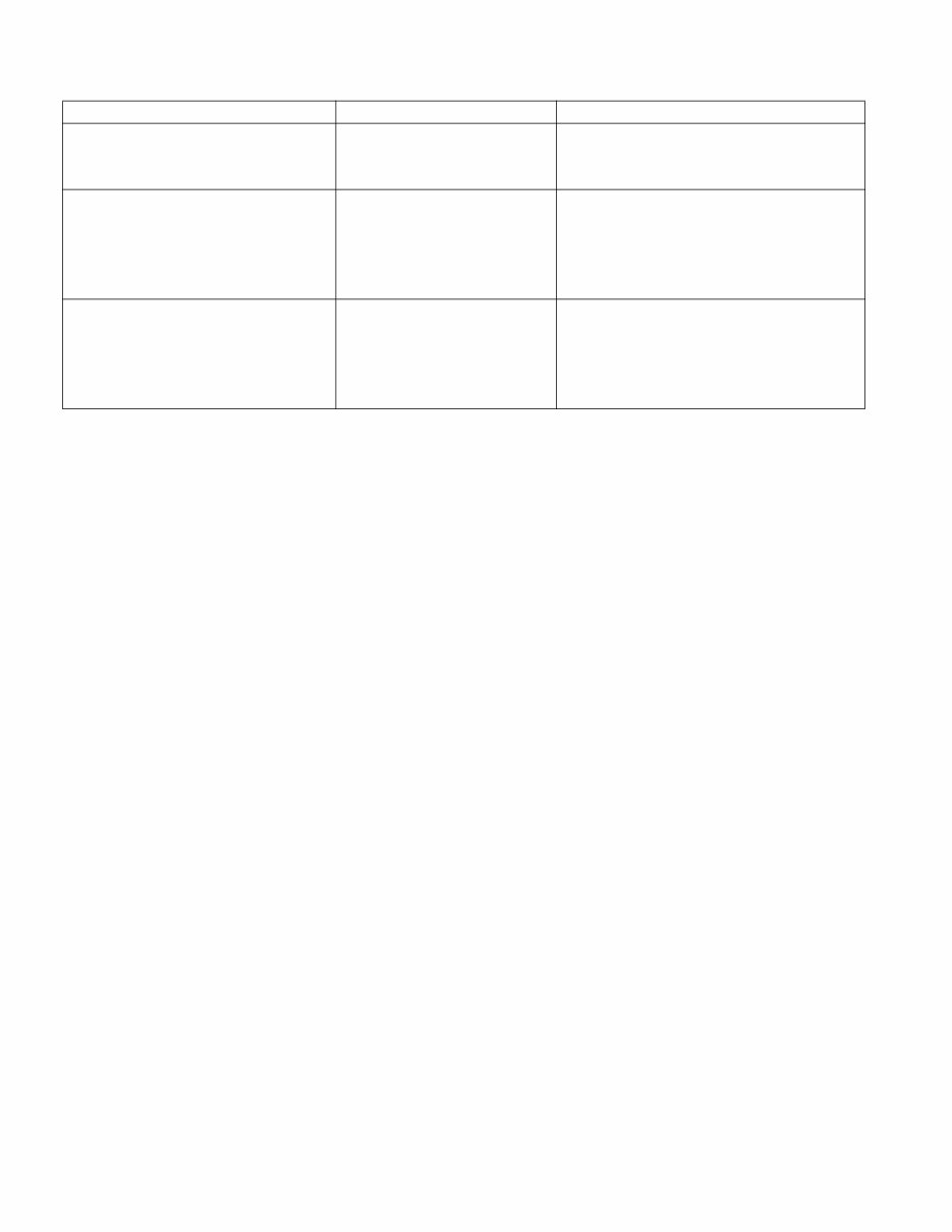
RELATED MANUAL : MANUAL NAME MANUAL NO. APPLICABILITY GRAND VITARA/GRAND VITARA XL-7 (SQ416/SQ420/SQ625/JA627) Unit Repair Manual 99501-65D40-01E Transmission, Transfer and Differentials (Front and Rear) of applicable model mentioned in “Foreword” of this manual. GRAND VITARA/GRAND VITARA XL-7 (SQ416/SQ420/SQ625/JA627) Wiring Diagram Manual 99512-52D10-015 Applicable model mentioned in “Fore- word” of this manual. Other than vehicle identification number of 2S2GTA03C00###### and 2S2GTA52C00######. SQ416/SQ420/SQ625 Wiring Dia- gram Manual 99512-65D11-015 Applicable model mentioned in “Fore- word” of this manual. Vehicle identification number of 2S2GTA03C00###### and 2S2GTA52C00######.
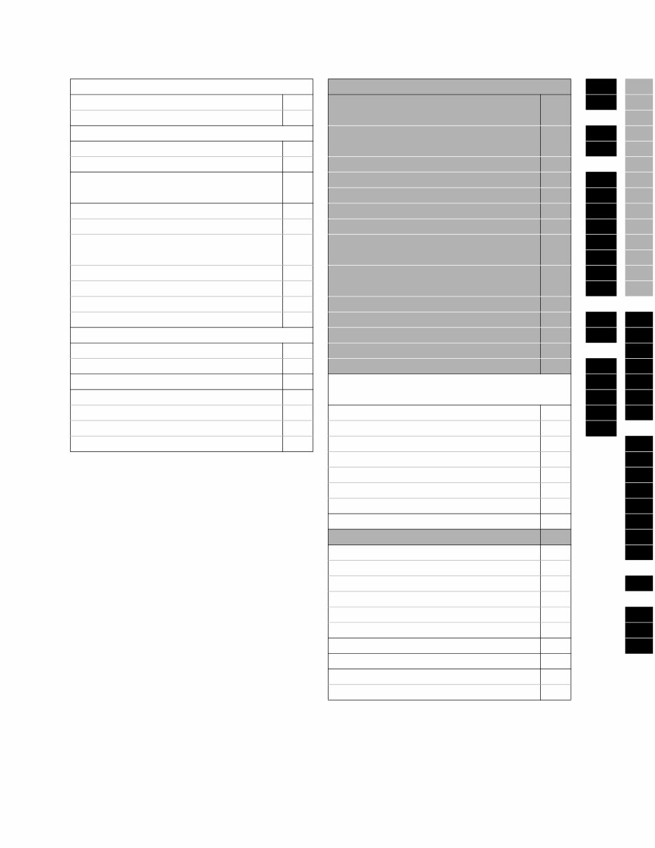
Table of Contents GENERAL INFORMATION ENGINE 0A 6 General Information 0A Engine General Information and Diagnosis (G16/J20) 6 0B 6-1 Maintenance and Lubrication 0B 6A1 HEATING AND AIR CONDITIONING Engine General Information and Diagnosis (H25) 6-1 1A 6A2 Heater and Ventilation 1A 1B 6A4 Air Conditioning 1B Engine Mechanical (G16) 6A1 6B STEERING, SUSPENSION, WHEELS AND TIRES 3 Engine Mechanical (H25) 6A2 3 6C Engine Mechanical (J20) 6A4 3A 6E1 Front End Alignment 3A Engine Cooling 6B 3B1 6E2 Power Steering (P/S) System 3B1 Engine Fuel 6C 3C 6F1 Steering Wheel and Column (Not Equipped with Air Bag) 3C Engine and Emission Control System (G16/J20) 6E1 3C1 6F2 3D 6G Air Bag Steering Wheel and Column 3C1 Engine and Emission Control System (H25) 6E2 3E 6H Front Suspension 3D 3F 6K Rear Suspension 3E Ignition System (G16) 6F1 Wheels and Tires 3F Ignition System (J20/H25) 6F2 4A2 7A DRIVE SHAFT/PROP. SHAFT Cranking System (Reduction Type) 6G 4B 7A1 Front Drive Shaft/Shaft Bearing, Oil Seal 4A2 Charging System 6H 7B1 Propeller Shafts 4B Exhaust System 6K 5 7C1 BRAKES 5 TRANSMISSION, CLUTCH AND DIFFERENTIAL 5A 7D Brakes Pipe/Hose/Master Cylinder 5A 5B 7E Front Brakes 5B Manual Transmission (Type 1) 7A 5C 7F Parking and Rear Brake 5C Manual Transmission (Type 2) 7A1 5E1 Antilock Brake System 5E1 Automatic Transmission 7B1 8 Clutch 7C1 8A Transfer 7D 8B Differential (Front) 7E 8C Differential (Rear) 7F 8D BODY ELECTRICAL SYSTEM 8 8E Wiring Diagram 8A 8G Lighting System 8B 8H Instrumentation/Driver Information 8C Windows, Mirrors, Security and Locks 8D 9 Cruise Control System 8E Immobilizer Control System 8G 10 Body Electrical Control Module 8H 10A BODY SERVICE 9 10B RESTRAINT SYSTEM 10 Seat Belt 10A Air Bag System 10B NOTE: The screen toned Sections 6 – 6K are included in Volume 2 and Section 8A is in Wiring Diagram Man- ual.
GENERAL INFORMATION 0A-1 0A SECTION 0A GENERAL INFORMATION CONTENTS How to Use This Manual .................................0A-2 Precautions......................................................0A-3 Precaution for Vehicles Equipped with a Supplemental Restraint (Air Bag) System..... 0A-3 Diagnosis................................................... 0A-3 Servicing and Handling ............................. 0A-4 General Precautions ..................................... 0A-7 Precautions for Catalytic Converter............... 0A-9 Precautions for Electrical Circuit Service .... 0A-10 Electrical Circuit Inspection Procedure........ 0A-11 Open circuit check ................................... 0A-11 Short circuit check (wire harness to ground) .................................................... 0A-13 Intermittent and Poor Connection ............... 0A-14 Precaution for Installing Mobile Communication Equipment ......................... 0A-15 Identification Information............................. 0A-16 Vehicle Identification Number ..................... 0A-16 Engine Identification Number ...................... 0A-16 Transmission Identification Number............ 0A-17 Warning, Caution and Information Labels............................................................. 0A-18 Vehicle Lifting Points ................................... 0A-19 Abbreviations May Be Used in This Manual............................................................ 0A-21 Metric Information......................................... 0A-24 Metric Fasteners ......................................... 0A-24 Fastener Strength Identification .................. 0A-24 Standard Tightening Torque........................ 0A-24
0A-2 GENERAL INFORMATION How to Use This Manual 1) There is a Table of Contents for The Whole Manual on the third page of this manual, whereby you can easily find the section that offers the information you need. Also, there is a Contents on the first page of Each Sec- tion, where the main items in that section are listed. 2) Each section of this manual has its own pagination. It is indicated at the top of each page along with the Sec- tion name. 3) The Special Tool usage and Torque Specification are given as shown in figure below. 4) A number of abbreviations are used in the text. For their full explanations, refer to “Abbreviations May Be Used In This Manual” of this section. 5) The SI, metric and foot-pound systems are used as units in this manual. 6) “Diagnosis” are included in each section as necessary. 7) At the end of each section, there are descriptions of “Special Tools”, “Required Service Materials” and “Tightening Torque Specifications” that should be used for the servicing work described in that section.
GENERAL INFORMATION 0A-3 Precautions Precaution for Vehicles Equipped with a Sup- plemental Restraint (Air Bag) System Diagnosis • When troubleshooting air bag system, be sure to follow “Diagnosis” in Section 10B. Bypassing these procedures may result in extended diagnostic time, incorrect diagnosis, and incorrect parts replacement. • Never use electrical test equipment other than that specified in this manual. WARNING: • The configuration of air bag system parts are as shown in the figure. When it is necessary to service (remove, reinstall and inspect) these parts, be sure to follow procedures described in Section 10B. Failure to follow proper procedures could result in possible air bag sys- tem activation, personal injury, damage to parts or air bag system being unable to activate when necessary. • If the air bag system and another vehicle system both need repair, SUZUKI recommends that the air bag sys- tem be repaired first, to help avoid unintended air bag system activation. • Do not modify the steering wheel, dashboard, or any other air bag system components. Modifications can adversely affect air bag system performance and lead to injury. • If the vehicle will be exposed to temperatures over 93°C (200°F) (for example, during a paint baking pro- cess), remove the air bag system components before- hand to avoid component damage or unintended air bag system activation. 1. Air bag wire harness 6. Driver air bag (inflator) module 2. Passenger air bag (inflator) module 7. Seat belt pretensioner (if equipped) 3. SDM [A] : Other than canvas top model 4. DLC [B] : Canvas top model 5. Contact coil WARNING: Never attempt to measure the resistance of the air bag (inflator) modules (driver and passenger) and seat belt pretentioners (driver and passenger). It is very danger- ous as the electric current from the tester may deploy the air bag or activate the pretensioner.
0A-4 GENERAL INFORMATION Servicing and Handling WARNING: Many of service procedures require disconnection of “Air Bag” fuse and all air bag (inflator) module(s) from initia- tor circuit to avoid an accidental deployment. Driver and Passenger Air Bag (Inflator) Modules • For handling and storage of a live air bag (inflator) module, select a place where the ambient temperature below 65°C (150°F), without high humidity and away from electric noise. • When carrying a live air bag (inflator) module, make sure the bag opening is pointed away from you. In case of an accidental deployment, the bag will then deploy with minimal chance of injury. Never carry the air bag (inflator) module by the wires or connector on the underside of the module. When placing a live air bag (inflator) module on a bench or other surface, always face the bag up, away from the surface. As the live pas- senger air bag (inflator) module must be placed with its bag (trim cover) facing up, place it on the workbench with a slit or use the workbench vise to hold it securely at its lower mounting bracket. This is necessary so that a free space is provided to allow the air bag to expand in the unlikely event of accidental deployment. Otherwise, personal injury may result. • Never dispose of live (undeployed) air bag (inflator) modules (driver and passenger). If disposal is neces- sary, be sure to deploy them according to deployment procedures described in Section 10B before disposal. • The air bag (inflator) module immediately after deploy- ment is very hot. Wait for at least half an hour to cool it off before proceeding the work. • After an air bag (inflator) module has been deployed, the surface of the air bag may contain a powdery resi- due. This powder consists primarily of cornstarch (used to lubricate the bag as it inflates) and by-prod- ucts of the chemical reaction. As with many service procedures, gloves and safety glasses should be worn. [A] : ALWAYS CARRY AIR BAG (INFLATOR) MODULE WITH TRIM COVER (AIR BAG OPENING) AWAY FROM BODY. [B] : ALWAYS PLACE AIR BAG (INFLATOR) MODULE ON WORKBENCH WITH TRIM COVER (AIR BAG OPENING) UP, AWAY FROM LOOSE OBJECTS. 1. Slit on workbench 2. Workbench vise 3. Lower mounting bracket [A] [B] 2 3 1
GENERAL INFORMATION 0A-5 WARNING: SDM • During service procedures, be very careful when han- dling a Sensing and Diagnostic Module (SDM). Never strike or jar the SDM. Never power up the air bag system when the SDM is not rigidly attached to the vehicle. All SDM and mount- ing bracket fasteners must be carefully torqued and the arrow must be pointing toward the front of the vehi- cle to ensure proper operation of the air bag system. The SDM could be activated when powered while not rigidly attached to the vehicle which could cause deployment and result in personal injury. WARNING: Driver and Passenger Seat Belt Pretensioners • For handling and storage of a live seat belt preten- sioner, select a place where the ambient temperature below 65°C (150°F), without high humidity and away from electric noise. • Never carry seat belt pretensioner by wire or connector of pretensioner. When placing a live seat belt preten- sioner on the workbench or some place like that, be sure not to lay it with its exhaust hole provided side facing down. It is also prohibited to put something on its face with an exhaust hole or to put a seat belt pre- tensioner on top of another. Otherwise, personal injury may result. • Never dispose of live (inactivated) seat belt pretension- ers (driver and passenger). If disposal is necessary, be sure to activate them according to activation proce- dures described in Section 10B before disposal. • The seat belt pretensioner immediately after activation is very hot. Wait for at least half an hour to cool it off before proceeding the work. • With many service procedures, gloves and safety glasses should be worn to prevent any possible irrita- tion of the skin or eyes. 1. Exhaust hole 1
Get your hands on the 1998-2005 Suzuki Grand Vitara Service & Repair Manual, a comprehensive guide for fixing vehicle issues. Whether you're a professional mechanic or a DIY enthusiast, this manual equips you with the manufacturer's recommended troubleshooting charts and replacement procedures, including step-by-step instructions, clear images, and exploded-view illustrations.
Regular maintenance is crucial for the durability of your vehicle. Over time, certain parts will wear out and require replacement. This manual provides you with everything you need to address these issues, ultimately saving on repairs, increasing your vehicle’s reliability, and reducing trips to the repair shop.
Conveniently formatted in .pdf, this manual allows for easy navigation without the hassle of flipping through numerous pages. It is printable and compatible with various electronic devices, including PC & Mac computers, Android and Apple smartphones & tablets, and more. Adobe Reader (free) is the only requirement for access.
Whether you prefer digital or physical copies, this manual offers flexibility and accessibility for all your repair needs.
Recently Viewed
5,521,897Happy Clients
2,594,462eManuals
1,120,453Trusted Sellers
15Years in Business
Price:
Actual Price:
1998-2005 Suzuki Grand Vitara Service & Repair Manual