1998 Subaru Impreza Service & Repair Manual Software
What's Included?
Lifetime Access
Fast Download Speeds
Offline Viewing
Access Contents & Bookmarks
Full Search Facility
Print one or all pages of your manual
1.8L & 2.2L 4-CYL Article Text 1998 Subaru Impreza ARTICLE BEGINNING 1995-98 ENGINES Subaru - 1.8L & 2.2L 4-Cylinder 1995-97: Impreza (1.8L) 1995-98: Impreza (2.2L), Legacy (2.2L) * PLEASE READ THIS FIRST * NOTE: For engine repair procedures not covered in this article, see ENGINE OVERHAUL PROCEDURES - GENERAL INFORMATION article in the GENERAL INFORMATION section. ENGINE IDENTIFICATION Engine can be identified by sixth character of Vehicle Identification Number (VIN). The VIN is stamped on a metal plate located on right front side of firewall. Engine identification number is stamped on a machined pad on left rear of cylinder block. ENGINE IDENTIFICATION CODE ÄÄÄÄÄÄÄÄÄÄÄÄÄÄÄÄÄÄÄÄÄÄÄÄÄÄÄÄÄÄÄÄÄÄÄÄÄÄÄÄÄÄÄÄÄÄÄÄÄÄÄÄÄÄÄÄÄÄÄÄ Application VIN Code 1995 1.8L ................................................. 2 2.2L ................................................. 6 1996 1.8L AWD ................................................ 2 FWD ................................................ 1 2.2L AWD ................................................ 4 FWD ................................................ 3 1997 1.8L ................................................. 2 2.2L AWD ................................................ 4 FWD ................................................ 3 1998 2.2L AWD ................................................ 4 FWD ................................................ 3 ÄÄÄÄÄÄÄÄÄÄÄÄÄÄÄÄÄÄÄÄÄÄÄÄÄÄÄÄÄÄÄÄÄÄÄÄÄÄÄÄÄÄÄÄÄÄÄÄÄÄÄÄÄÄÄÄÄÄÄÄ
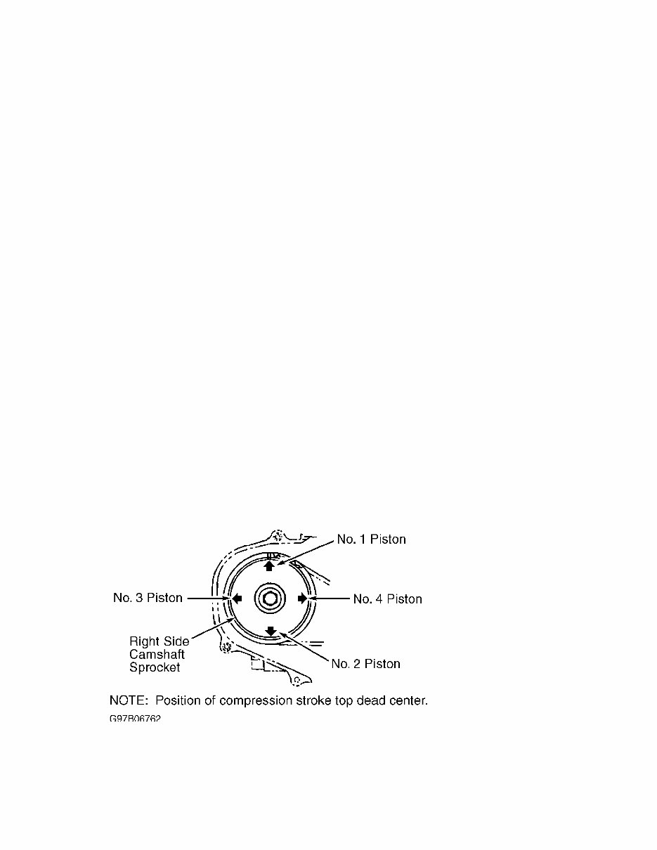
ADJUSTMENTS VALVE CLEARANCE ADJUSTMENT NOTE: Engines on 1995-96 models are equipped with hydraulic lash adjusters. Valve adjustment is not required. NOTE: Perform valve adjustment when engine is cold. 1997-98 Models Disconnect battery ground cable. Remove connector from mass airflow sensor. Remove air intake duct and upper air cleaner cover as a unit. Remove air filter. Disconnect washer fluid pump wire connector and hose. Remove washer fluid tank. Remove right side timing belt cover. Remove spark plug wires. 2) Raise and support vehicle. Remove undercovers. Disconnect PCV hoses and remove valve covers. Set No. 1 cylinder to TDC of compression stroke. Arrow mark on right-side camshaft sprocket should be pointing up. See Fig. 1. Using feeler gauge, measure No. 1 cylinder valve clearance. Adjust as needed. Tighten lock nut to 78-95 INCH lbs. (9-11 N.m). See VALVE CLEARANCE SPECIFICATION. 3) Rotate crankshaft 180 degrees clockwise (camshaft turns 90 degrees) so the next cylinder in firing order is at TDC, and check/adjust valve clearance for that cylinder. See Fig. 1. Repeat procedure until all valves have been adjusted. Fig. 1: Identifying Camshaft/Cylinder Top Dead Center Positions Courtesy of Subaru of America, Inc. VALVE CLEARANCE SPECIFICATION ÄÄÄÄÄÄÄÄÄÄÄÄÄÄÄÄÄÄÄÄÄÄÄÄÄÄÄÄÄÄÄÄÄÄÄÄÄÄÄÄÄÄÄÄÄÄÄÄÄÄÄÄÄÄÄÄÄÄÄÄ Application Clearance In. (mm)
Intake ............................. .0070-.0087 (.18-.22) Exhaust ............................ .0091-.0106 (.23-.27) ÄÄÄÄÄÄÄÄÄÄÄÄÄÄÄÄÄÄÄÄÄÄÄÄÄÄÄÄÄÄÄÄÄÄÄÄÄÄÄÄÄÄÄÄÄÄÄÄÄÄÄÄÄÄÄÄÄÄÄÄ REMOVAL & INSTALLATION * PLEASE READ THIS FIRST * NOTE: For reassembly reference, label all electrical connectors, vacuum hoses and fuel lines before removal. Also place mating marks on engine hood and other major assemblies before removal. FUEL PRESSURE RELEASE 1995-97 Models Disconnect fuel pump wiring connector located under rear seat. Start engine and let idle until it stalls. Crank engine for an additional 5 seconds. Turn ignition off. 1998 Models Disconnect fuel pump relay connector located under left side of dash. Start engine and run until it stalls. Crank engine for an additional 5 seconds. Turn ignition off. ENGINE NOTE: Transaxle remains in vehicle with engine removal. Removal 1) Release fuel pressure. See FUEL PRESSURE RELEASE. Drain cooling system. Disconnect battery and remove from vehicle. Remove air intake duct/upper air cleaner cover assembly. Disconnect radiator and heater hoses. Disconnect A/T cooler lines (if equipped). Remove radiator. 2) Identify, mark and disconnect electrical connectors, vacuum hoses and fuel lines that interfere with engine removal. Discharge A/C system using approved refrigerant recovery/recycling equipment. Disconnect accelerator cable, cruise control cable (if equipped) and clutch cable/hill holder cable at clutch release fork (M/T). 3) Remove accessory drive belts. Remove power steering pump with hoses attached and set aside. Remove hoses from A/C compressor and set aside. Raise and support vehicle. Remove front exhaust pipe. Disconnect engine mount from front crossmember. Remove nuts attaching lower engine to transaxle. 4) Remove all brackets interfering with engine removal.
Remove flywheel access cover. Disconnect bolts securing drive plate to torque converter (A/T). Support engine using hoist. Support transaxle using floor jack. Remove bolts attaching upper side of engine to transmission. Remove engine. Installation To install, reverse removal procedure. Tighten bolts and nuts to specification. See TORQUE SPECIFICATIONS. Adjust all control cables. Check all fluid levels. INTAKE MANIFOLD Removal & Installation 1) Release fuel pressure. See FUEL PRESSURE RELEASE. Remove "V" belt. Disconnect negative battery cable. Remove air intake duct/upper air cleaner cover assembly. Disconnect throttle cable. Disconnect cruise control cable (if equipped). Remove power steering belt. Remove power steering pump with hoses attached and set aside. 2) Disconnect PCV and ventilation hoses. Disconnect spark plug wires. Disconnect coolant hoses and air by-pass hose from throttle body. Disconnect electrical connectors and vacuum hoses interfering with intake manifold removal. 3) Remove EGR pipe. Disconnect fuel hoses from pipes. Remove intake manifold-to-cylinder head bolts. Remove intake manifold. To install, reverse removal procedure. Use NEW gaskets. Tighten bolts to specification. See TORQUE SPECIFICATIONS. EXHAUST MANIFOLD NOTE: Exhaust manifold is integral with cylinder head. CYLINDER HEAD Removal Release fuel pressure. See FUEL PRESSURE RELEASE. Drain engine coolant. Remove timing belt and camshaft sprocket. See TIMING BELT. Remove intake manifold and exhaust pipe. See INTAKE MANIFOLD. Remove cylinder head bolts in reverse order of tightening sequence. See Fig. 2. Remove cylinder head and gasket. Inspection Check cylinder head warpage and height. Resurface head if warpage exceeds specification. See CYLINDER HEAD table under ENGINE SPECIFICATIONS. Replace cylinder head if height is not within specification. Installation Ensure mating surfaces are clean and dry. Install head
gasket. Coat head bolt threads with oil. Tighten bolts to specification in sequence. See Fig. 2. See TORQUE SPECIFICATIONS. To complete installation, reverse removal procedure. Fig. 2: Cylinder Head Bolt Tightening Sequence Courtesy of Subaru of America, Inc. TIMING BELT Removal 1) Remove generator drive belt. Remove A/C belt and tensioner, if equipped. Remove crankshaft pulley. If engine is removed from vehicle, crankshaft can be held using Crankshaft Pulley Wrench (499977000). Fig. 3: Identifying Crankshaft Pulley & Timing Belt Covers Courtesy of Subaru of America, Inc.
If you are in need of a repair manual for your 1998 Subaru Impreza, look no further. Our accessible repair manual software provides comprehensive coverage for the Subaru Impreza, making it an ideal resource for both professional mechanics and DIY enthusiasts.
Gone are the days of purchasing traditional service manuals in book format at a higher cost. Our repair manual software offers the same valuable information in a more affordable and convenient digital format.
Whether you are tackling brake repairs, replacing suspension components, addressing engine issues, or performing standard maintenance, this repair manual software for the Subaru Impreza has you covered. It contains all the necessary service information for brakes, engine, suspension, steering, drivetrain, electrical systems, heating, air conditioning, and more.
By utilizing this 1998 Subaru Impreza repair manual software, you can save a significant amount of money on vehicle maintenance. Professional mechanics often charge high fees for their services, making a DIY approach with our user-friendly manual a cost-effective alternative.
Our repair manual software is compatible with Windows, Mac computers, smartphones, and tablets, ensuring easy access to the manual for your Impreza across various devices.
Recently Viewed
5,521,897Happy Clients
2,594,462eManuals
1,120,453Trusted Sellers
15Years in Business
Price:
Actual Price:
1998 Subaru Impreza Service & Repair Manual Software