

SsangYong Rexton Electrical Wiring Diagram Manual
What's Included?
Fast Download Speeds
Online & Offline Access
Access PDF Contents & Bookmarks
Full Search Facility
Print one or all pages of your manual

HOW TO USE
ELECTRICAL WIRING
DIAGRAM
POSITION OF
CONNECTORS AND
GROUNDS
WIRING DIAGRAM FOR
POWER SUPPLIES
USAGE AND CAPACITY
OF FUSES IN FUSE BOX
ELECTRICAL WIRING
DIAGRAMS
SECTION INDEX
1
2
3
4
5
(LHD)
ELECTRICAL WIRING
DIAGRAM
PYUNGTAEK, KOREA
SSANGYONG MOTOR CO., LTD.

SECTION 1
HOW TO USE ELECTRICAL
WIRING DIAGRAM
TABLE OF CONTENTS
1. HOW TO READ ELECTRICAL WIRING DIAGRAM ................................................... 1-2
2. CIRCUIT IDENTIFICATION SYMBOL ......................................................................... 1-4
3. FUNCTION OF POWER SUPPLY LINE (NUMBER) ................................................. 1-4
4. WIRING HARNESS COLOR IDENTIFICATION .......................................................... 1-4
5. HOW TO CHECK TERMINAL NUMBER OF CONNECTOR ................................... 1-5
6. PART LOCATION ACCORDING TO PART NUMBER .............................................. 1-6
7. ELECTRIC SYMBOLS .................................................................................................. 1-7
8. ABBREVIATIONS ........................................................................................................... 1-8
SSANGYONG REXTON XDi (LHD)
1-2 HOW TO USE ELECTRICAL WIRING DIAGRAM
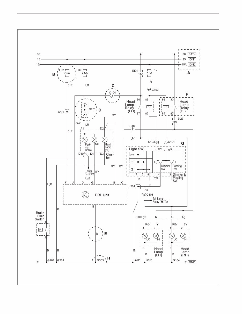
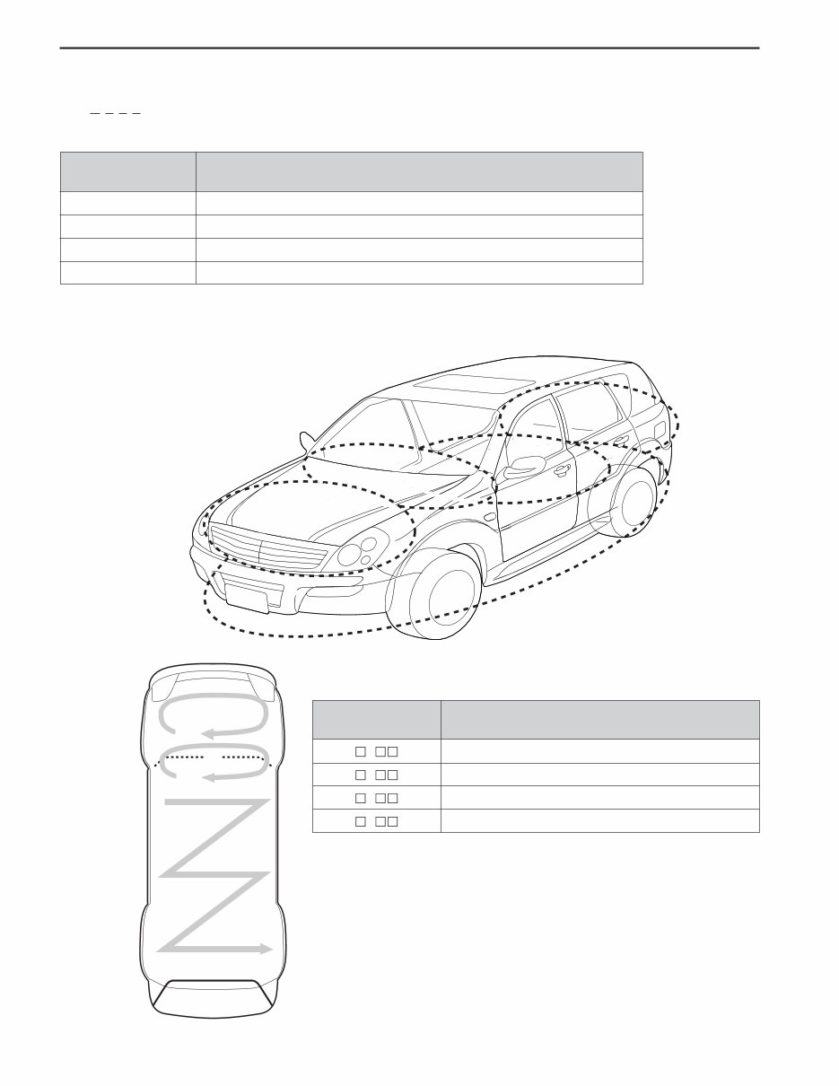
1. HOW TO READ ELECTRICAL WIRING DIAGRAM
HOW TO USE ELECTRICAL WIRING DIAGRAM 1-3
SSANGYONG REXTON XDi (LHD)
- Upper horizontal lines : Power supply lines
- Power supply lines : 30, 15, 15A, 15C, 58
- Ef20 or F2 : Fuse Number
• Ef20 : Fuse No #20 in engine room compartment
• F2 : Fuse No #2 in passenger room compartment
- Connector (C101 ~ C402)
• Connector No C203 terminal No1
* Refer to Major Connector Position (Section 2)
- S201 : Splice pack (S101 ~ S302)
* Refer to Major Splice Pack Position (Section2)
- Wiring Harness Color
* Refer to Wiring Harness Color Abbreviation
- Internal circuit of component (Relay)
(Component Name and Terminal Number)
- Internal circuit of component (Switch)
(Component Name, Terminal Number and Connecting Wiring Circuit)
- Lower horizontal line : Ground line
• Ground position (G101 ~ G401)
• B : Body Ground
* Refer to Major Ground Position (Section2)
A
B
C
D
E
F
G
H
1) CONTENTS OF ELECTRICAL WIRING DIAGRAM (CIRCUIT)
Position Explanation
SSANGYONG REXTON XDi (LHD)
1-4 HOW TO USE ELECTRICAL WIRING DIAGRAM
Battery Voltage (B+) supply in Ignition Switch “ON” and “ST” (IGN 1)
Battery Voltage (B+) supply in Ignition Switch “ON” (IGN 2)
Battery Voltage (B+) supply in Ignition Switch “ON” and “ACC”
Battery Voltage (B+) supply directly regardless of Ignition Switch
Ground connected to battery (-)
Battery Voltage (B+) supply in Head Lamp Switch 1st and 2nd step
(Illumination circuit)
Connector
Diode
Fuse in engine room fuse & relay box
Fuse in passenger room fuse box
Ground
Splice pack (Junction connector)
C
D
Ef
F
G
S
2. CIRCUIT IDENTIFICATION SYMBOL
3. FUNCTION OF POWER SUPPLY LINE (NUMBER)
Identification
Symbol
Meaning
Power supply No. Power supply condition
15
15A
15C
30
31
58
Abbreviation Color
Brown
Green
Violet
Pink
White
Orange
Light Green
Br
G
V
P
W
Or
Lg
Abbreviation Color
Sky Blue
Red
Blue
Yellow
Gray
Black
Sb
R
L
Y
Gr
B
4. WIRING HARNESS COLOR IDENTIFICATION
HOW TO USE ELECTRICAL WIRING DIAGRAM 1-5
SSANGYONG REXTON XDi (LHD)
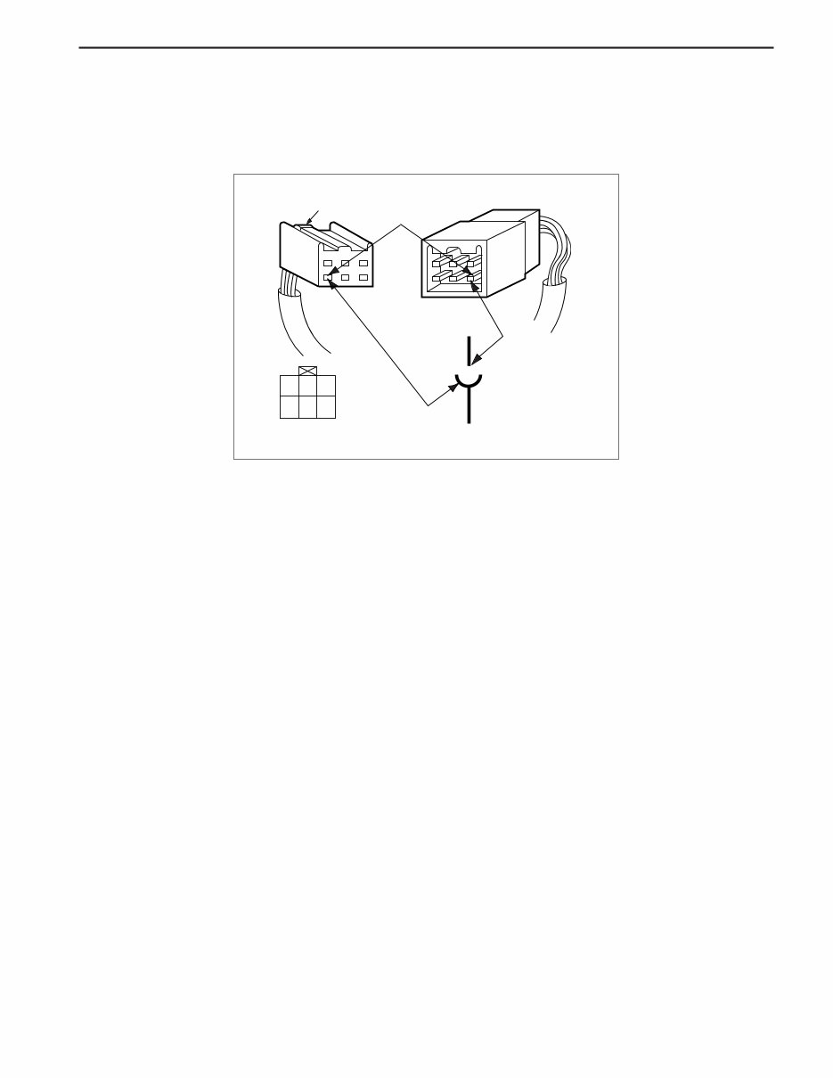
5. HOW TO CHECK TERMINAL NUMBER OF CONNECTOR
- Terminal number is given based on Female Terminal Connector
ex) Terminal Number 4 of C901 connection
Locking
Terminal Number 4
of total 6 pins
Male Connector
(W/H Fuel Tank)
4
C901
Female Connector
(W/H Floor)
C901
W/H Floor
1 3 2
4 6 5
SSANGYONG REXTON XDi (LHD)
1-6 HOW TO USE ELECTRICAL WIRING DIAGRAM
1
1
2
9
9
9
3
3
2
6. PART LOCATION ACCORDING TO PART NUMBER
Ex.) C 1 0 2
• C : Symbol character for connector
Part Number
Engine compartment
Instrument panel
Passenger compartment, Tailgate
Underbody
1
2
3
9
Location
• 1 : Part location number
Symbol Character
Connector (Connecting part that connects two wiring harness)
Diode
Ground
Splice pack (Joint connector that connects various wiring harness)
C
D
G
S
Description
• Part number according to locating section
• In the locating section, the assignment for part number starts from
left bottom and proceeds clockwise.
• In the fuse and relay box or the instrument panel, the part number is
assigned from left top to light bottom.
• 02 : Part number
HOW TO USE ELECTRICAL WIRING DIAGRAM 1-7
SSANGYONG REXTON XDi (LHD)
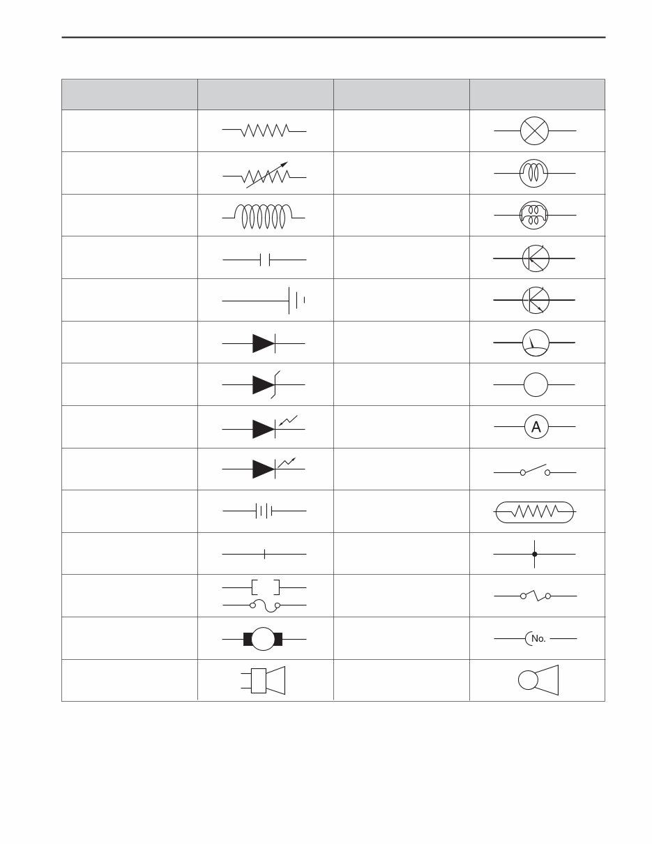
7. ELECTRIC SYMBOLS
Items Symbols Items Symbols
Resistance
Rheostat
Coil, Inductance
Condenser, Capacitor
Ground, Earth
Diode
Zener Diode
Photo Diode
Light Emitting Diode
Battery
Disconnected Wire
Fuse
Motor
Speaker
Lamp
Single Bulb
Double Bulb
Transistor : PNP type
Transistor : NPN type
~Meter, ~Gauge
Voltmeter
Amperemeter
Switch
Thermistor
Junction Point
Fusible Link
Connector
Horn
M
V
SSANGYONG REXTON XDi (LHD)
1-8 HOW TO USE ELECTRICAL WIRING DIAGRAM
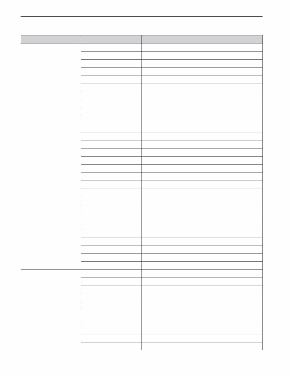
Abbreviations
Air Bag
Air Cleaner
Air Conditioner
Air Duct
Auto Transmission
Automatic Brake Differential
Anti-lock Braking System
Alternating Current
Accessory
Accelerator
Auto Cruise System
Actuator
Alternator
Ampere
Antenna
Anti Slip Regulator
Assembly
Automatic Temperature Controller
After Top Dead Center
Auxiliary
Automatic Voltage Regulator
Battery
Back Up
Back Door
Back Window
Bottom Dead Center
Body in White
Before Top Dead Center
Compressor
Condenser Fan
Connector
Cigar Lighter
Cruise
Crash Pad
Canister
Contact Breaker
Cable
Catalystic Converter
A
B
C
A/BAG
A/CLNR
A/CON (A/C)
A/DUCT
A/T
ABD
ABS
AC
ACC
ACCEL
ACS
ACTR (ACT)
ALT
AMP
ANT
ASR
ASSY
ATC
ATDC
AUX
AVR
BATT
B/UP
B/DR
B/WDW
BDC
BIW
BTDC
COMP
C/FAN
CONN
C/LIGHTER
CRU
C/PAD
CANI
CB
CBL
CC
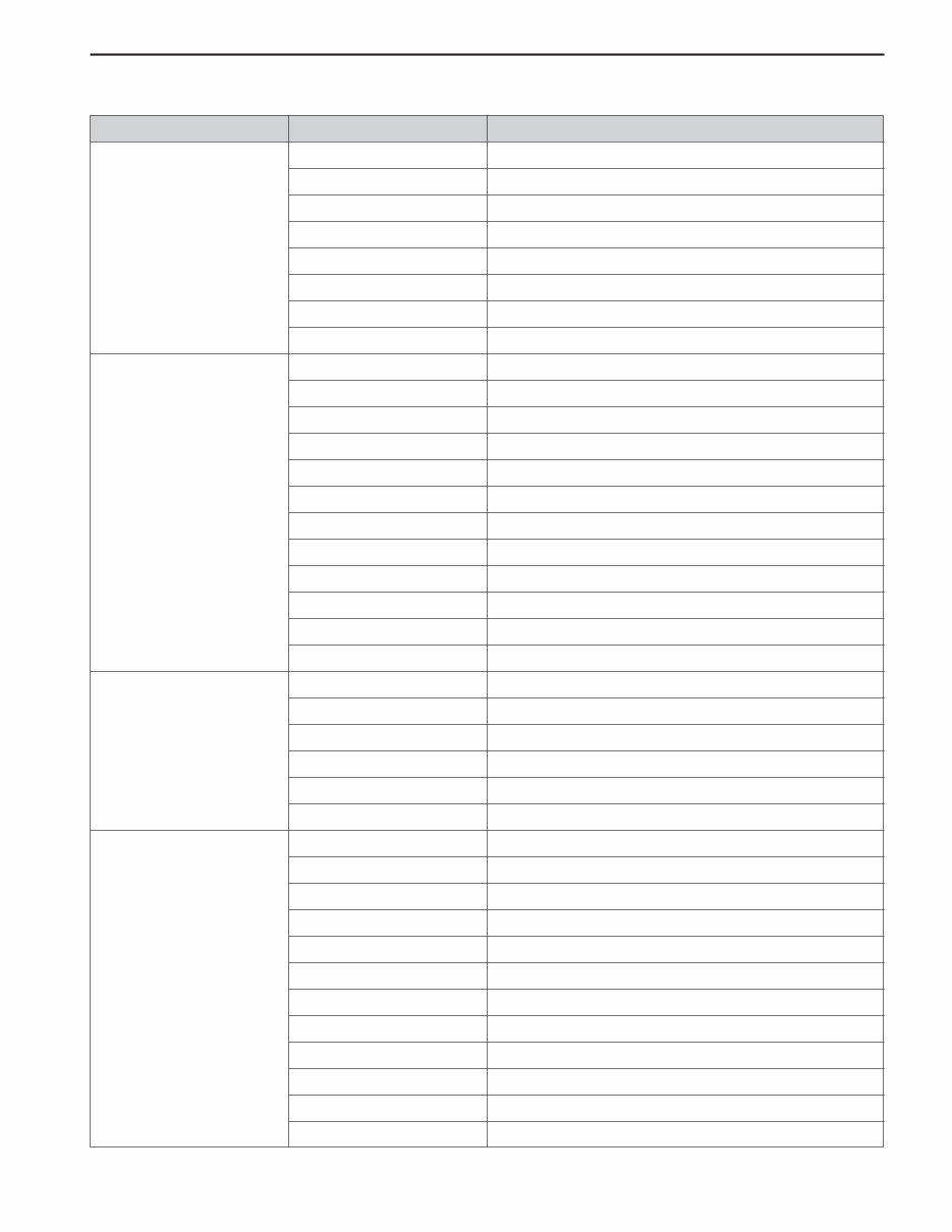
8. ABBREVIATIONS
Classification Full words
HOW TO USE ELECTRICAL WIRING DIAGRAM 1-9
SSANGYONG REXTON XDi (LHD)
Compact Disk - Interactive
Cooling
Clutch
Control
Converter
Coupling
Child Restraint System
Center
Diesel
Door
Down
Door Courtesy
Dimmer Switch
Direct Current
Defogger
Diaphragm
Dynamo
Drawing
Driver
Dual Pressure Switch
Engine
Electronic Control Unit
Exhaust Gas Recirculation System
Engine Spark Control
Electronic Steering & Inside Mirror Control System
Exterior
Frame
Forward
Front Left
Front Right
Fuel Pump
Fluid Leveling
Front
Fusible Link
Fuse Box
Front Door
Front Floor
Front Seat
C
D
E
F
CD-I
CLG
CLH
CONT
CONV
CPLG
CRS
CTR
DSL
DR
DN
D/CTSY
D/SW
DC
DEFOG
DIAPH
DYN
DWG
DRV
D/P SW
ENG
ECU
EGR
ESC
ESIMS
EXTR
FRM
FWD
FL
FR
F/PUMP (F/P)
F/LEVEL’G
FRT
F/LINK
F/BOX
F/DR
F/FLR
F/SEAT
Classification Abbreviations Full words
You're Reading a Preview
What's Included?
Fast Download Speeds
Online & Offline Access
Access PDF Contents & Bookmarks
Full Search Facility
Print one or all pages of your manual
$31.99
$41.99
Viewed 90 Times Today


Secure transaction
What's Included?
Fast Download Speeds
Online & Offline Access
Access PDF Contents & Bookmarks
Full Search Facility
Print one or all pages of your manual
$31.99
$41.99
ELECTRICAL WIRING DIAGRAM FOR LHD REXTON VEHICLES
This manual provides detailed information on how to read electrical wiring diagrams for LHD Rexton vehicles. It includes circuit identification symbols, the function of power supply lines, wiring harness color identification, checking terminal numbers of connectors, part locations according to part numbers, electric symbols, and abbreviations.


