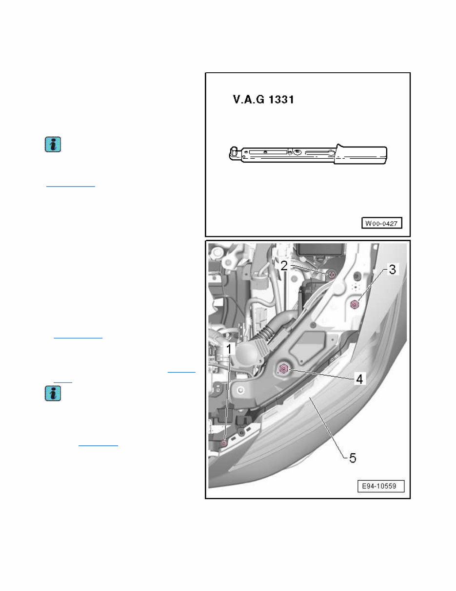
00 Correct the installation position Special tools and workshop equipment required t Torque wrenches -V.A.G 1331- Note Gap and flush fit of the headlight when installing (wing, bumper and bonnet) → Rep. gr.00 – Undo the screws -1, 2, 3 and 4-. – Adjust the height and inclination of the headlights using the hexagon nuts, see → Rep. gr.00 – Tighten screws -1-, -3-, -2- and -4- in this sequence, so that headlight -5- closes flush with the bodywork → Rep. gr.00. Note The adjustment must be carried out following each removal and installation or after correcting the installation position in all cases → Chapter. Page 1 of 1 00 Correct the installation position 4/10/2016 vw-wi://rl/S.en-GB.S01DDXX5F.wi::67311713.xml?xsl=3
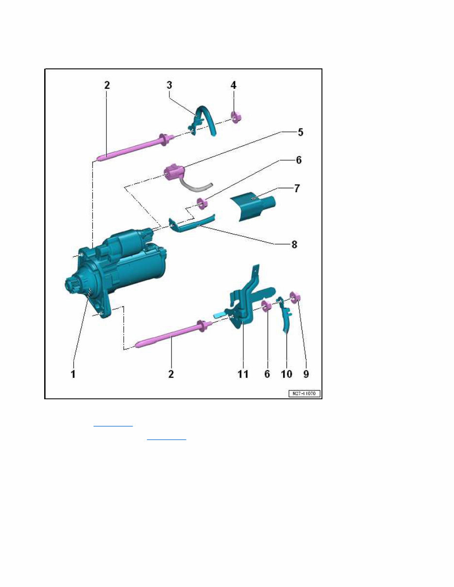
00 Starter, vehicles with manual gearbox 1 - Starter motor: -B- q Checking → Chapter. q Removing and installing → Chapter 2 - Plug q 80 Nm 3 - Earth wire q Depending on equipment 4 - Nut q Depending on equipment q 20 Nm Page 1 of 2 00 Starter, vehicles with manual gearbox 4/10/2016 vw-wi://rl/S.en-GB.S01DDXX5F.wi::67311601.xml?xsl=3
5 - Connector 6 - Nut q 20 Nm 7 - Cap 8 - Terminal 30/B+ 9 - Nut q Depending on equipment q 20 Nm 10 - Earth wire q Depending on equipment 11 - Rear bracket q For the cable harness Page 2 of 2 00 Starter, vehicles with manual gearbox 4/10/2016 vw-wi://rl/S.en-GB.S01DDXX5F.wi::67311601.xml?xsl=3
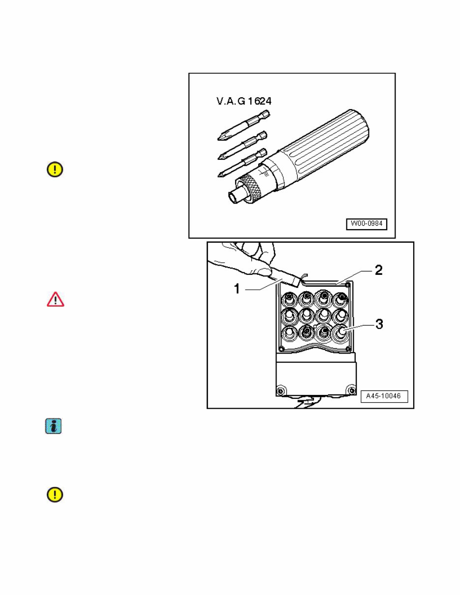
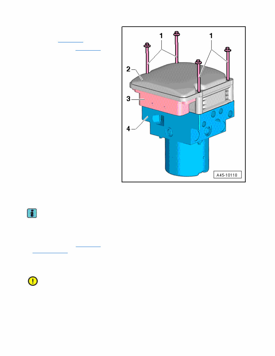
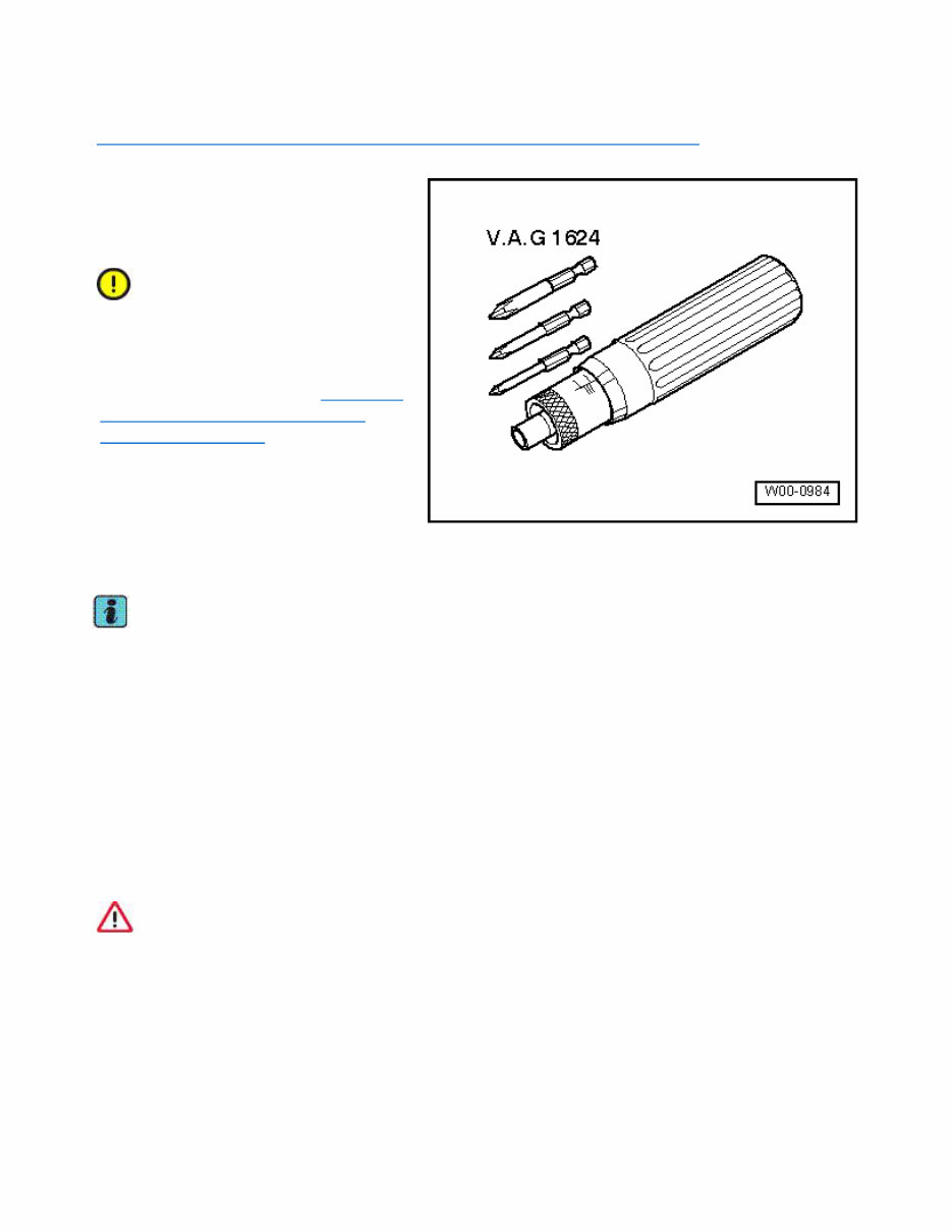
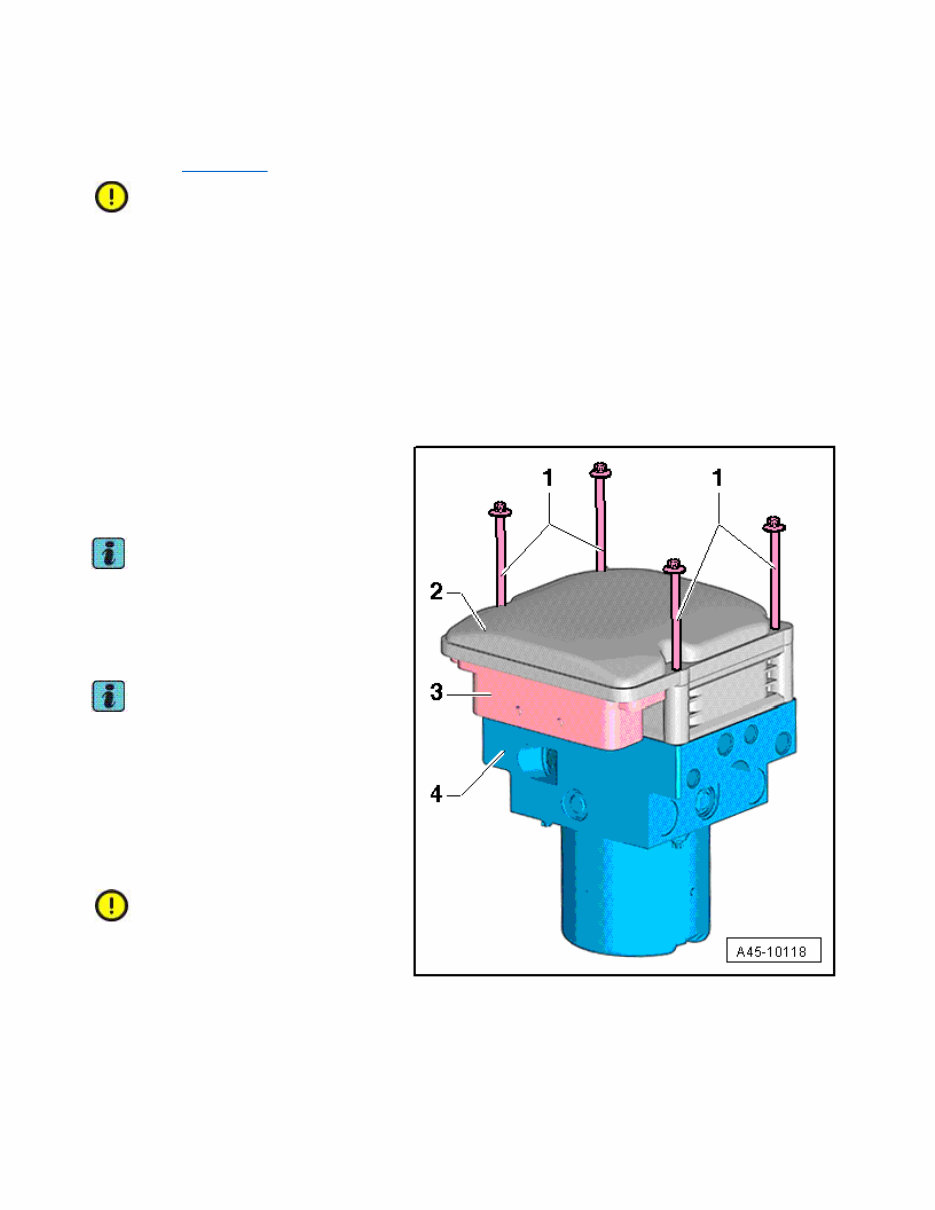
ABS control unit -J104- - connect to the ABS hydraulic unit -N55- Special tools and workshop equipment required t Torque screwdriver -VAG 1624- t ESD workplace -VAS 6613- t Torx socket T25 Caution Use new bolts. – Clean sealing surface on hydraulic unit - 2- using plastic scraper -1-. The contact pins -3- must not be damaged or bent. WARNING The sealing surface on the hydraulic unit must be clean and smooth. The hydraulic unit must be renewed if the sealing surface or the contact lugs are damaged. The seal on the control unit cannot be replaced. The seal on the control unit must not be lifted or pulled out. Note t Use the cleaning agent provided (do not use any aggressive cleaning products). t Check sealing surface for damage (visual inspection). Caution Make sure that no moisture or dirt gets inside the control unit. Do not blow out the control unit or hydraulic unit with compressed air. Page 1 of 4 ABS control unitJ104 - connect to the ABS hydraulic unitN55 4/10/2016 vw-wi://rl/S.en-GB.S01DAXX5F.wi::67487987.xml?xsl=3
Severe shocks or jolts can damage the control unit. The control unit must not be re-installed if it has been damaged in any way. – Check contact pins in hydraulic unit for damage. Caution The hydraulic unit must not be re-used if the contact pins in the hydraulic unit are damaged or bent. Caution The electrical components of the printed circuit can be damaged by static loading. Before working on electric components, touch an earthed object, ESD workplace - VAS 6613-. Do not directly touch connector contacts or electronic components. – Set the hydraulic unit down on the ESD work station -VAS 6613-. The hydraulic unit -4- with the pump motor and connector -3- faces downwards. – Carefully position control unit from above on hydraulic unit with valve coils hanging down. Note t Take care to keep the valve coils straight. t Use new bolts. – Screw in (but do not tighten) the new bolts evenly until the control unit makes uniform contact with the hydraulic unit. – Tighten bolts in diagonal sequence. Tightening torque: 4.5 Nm After screwing on, check: t That all bolts make contact, t That control unit and hydraulic unit make contact all-round. Page 2 of 4 ABS control unitJ104 - connect to the ABS hydraulic unitN55 4/10/2016 vw-wi://rl/S.en-GB.S01DAXX5F.wi::67487987.xml?xsl=3
– Install the hydraulic unit for ABS -N55 - together with the control unit for ABS -J104- → Chapter. – Bleed brake system → Chapter. – With the ignition switched off, connect the vehicle diagnostic unit- Arrow-. – Switch ignition on Note Event memory interrogated, displayed faults rectified and event memory erased. – Start the relevant program in the “Guided Functions” → Vehicle diagnostic tester. After replacing the control unit and bleeding the brake system, all ESP warning lamps must switch off. Caution Before performing the first test drive, make sure that the brakes are operating correctly. A new control unit may be mounted on an existing hydraulic unit max. three times to Page 3 of 4 ABS control unitJ104 - connect to the ABS hydraulic unitN55 4/10/2016 vw-wi://rl/S.en-GB.S01DAXX5F.wi::67487987.xml?xsl=3
guarantee impermeability of the elastic seal. A control unit which has been in operation while the vehicle is being driven must not be fitted a second time. Page 4 of 4 ABS control unitJ104 - connect to the ABS hydraulic unitN55 4/10/2016 vw-wi://rl/S.en-GB.S01DAXX5F.wi::67487987.xml?xsl=3
ABS control unit -J104- - separate from the ABS hydraulic unit -N55- → Chapter „ABS control unit -J104- - connect to the ABS hydraulic unit -N55-“ Special tools and workshop equipment required t Torque screwdriver -VAG 1624- t ESD workplace -VAS 6613- t Torx socket T25 Caution The ABS control unit -J104- and the ABS hydraulic unit -N55- must be removed before they are separated. Note this before replacement → Chapter „Instructions for replacing the ABS hydraulic unit -J104-“. l If a control unit is defective, separate the control unit from the hydraulic unit and renew only the control unit. l If the hydraulic unit is defective, the hydraulic unit must be renewed together with the control unit. Note t Before removing the control unit, read out the event memory and print out the fault code if applicable. t The ESP unit must be removed in order to separate the control unit from the hydraulic unit. t The ESP unit may only be removed by suitably qualified personnel. t The control unit and hydraulic unit may only be separated by suitably qualified personnel. WARNING t Return flow pump must not be separated from hydraulic unit. t The printed circuit board becomes visible when the control unit is removed. t No moisture or particles of dirt may enter control unit. t Avoid electrostatic discharge! Page 1 of 3 ABS control unitJ104 - separate from the ABS hydraulic unitN55 4/10/2016 vw-wi://rl/S.en-GB.S01DAXX5F.wi::67487986.xml?xsl=3
Removal: The hydraulic unit for ABS -N55- must be removed together with the control unit for ABS -J104- → Chapter. Caution The electrical components of the printed circuit can be damaged by static loading. Before working on electric components, touch an earthed object, ESD workplace - VAS 6613-. Do not directly touch connector contacts or electronic components. – Set down hydraulic unit with control unit on ESD work station -VAS 6613-. The control unit -2- faces upwards; the hydraulic unit -4- with the pump motor and connector -3- face downwards. – Slacken off and unscrew bolts -1-. Note t Discard the old bolts immediately. t Never re-use old bolts. – Carefully lift off control unit vertically upwards. Note t Make sure the valve coils do not catch; otherwise they can be distorted by the retainer. t The seal on the control unit cannot be replaced. t The seal on the control unit must not be lifted or pulled out. Caution Cover the open hydraulic unit. Protect the hydraulic unit, sealing surfaces, valve body and pressure sensor against dirt and damage. Do not apply battery voltage to check the pump motor; this can cause scorching on the contacts. Page 2 of 3 ABS control unitJ104 - separate from the ABS hydraulic unitN55 4/10/2016 vw-wi://rl/S.en-GB.S01DAXX5F.wi::67487986.xml?xsl=3
The 2015 SEAT LEON MK3 Service and Repair Manual is a comprehensive guide suitable for professional mechanics and DIY enthusiasts. It provides detailed information and instructions for servicing and repairing the SEAT LEON MK3 model.
This manual covers various models of the SEAT LEON MK3, including:
SEAT LEON MK3 1.2 TSI
SEAT LEON MK3 1.4 TSI
SEAT LEON MK3 1.6 TDI
SEAT LEON MK3 2.0 TDI
SEAT LEON MK3 FR
SEAT LEON MK3 Cupra
Inside the manual, you will find step-by-step instructions, diagrams, and illustrations covering engine maintenance, electrical systems, suspension, brakes, transmission, and more. This resource equips you to confidently perform routine maintenance tasks like oil changes, filter replacements, and brake pad replacements, as well as tackle more complex repairs.
Invest in the 2015 SEAT LEON MK3 Service and Repair Manual today to take control of maintaining your SEAT LEON MK3 with confidence.