

2008 Saturn Vue Service & Repair Manual
What's Included?
Fast Download Speeds
Offline Viewing
Access Contents & Bookmarks
Full Search Facility
Print one or all pages of your manual

2009 Saturn VUE - AWD | VUE, VUE Hybrid (VIN Z), Captiva Sport Service Manual | Brakes | Antilock Brake System |
Specifications | Document ID: 1876598
Fastener Tightening Specifications
Application
Specification
Metric English
Brake Pressure Modulator Valve Bracket Bolts 10 N·m 89 lb in
Brake Pressure Modulator Valve Bracket Nut 10 N·m 89 lb in
Brake Pressure Modulator Valve Bolt 10 N·m 89 lb in
Brake Pipe Fittings 21 N·m 16 lb ft
Electronic Brake Control Module (EBCM) to Brake Pressure Modulator Valve
Bolts
3 N·m 27 lb in
Wheel Speed Sensor Bolt 8 N·m 71 lb in
Yaw Rate Sensor Bolts 8 N·m 71 lb in
© 2010 General Motors Corporation. All rights reserved.
Page 1 of 1 Document ID: 1876598
12/1/2010 http://localhost:9001/si/showDoc.do?docSyskey=1876598&pubCellSyskey=940&pubObj...
2009 Saturn VUE - AWD | VUE, VUE Hybrid (VIN Z), Captiva Sport Service Manual | Brakes | Antilock Brake System |
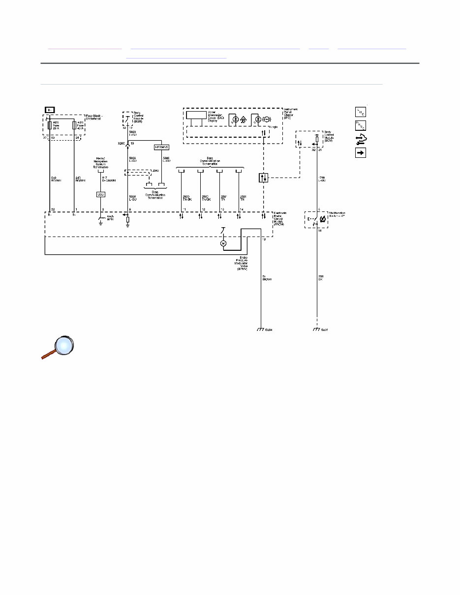
Schematic and Routing Diagrams | Document ID: 2079529
Control Module, Instrument Panel Display and Serial Data
© 2010 General Motors Corporation. All rights reserved.
Page 1 of 1 Document ID: 2079529
12/1/2010 http://localhost:9001/si/showDoc.do?docSyskey=2079529&from=sm
2009 Saturn VUE - AWD | VUE, VUE Hybrid (VIN Z), Captiva Sport Service Manual | Brakes | Antilock Brake System |
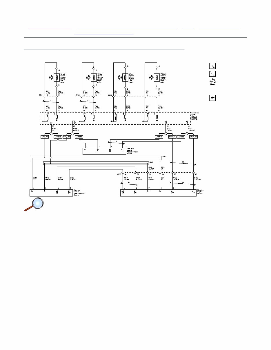
Schematic and Routing Diagrams | Document ID: 2079531
Wheel Speed and YAW/Lateral Speed Sensors
© 2010 General Motors Corporation. All rights reserved.
Page 1 of 1 Document ID: 2079531
12/1/2010 http://localhost:9001/si/showDoc.do?docSyskey=2079531&from=sm

2009 Saturn VUE - AWD | VUE, VUE Hybrid (VIN Z), Captiva Sport Service Manual | Brakes | Antilock Brake System |
Repair Instructions | Document ID: 2165370
Antilock Brake System Automated Bleed Procedure
Warning: Refer to Brake Fluid Irritant Warning in the Preface section.
Caution: Refer to Brake Fluid Effects on Paint and Electrical Components Caution in the Preface
section.
Note: Before performing the antilock brake system (ABS) Automated Bleed Procedure, first
perform a manual or pressure bleed of the base brake system. Refer to Hydraulic Brake System
Bleeding . The automated bleed procedure is recommended when one of the following conditions
exist:
The ABS Automated Bleed Procedure uses a scan tool to cycle the system solenoid valves and run
the pump in order to purge any air from the secondary circuits. These circuits are normally closed
off, and are only opened during system initialization at vehicle start up and during ABS operation.
The automated bleed procedure opens these secondary circuits and allows any air trapped in these
circuits to flow out toward the brake corners.
Automated Bleed Procedure
Caution: The Auto Bleed Procedure may be terminated at any time during the process by
pressing the EXIT button. No further Scan Tool prompts pertaining to the Auto Bleed
procedure will be given. After exiting the bleed procedure, relieve bleed pressure and
disconnect bleed equipment per manufacturers instructions. Failure to properly relieve
pressure may result in spilled brake fluid causing damage to components and painted
surfaces.
1. Raise and support the vehicle. Refer to Lifting and Jacking the Vehicle .
2. Remove all 4 tire and wheel assemblies. Refer to Tire and Wheel Removal and Installation .
3. Inspect the brake system for leaks and visual damage. Refer to Symptoms - Hydraulic
Brakes . Repair or replace components as needed.
4. Lower the vehicle.
5. Inspect the battery state of charge. Refer to Battery Inspection/Test .
6. Install a scan tool.
7. Turn the ignition ON, with the engine OFF.
8. With the scan tool, establish communications with the ABS system. Select Special Functions.
Select Automated Bleed from the Special Functions menu.
9. Raise and support the vehicle. Refer to Lifting and Jacking the Vehicle .
10. Following the directions given on the scan tool, pressure bleed the base brake system. Refer
to Hydraulic Brake System Bleeding .
11. Follow the scan tool directions until the desired brake pedal height is achieved.
12. If the bleed procedure is aborted, a malfunction exists. Perform the following steps before
resuming the bleed procedure:
• Base brake system bleeding does not achieve the desired pedal height or feel
• Extreme loss of brake fluid has occurred
• Air ingestion is suspected in the secondary circuits of the brake modulator assembly
• If a DTC is detected, refer to Diagnostic Trouble Code (DTC) List - Vehicle and diagnose
the appropriate DTC.
• If the brake pedal feels spongy, perform the conventional brake bleed procedure again.
© 2010 General Motors Corporation. All rights reserved.
Page 1 of 2 Document ID: 2165370
12/1/2010 http://localhost:9001/si/showDoc.do?docSyskey=2165370&pubCellSyskey=1238&pubObj...

13. When the desired pedal height is achieved, press the brake pedal to inspect for firmness.
14. Lower the vehicle.
15. Remove the scan tool.
16. Install the tire and wheel assemblies. Refer to Tire and Wheel Removal and Installation .
17. Inspect the brake fluid level. Refer to Master Cylinder Reservoir Filling .
18. Road test the vehicle while inspecting that the pedal remains high and firm.
Refer to Hydraulic Brake System Bleeding .
Page 2 of 2 Document ID: 2165370
12/1/2010 http://localhost:9001/si/showDoc.do?docSyskey=2165370&pubCellSyskey=1238&pubObj...
You're Reading a Preview
What's Included?
Fast Download Speeds
Offline Viewing
Access Contents & Bookmarks
Full Search Facility
Print one or all pages of your manual
$36.99
$48.99
Viewed 29 Times Today


Secure transaction
What's Included?
Fast Download Speeds
Offline Viewing
Access Contents & Bookmarks
Full Search Facility
Print one or all pages of your manual
$36.99
$48.99
Discover the essential 2008 Saturn Vue Service & Repair Manual, a valuable resource for professional mechanics and DIY enthusiasts alike. This comprehensive manual equips you with detailed instructions and illustrations to effectively maintain, repair, and service all 2008 Saturn Vue models.
- Complete coverage for all 2008 Saturn Vue models
- Step-by-step procedures for routine maintenance
- Detailed troubleshooting guides for issue resolution
- Clear and concise wiring diagrams for easy understanding
- Comprehensive specifications and torque values
- Diagnostic codes and explanations
- Repair procedures for engine, transmission, suspension, brakes, electrical systems, and more
Empower yourself with the knowledge and confidence to handle any automotive task that comes your way. Keep your Saturn Vue running smoothly and efficiently with the 2008 Saturn Vue Service & Repair Manual.


