87H-2 V1 MR-456-X09-87H000$010.mif 87H BCB Vdiag No.: 04 1. Fault finding – Introduction 1.1 Document applicability This document presents the fault finding method applicable to all computers with the following specifications: 1.2 Prerequisites for fault finding Documentation type Fault finding procedures for the instrument panel: – Assisted fault finding (integrated into the diagnostic tool), Dialogys. Wiring Diagrams: – Visu-Schéma. Type of diagnostic tools – CLIP Special tooling required If the information obtained by the diagnostic tool requires the electrical continuity to be checked, connect bornier Elé. 1622 or universal bornier Elé. 1681. Vehicle(s): TWIZY Name of computer: charger Function concerned: charger/converter Vdiag No.: 04 Special tooling required: Diagnostic tool Multimeter Elé. 1622 Bornier Elé. 1681 Universal bornier WARNING: – All checks using bornier Elé. 1622 or Elé. 1681 must be performed with the battery disconnected. – The bornier is only designed to be used with a multimeter. Never power the test points with 12 V. Additional adaptation unit Fault finding - Replacement of components
87H-3 V1 MR-456-X09-87H000$010.mif Additional adaptation unit Fault finding - Replacement of components 87H BCB Vdiag No.: 04 1.3 Reminders Procedure To run diagnostics on the vehicle computers, switch on the ignition using the key. Faults Faults are declared present or stored (depending on whether they appeared in a certain context and have disappeared since, or whether they remain present but are not diagnosed within the current context). The present or stored fault status must be considered, when the diagnostic tool is used after switching on the + after ignition feed (without operating the system components). For a present fault, apply the procedure described in the Interpretation of faults section. For a stored fault, note the faults displayed and apply the Notes section. If the fault is confirmed when the instructions are applied, the fault is present. Deal with the fault. If the fault is not confirmed, check: – the electrical lines which correspond to the fault, – the connectors on these lines (corrosion, bent pins, etc.), – the resistance of the faulty component, – the condition of the wires (melted or cut insulation, wear). Conformity check The conformity check is designed to check the statuses and parameters that do not display any faults on the diagnostic tool when they are inconsistent. Therefore, this stage is used to: – carry out fault finding on faults that do not have a fault display, and which may correspond to a customer complaint, – check that the system is operating correctly and that there is no risk of a fault recurring after repair. This section gives the fault finding procedures for statuses and parameters and the conditions for checking them. If a status is not behaving normally or a parameter is outside permitted tolerance values, you should consult the corresponding fault finding page. Customer complaints - Fault finding chart If the test with the diagnostic tool is OK but the customer complaint is still present, the fault should be dealt with by customer complaints. A summary of the overall procedure to follow is provided on the following page in the form of a flow chart.
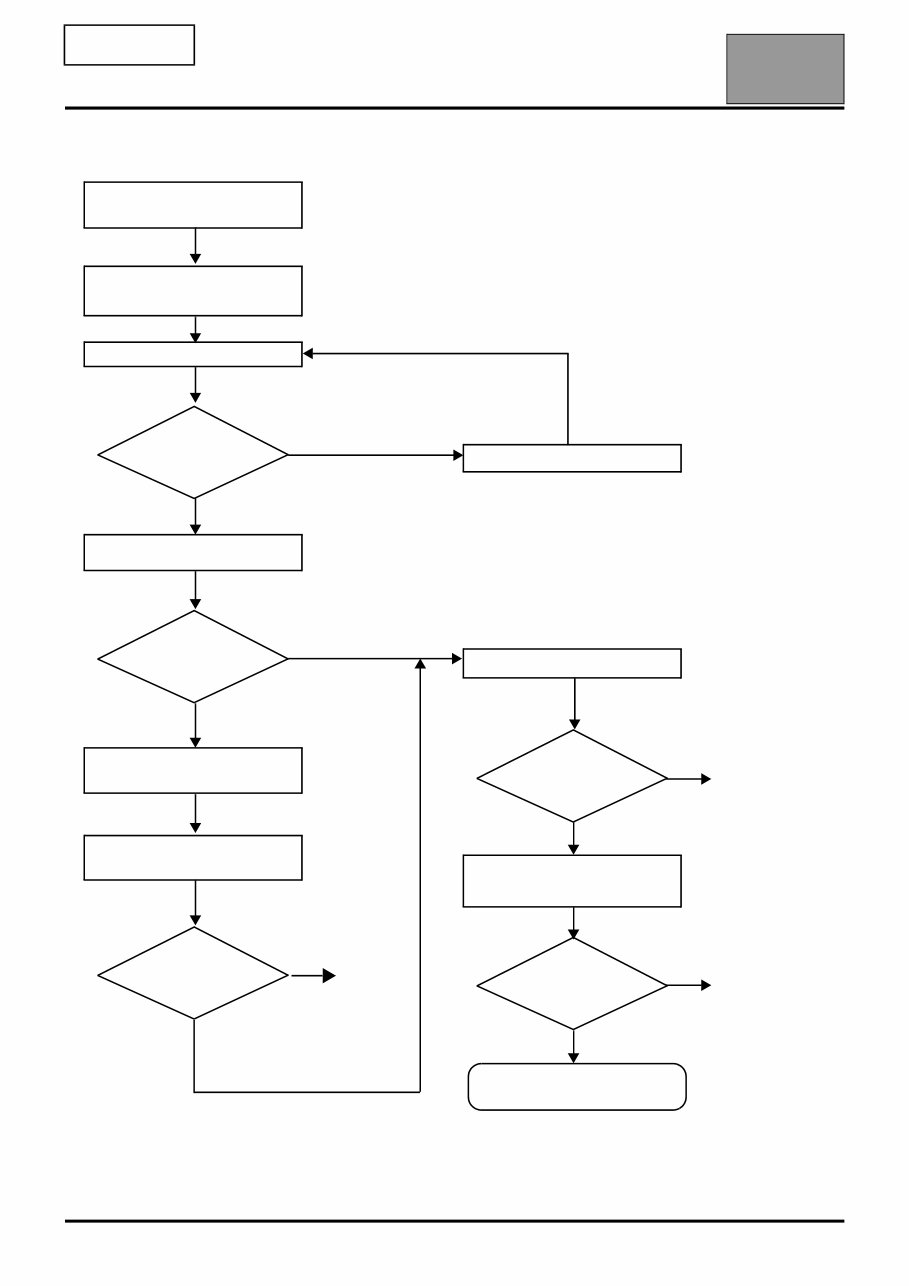
87H-4 V1 MR-456-X09-87H000$010.mif Additional adaptation unit Fault finding - Replacement of components 87H BCB Vdiag No.: 04 1.4 Fault finding procedure Check the battery charge and the condition of the fuses Print the system fault finding log (available on CLIP) Connect CLIP See ALP no. 1 Read the faults Deal with present faults Deal with stored faults Conformity check Use fault finding charts (ALPs) Dialogue with computer? Faults present The cause is still present The cause is still present The cause is still present Contact the Techline with the completed fault finding log no no no no no yes yes yes Fault solved Fault solved Fault solved
87H-5 V1 MR-456-X09-87H000$010.mif Additional adaptation unit Fault finding - Replacement of components 87H BCB Vdiag No.: 04 Wiring check Fault finding problems Disconnecting the connectors and/or manipulating the wiring may temporarily clear the cause of a fault. Electrical measurements of voltage, resistance and insulation are generally correct, especially if the fault is not present when the analysis is made (stored fault). Visual inspection of the connection: • Check that the connector is connected correctly and that the male and female parts of the connection are correctly coupled. Visual inspection of the area around the connection: • Check the condition of the mounting (pin, strap, adhesive tape, etc.) if the connectors are attached to the vehicle. • Check that there is no damage to the wiring trim (sheath, foam, adhesive tape, etc.) near the wiring. • Check that there is no damage to the electrical wires at the connector outputs, in particular on the insulating material (wear, cuts, burns, etc.). Note: Carry out each requested check visually. Do not remove a connector if it is not required. Note: Repeated connections and disconnections alter the functionality of the connectors and increase the risk of poor electrical contact. Limit the number of connections/disconnections as much as possible. Note: The check is carried out on the 2 parts of the connection. There may be two types of connection: – Connector / Connector – Connector / Device
87H-6 V1 MR-456-X09-87H000$010.mif Additional adaptation unit Fault finding - Replacement of components 87H BCB Vdiag No.: 04 Disconnect the connector to continue the checks. Visual inspection of the plastic casing: • Check that there is no mechanical damage (casing crushed, cracked, broken, etc.), in particular to the fragile components (lever, lock, openings, etc.). • Check that there is no heat damage (casing melted, darker, deformed, etc.). • Check that there are no stains (grease, mud, liquid, etc.). Visual inspection of the metal contacts: (The female contact is called CLIP. The male contact is called TAB.) • Check that there are no bent contacts (the contact is not inserted correctly and can come out of the back of the connector). The spring contact of the connector when the wire is gently pulled. • Check that there is no damage (folded tabs, clips open too wide, blackened or melted contact, etc.). • Check that there is no oxidation on the metal contacts. Visual inspection of the sealing: (Only for watertight connectors) • Check for the seal on the connection (between the 2 parts of the connection). • Check the seal at the back of the connectors: • For unit joints (1 for each wire), check that the unit joints are present on each electrical wire and that they are correctly positioned in the opening (level with the housing). Check that plugs are present on openings which are not used. • For a grommet seal (one seal which covers the entire internal surface of the connector), check that the seal is present. • For gel seals, check for gel in all of the openings without removing the excess or any protruding sections (it does not matter if there is gel on the contacts). • For hotmelt sealing (heat-shrink sheath with glue), check that the sheath has contracted correctly on the rear of the connectors and electrical wires, and that the hardened glue comes out of the side of the wire. • Check that there is no damage to any of the seals (cuts, burns, significant deformation, etc.). If a fault is detected, repair or replace the wiring (see Technical Note 6015A, Electrical wiring repair, Wiring: Precautions for repair).
87H-7 V1 MR-456-X09-87H000$010.mif Additional adaptation unit Fault finding - Replacement of components 87H BCB Vdiag No.: 04 1.5 Fault finding log You will always be asked for this log: – when requesting technical assistance from the Techline, – when requesting approval before replacing parts for which approval is compulsory, – to be attached to monitored parts for which reimbursement is requested. The log is needed for warranty reimbursement, and enables better analysis of the parts removed. IMPORTANT! IMPORTANT All faults involving a complex system call for thorough diagnostics with the appropriate tools. The FAULT FINDING LOG, which should be completed during the fault finding procedure, ensures a record is kept of the procedure carried out. It is an essential document when consulting the manufacturer. IT IS THEREFORE MANDATORY TO FILL IN A FAULT FINDING LOG EACH TIME IT IS REQUESTED BY TECHLINE OR THE WARRANTY RETURNS DEPARTMENT.
87H-8 V1 MR-456-X09-87H000$010.mif Additional adaptation unit Fault finding - Replacement of components 87H BCB Vdiag No.: 04 1.6 Safety instructions The safety instructions must be followed at all times when working on components, to avoid damage or injury: – make sure that the battery is properly charged to avoid damaging the computers in the event that it has a low charge, – The drive system of an electric vehicle uses a direct current of approximately 60 volts. This system may be hot during and after switching off the ignition. Respect the warning messages on the labels present inside the vehicle. The electric circuit can be recognised by the orange colour wiring and the components marked with the symbol . – Use the appropriate tools: – Remove all metal jewellery (wedding rings, bracelets, watches) or any item likely to be a conductor.
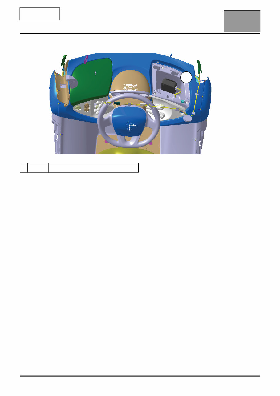
87H-9 V1 MR-456-X09-87H000$020.mif 87H BCB Vdiag No.: 04 The system is made up of the following components: – An additional adaptation unit – A car club computer that is connected to the additional adaptation unit 1 BAC Additional adaptation unit 1 Additional adaptation unit Fault finding - List and location of components
Get your hands on the 2012 Renault Twizy Service and Repair Manual, your go-to resource for fixing vehicle issues. Whether you're a professional mechanic or a DIY enthusiast, these auto repair manuals provide comprehensive instructions and procedures to help you tackle car problems with ease. With customer support available via email, you can count on getting the assistance you need to get your car back on the road. The manual covers a wide range of sections including maintenance, engine, control system, mechanical, fuel service specifications, and much more. It contains detailed technical data, diagrams, and a complete list of car parts, making it suitable for both novice and experienced car mechanics. The manual is available in .PDF format, ensuring compatibility with Windows and Mac operating systems. It's a valuable resource that can save you time and money, allowing you to take on car repairs with confidence. With its user-friendly format, you can easily print the specific pages and diagrams you require, keeping your manual clean and organized for future use. Take advantage of this comprehensive manual to enhance your car repair knowledge and keep your vehicle in top condition.