ELECTRICAL WIRING REPAIR Contents Page 88A 88B 88C WIRING Wiring: Precautions for repair 88A-1 Wiring repair kit: General information 88A-8 Wiring repair kit: Description 88A-9 Wiring repair kit: Use 88A-12 Wiring: Repair 88A-18 Wiring: Check 88A-27 Connector: Repair 88A-30 Connector: Sealing and immobilisation 88A-34 Connector: Check 88A-36 MULTIPLEXING Multiplex network: Repair 88B-1 AIRBAGS AND PRETENSIONERS Airbag and pretensioner wiring: Repair 88C-1
WIRING Wiring: Precautions for repair 88A 188A WIRING Wiring: Precautions for repair 1 - Result of the fault finding procedure. A preliminary fault finding procedure has enabled a wiring fault to be identified. Follow the investigation procedure below. Disconnect the battery (see the MR corresponding to the vehicle, 80A, Battery, Battery: Removal - Refitting). Remove the components necessary to access the area to be worked on. The operation area must allow the pliers and the heat gun to be used, without blocking visibility. When the damaged section is sufficiently accessible, detach the wires to be repaired from the main wiring. Check that the fault is located more than 10 cm from the connector. This note does not authorise operations directly on the connectors and electrical contacts. Only wiring-connector kits allow the replacement of a connector. These kits can have associated procedures. After having carried out these checks (outlined in the Summary flowchart of the operating procedure), if the repair is authorised, and it does not require a specific procedure, carry out the generic procedure (see Wiring: Repair). WARNING This note authorises the repair of electrical wiring in very specific cases only and under certain conditions. Check that the repair in question is authorised and that the repair conditions are respected. Note: During repair, check that you have the most recently updated version of the technical note. WARNING If the damaged section is not sufficiently accessible, remove the wiring concerned and repair on the bench. WARNING Check if there is a sensitive line. These cases are listed in the specific procedures reference table in this section. If there is a sensitive line, replace the defective wiring or apply the specific procedure, if one exists. These procedures are indicated in the specific procedures reference table in this section. WARNING If the damaged section is located less than 10 cm from the connector, replace the defective wiring, unless a wiring-connector kit (connector with wires) exists. In this case, use the kit to replace the damaged section and the connector. Note: To check whether there is a wiring-connector kit, consult DIALOGYS. These kits are generally linked to specific wiring or function diagrams. Note: If the fault is located at the electrical contact (in the connector) and if it is linked to a corrosion or heating fault, replace the wiring or fit the wiring-connector kit. Also check the connector complement. Note: In all cases, pay particular attention to supply and earth lines and their tightening (refer to the tightening torques in the MRs concerned). Note: If you have been referred to this note by a MR, NT or removal-refitting procedure, apply the repair procedure adapted to the case in question. Either the generic repair procedure (see Wiring: Repair), or a specific procedure listed in the specific procedures reference table in this section. 88A-1
WIRING Wiring: Precautions for repair 88A 88A-2 2 - Specific procedures reference table. ● Guidelines for reading the tables below: – If not otherwise stated, consider all components or electrical connections to have a link with the functions or equipment listed. For example: For the electric power assisted steering, the function is not specified. It is prohibited to carry out operations on any wire attached to the electric power assisted steering. – If one case can be found in both tables, give priority to the Changing the wiring, recommendations, and then to those for the specific cases: ● Example 1: For a 22-track airbag connector where more than 10 wires are damaged, the specific cases refer you back to the airbag and pretensioner repair procedure, and the general cases recommend that the wiring is replaced (as there are more than 10 wires involved). Priority is given to Changing the wiring. ● Example 2: For an operation on a pair of twisted wires (general case) for the airbag function (specific case), the specific case refers back to the repair procedure for Airbags and pretensioners, and the general cases refer back to the repair procedure for multiplex lines. Priority is given to the airbag and pretensioner repair procedure. The recommendations for the specific cases take precedent over the general cases.
WIRING Wiring: Precautions for repair 88A 88A-3 ● General cases: Functions or equipment Precisions Instructions Wiring harness Number of damaged wires 10 or fewer (see Wiring: Repair) Number of damaged wires more than 10 Change the wiring Equipment and predispositions specific to commercial vehicles and conversions / Change the wiring Electric vehicles Wiring and power connectors Change the wiring Connections or associated components / (see Connector: Repair) Splices Splice with more than 3 wires Change the wiring 3-wire splice which does not need sealing (see Wiring: Repair) Splice with 3 wires or more, which needs sealing (engine and underbody areas and damp areas of the doors and boot) Change the wiring Wires outside the loom Sheathed wires Change the wiring Shielded wires Change the wiring Twisted wires If the wire cross-sections are 0.5 mm 2 : (see Multiplex network: Repair) Flat cable Change the wiring Wires with specific thermal protection Change the wiring Copper wires with cross-section less than 0.35 mm 2 Change the wiring Copper wires with cross-section greater than 6 mm 2 Change the wiring Damaged wires less than 10 cm from the connector (see 88A, Wiring, Connector: Repair)
WIRING Wiring: Precautions for repair 88A 88A-4 ● Specific cases: Lines Device Instructions 4-wheel steering / Change the wiring ABS Other ABS lines Change the wiring ABS ABS sensor Change the wiring Airbag Other airbag lines (see Airbag and pretensioner wiring: Repair) Airbag Airbag sensor (see Airbag and pretensioner wiring: Repair) Airbag Airbag computer connector (see Airbag and pretensioner wiring: Repair) Airbag Pretensioner (squib) connector (see Airbag and pretensioner wiring: Repair) Airbag Under seat connector (see Airbag and pretensioner wiring: Repair) Airbag Airbag trigger connectors (pyrotechnic lines) (see Airbag and pretensioner wiring: Repair) Preheating unit (Diesel) Heater plug Change the wiring Injection computer (Petrol) Petrol vapour absorber Change the wiring Injection computer Variable camshaft Change the wiring Injection computer Variable inlet camshaft Change the wiring Injection computer Variable exhaust camshaft Change the wiring Injection computer (Petrol) Pencil coil Change the wiring Injection computer (Petrol and Diesel) Motorised throttle body Change the wiring Injection computer Camshaft sensor Change the wiring Injection computer (Petrol and Diesel) Inlet camshaft sensor Change the wiring Injection computer (Petrol and Diesel) Exhaust camshaft sensor Change the wiring Injection computer Camshaft sensor, row A, B Change the wiring Injection computer Variable exhaust camshaft sensor Change the wiring Injection computer (Petrol and Diesel) Pinking sensor Change the wiring Injection computer (Diesel) Turbine upstream pressure sensor Change the wiring
WIRING Wiring: Precautions for repair 88A 88A-5 ● Specific cases (cont. 1): *OTS: Special Technical Operation Lines Device Instructions Injection computer (Petrol) Manifold pressure sensor Change the wiring Injection computer (Diesel) Particle filter differential pressure sensor Change the wiring Injection computer (Diesel) Rail pressure sensor Change the wiring Injection computer (Petrol and Diesel) Turbocharging pressure sensor Change the wiring Injection computer Accelerator pedal sensor Change the wiring, except for the connector on KANGOO (see Connector: Repair) Injection computer (Petrol and Diesel) TDC sensor See OTS* Injection computer (Diesel) Particle filter (downstream) output sensor Change the wiring Injection computer (Petrol and Diesel) Air temperature sensor Change the wiring Injection computer (Petrol) Turbine upstream temperature sensor Change the wiring Injection computer (Diesel) Fuel temperature sensor Change the wiring Injection computer (Petrol and Diesel) Coolant temperature sensor Change the wiring Injection computer (Diesel) Particle filter inlet temperature sensor (upstream) Change the wiring Injection computer (Diesel) Injection air flowmeter Change the wiring Injection computer Camshaft shift, row A, B Change the wiring Injection computer (Diesel) Turbocharger control solenoid valve Change the wiring Injection computer (Diesel) Damper solenoid valve Change the wiring Injection computer (Petrol and Diesel) Injectors Change the wiring Injection computer (Diesel) Diesel heater Change the wiring Injection computer (Diesel) Water in diesel sensor Change the wiring
WIRING Wiring: Precautions for repair 88A 88A-6 ● Specific cases (cont. 2): Lines Device Instructions Injection computer (Diesel/particle filter) Oil level and temperature sensor Change the wiring Injection computer (Diesel) Nitrogen oxide (Nox) Change the wiring Injection computer (Petrol and Diesel) Upstream oxygen sensor Change the wiring Injection computer (Petrol and Diesel) Downstream oxygen sensor Change the wiring Injection computer (Diesel) Proportional oxygen sensor Change the wiring Injection computer (Diesel) EGR valve Change the wiring Injection computer (Diesel) Heater plug Change the wiring EPAS / Change the wiring ETC (4x4 torque distributor) / Change the wiring GMV GMV Change the wiring Multiplex network CAN (See Multiplex network: Repair) UPC (Petrol and diesel) Air conditioning compressor Change the wiring UPC (Petrol) Oil level sensor Change the wiring
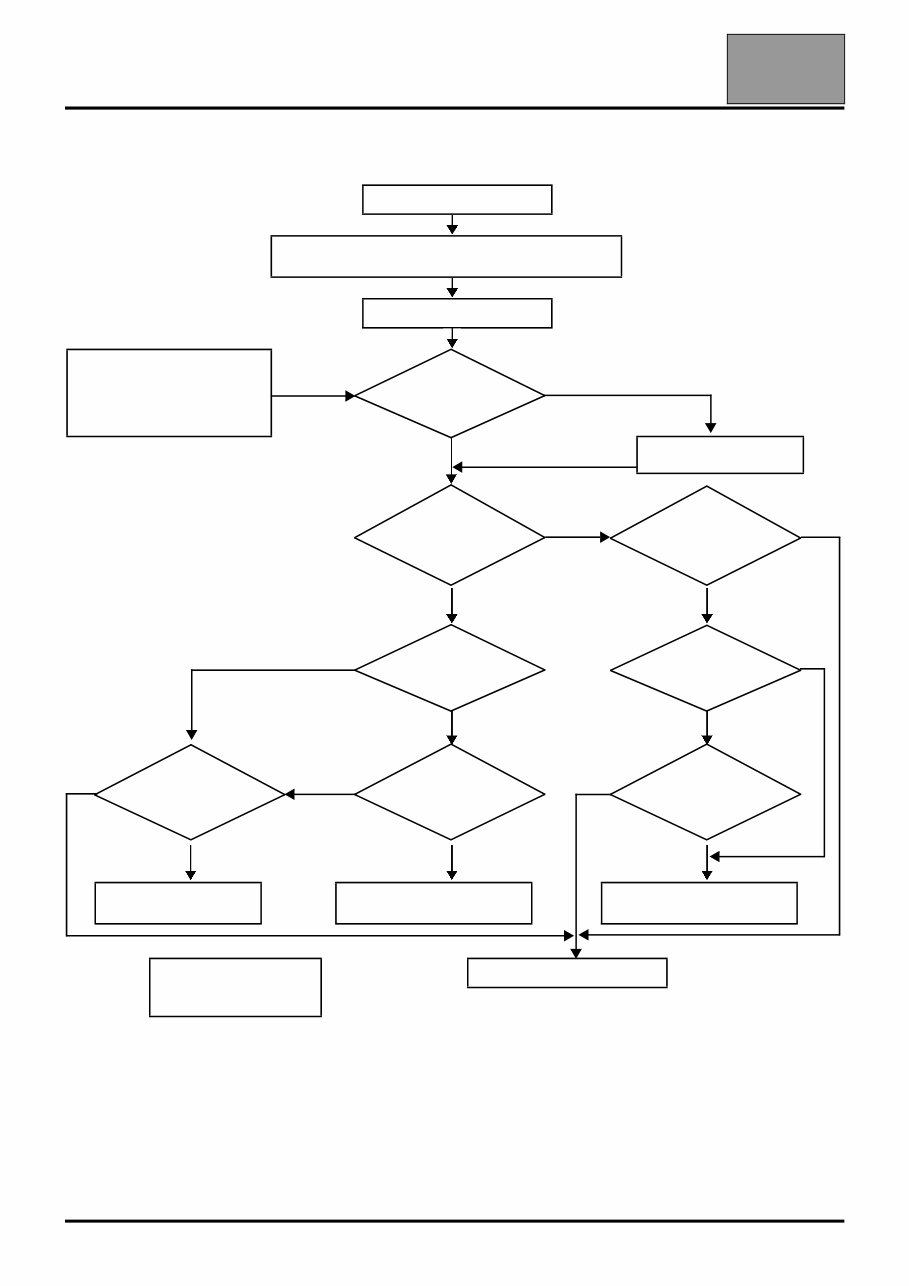
WIRING Wiring: Precautions for repair 88A 88A-7 3 - Summary flowchart of the operating procedure defined in this section. Identify a fault on the wiring. Disconnect the battery (see MR corresponding to the vehicle, 80A, Battery, Battery: Removal - Refitting) Access the area concerned. Case of referral to Technical Note 6015A from a MR, a Technical Note or a removal- refitting procedure. NO Sufficient accessibility? YES Remove the wiring. YES NO Fault on a sensitive line or equivalent? (see table*) Is there a specific procedure? (see table*) NO YES YES YES Caused by connector? Is there a specific kit? (DIALOGYS) NO NO NO NO NO Is there a connector kit? (DIALOGYS) Fault more than 10 cm from the connector? Fault more than 10 cm from the connector? YES YES YES Procedure attached to connector kit. (see table*) Generic repair procedure. (see Wiring: Repair) Specific repair procedure. (see table*) table*: Specific procedures reference table Change the wiring
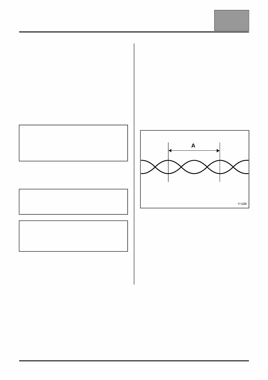
WIRING Wiring repair kit: General information 88A 88A-8 Wiring repair kit: General information 1 - Purpose and applications. Description of the content of the Wiring repair kit case as well as the procedure and the field of application. The kit enables wiring which is damaged or has cut electrical wires to be repaired whilst ensuring that it will be fully functional. It also allows wiring-connector kits to be used. All electrical cables and wires with cross-sections between 0.35 mm 2 and 6 mm 2 except "sensitive lines" (defined in this document), are affected. The technical nature and the sensitivity of this type of operation requires the adapted equipment contained and described in the Wiring repair kit case. 2 - Terminology. ● Wiring-connector kit. Kit usually made up of a connector the cells of which are populated with crimped wires along with sleeves for joining. ● Multiplex lines or connections. Principal or secondary CAN network lines link the computers together and are made up of twisted pairs of stranded wires. ● Turns or twists. For twisted pairs: One turn (twist) = (A) 3 - Operation time (TM). For each vehicle, an average repair time is given in the wiring section of the TM. The corresponding codes are: – 0500 for replacing a connector (using a connector kit). – 0501 for repairing wiring. This times do not include the time taken to access the area to be repaired. The time taken to remove and refit the wiring must be added. WARNING Repair of sensitive lines is prohibited using the generic procedure alone. It can be authorised provided that there is an additional appropriate procedure (see Wiring: Precautions for repair). WARNING Using tools or components which have not been recommended is strictly forbidden when repairing wiring. WARNING For sensitive lines, only automotive electricians, technician agents or cotechs (Level 2 Electricity as a minimum) can carry out the repair described in this note.
This is the complete factory service repair manual for the Renault Logan II 2016. This Service Manual has easy-to-read text sections with top quality diagrams and instructions. They are specifically written for the do-it-yourself as well as the experienced mechanic. With step by step instruction & highly detailed exploded pictures & diagrams to show you how to complete the required job correctly & efficiently. Using Renault Logan II 2016 Service Repair Workshop Manual covers every single detail on your machine. Provides step-by-step instructions based on the complete disassembly of the machine.
This Renault Logan II 2016 repair manual is an inexpensive way to keep your vehicle working properly.
Models Covers:
Renault Logan II 2016
This professional technical manual contains service, maintenance, and troubleshooting information for your Renault Logan II 2016, covering All Models/Engines/Trim/Transmissions Types. This top quality Renault Logan II 2016 Workshop Repair Service manual is COMPLETE and INTACT as should be without any MISSING/CORRUPT part or pages. It is the SAME manual used in the local service/repair shop. Renault Logan II 2016 manual is guaranteed to be fully functional to save your precious time.
Immediate access! No waiting! You will have instant access to your manual! No shipping fee, No waiting nervously for the postal delivery, you can start doing your repairs right away!
Product Details:
Renault Logan II 2016
File Format: PDF
Language: English
Printable: Without any restriction
Delivery: Link will appear on the checkout page after payment is complete.
Requirements: Adobe Reader
Buyers can pay for products via PayPal or Credit Card. We accept payments on behalf of our merchants and send payouts once per week. Click on the instant payment button to pay with your PayPal or credit card and you will receive the download link instantly.
Tags:
Renault Logan II 2016 General Information
Renault Logan II 2016 Periodic maintenance
Renault Logan II 2016 Engine
Renault Logan II 2016 Fuel system and throttle body
Renault Logan II 2016 Cooling and lubrication system
Renault Logan II 2016 Chassis
Renault Logan II 2016 Electrical system
Renault Logan II 2016 Servicing information
Renault Logan II 2016 Emission control information