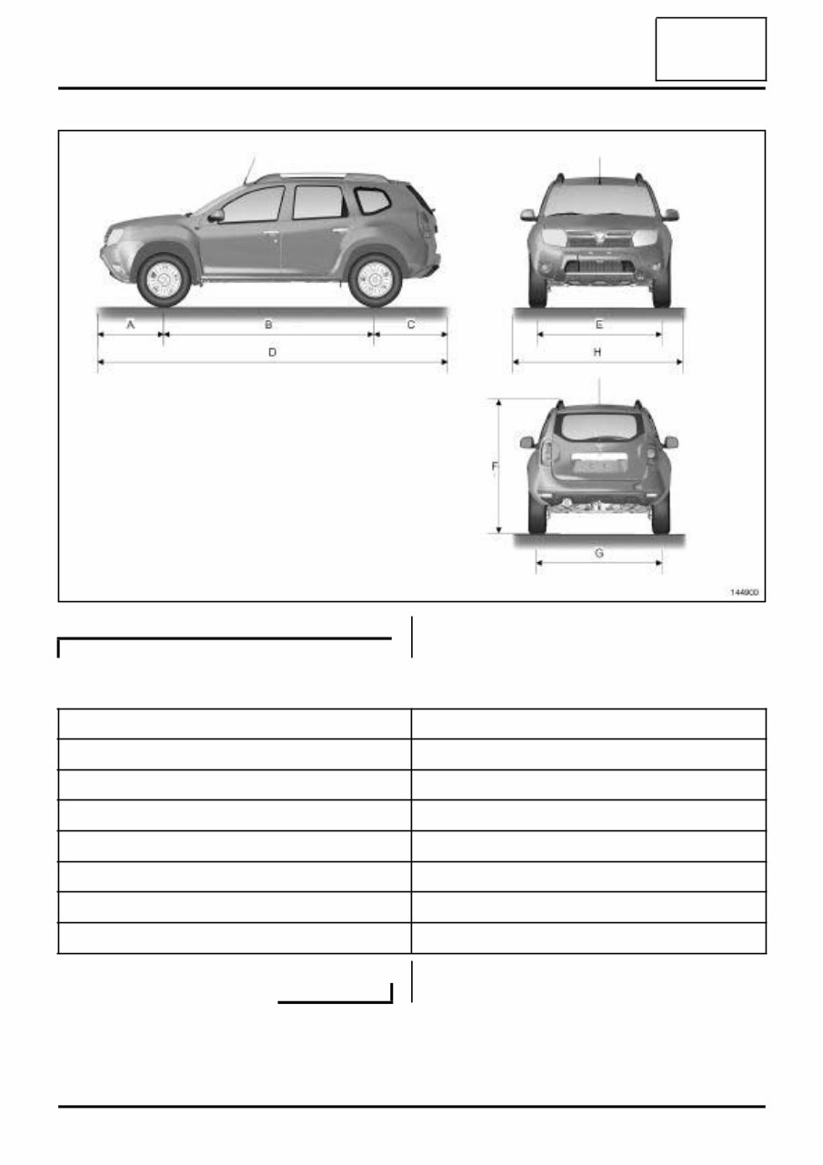
01A- 2 VEHICLE MECHANICAL SPECIFICATIONS Vehicle: Specifications 01A Dimensions in metres: 4X4 TRANSMISSION (A) 0.822 (B) 2.671 (C) 0.822 (D) 4.315 (E) 1.560 (F) (unladen) 1.682 (G) 1.570 (H) 1.822 Engine Gearbox Emissions standard Engine type Engine suf- fix Cubic capac- ity(cc) Gearbox type Gearbox suffix Transmission type K4M 606 1598 TL8 002 4x4 EURO 4 EURO 5 690 JR5 187 4x2 EURO 4 K9K 796 1461 JR5 189 4x2 EURO 4 884 TL8 000 4x4 EURO 1 EURO 3 EURO 4 898 EURO 5
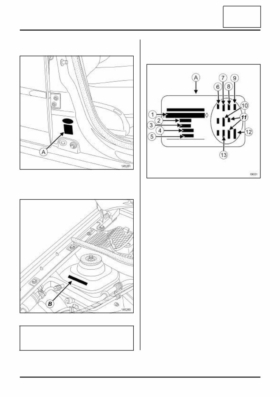
01C-1 VEHICLE BODYWORK SPECIFICATIONS Vehicle: Identification 01C I - LOCATION OF VEHICLE IDENTIFICATION PLATE (A) II - LOCATION OF THE VEHICLE IDENTIFICATION NUMBER (B) III - DETAILED VIEW OF THE VEHICLE IDENTIFICATION PLATE Plate (A) 145261 145260 Note: If the complete body is being replaced, it must be marked in compliance with the current regulations. 19031 (1) Vehicle type and type number; this information also appears on marking (B) (2) MGVW (Maximum Gross Vehi- cle Weight) (3) GTW (Gross train weight, vehi- cle under load with trailer) (4) Maximum permissible front axle load (5) Maximum permissible rear axle load (6) Vehicle technical specifications (7) Paintwork reference number (8) Equipment level (9) Vehicle type (10) Upholstery code (11) Additional equipment details (12) Production number (13) Interior tr im code
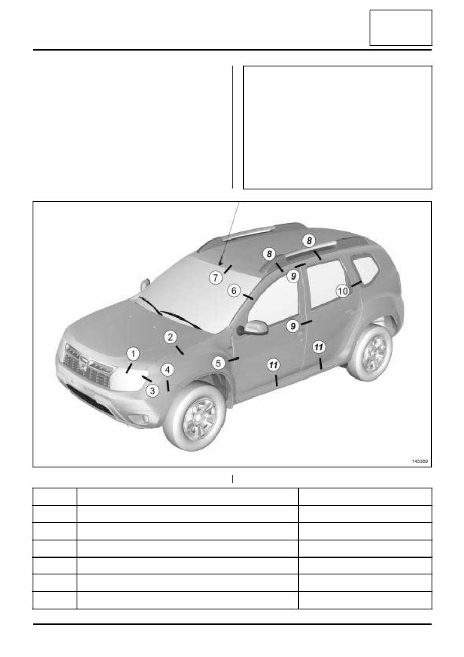
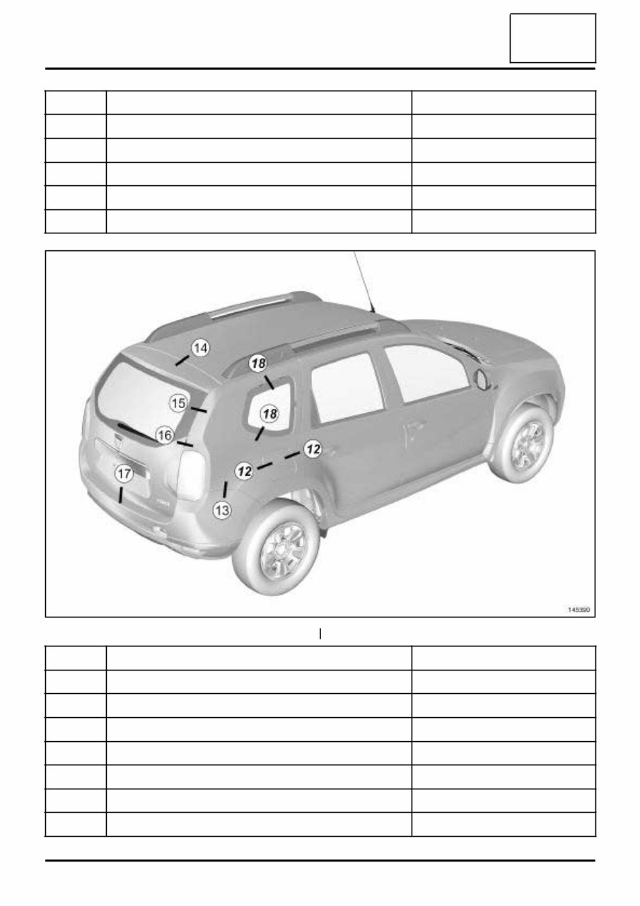
01C-2 VEHICLE BODYWORK SPECIFICATIONS Vehicle panel gaps: Adjustment value 01C WARNING The clearance values are given for information pur- poses. When adjusting clearances, certain rules have to be followed: - maintain symmetry with respect to the opposite side, - ensure the flush fitting is correct, - check correct operation of the opening, and water/ air-tightness. 145389 No. Location Clearances (mm) (1) bonnet / headlight 5 ± 2 (2) bonnet / front wing 4 ± 1.5 (3) headlight / front wing 2 ± 1.5 (4) front bumper / front wing 0.5 (5) front side door / front wing 4.5 ± 1 (6) front side door / windscreen pillar 18 ± 1
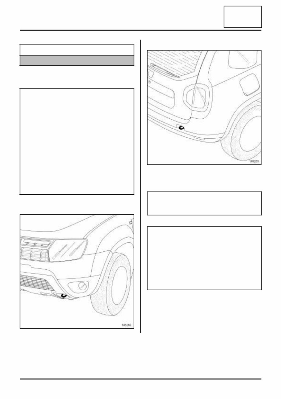
02A- 1 LIFTING EQUIPMENT Vehicle: Towing and lifting 02A I - TOWING 1 - Position of front attachment point 2 - Position of rear attachment point II - LIFTING BY TROLLEY JACK Equipment required safety strap(s) WARNING See the current towing regulations in each country. Never use the driveshafts, axle assembly compo- nents or suspension components as attachment points. Tighten and lock the towing ring before use. Always pull in the direction of the rod's length in order to avoid breaking it. Vehicles fitted with automatic transmission: - It is preferable to transport the vehicle on a flatbed or to tow it by lifting the front wheels; as an excep- tion, the vehicle can be towed with the wheels on the ground, but at a speed of less than 12 mph (20 km/h) over a maximum distance of 18 miles (30 km) (with the gear lever in neutral). 145262 145263 IMPORTANT Appropriate axle stands must be used if a trolley jack is used. WARNING The subframe of this vehicle is protected by prod- ucts providing a 6-year anti-corrosion warranty. Never use equipment not fitted with rubber pads, to avoid direct metal to metal contact which could damage the original protection. The vehicle must not be raised by support points under the front suspension arms or under the rear axle.
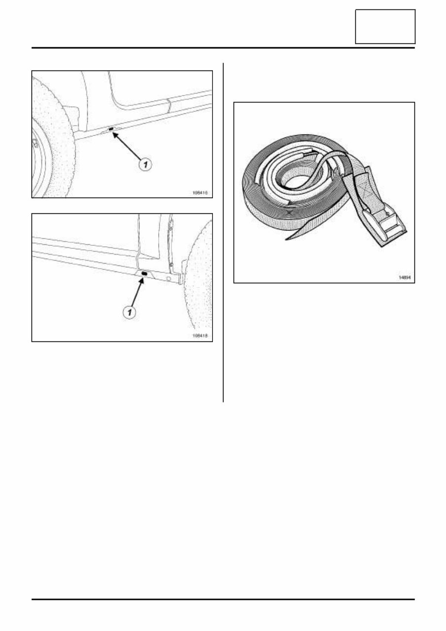
02A- 2 LIFTING EQUIPMENT Vehicle: Towing and lifting 02A To raise a front or rear wheel, use (1) as the support point. To mount the vehicle on axle stands, the entire vehicle must be lifted on one side and axle stands must be placed under the jacking points for the tool kit jack (1) . III - LIFTING ON A LIFT 1 - Safety advice reminder If it is necessary to remove heavy components from the vehicle, it is preferable to use a four-post lift. After removing certain components (e.g. engine and transmission assembly, rear axle, fuel tank, etc.), there is a danger that the vehicle will tip on a two post lift. When the vehicle is raised on an underbody two post lift, fit safety strap(s), part no. 77 11 172 554 available from the Parts Department. 108416 108418 14894
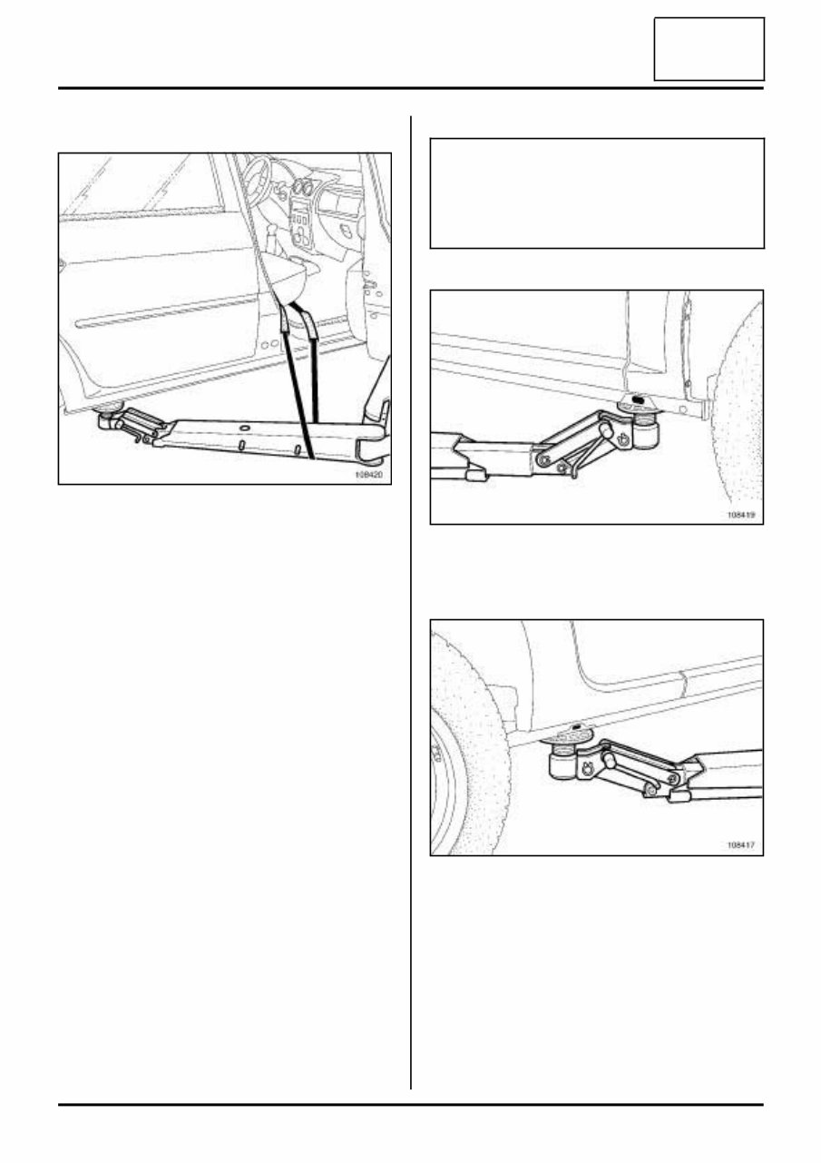
02A- 3 LIFTING EQUIPMENT Vehicle: Towing and lifting 02A 2 - Fitting the straps For safety purposes, the straps must always be in per- fect condition; replace them if they are damaged. When fitting the straps, check that the seats and fragile parts of the vehicle are correctly protected. a - Tilting towards the front Pass the strap under the rear right-hand arm of the lift. Pass the strap through the inside of the vehicle. Pass the strap under the rear left-hand arm of the lift. Pass the belt through the inside of the vehicle again. Tighten the strap. b - Tilting towards the rear Pass the strap under the front right-hand arm of the lift. Pass the strap through the inside of the vehicle. Pass the strap under the front left-hand arm of the lift. Pass the belt through the inside of the vehicle again. Tighten the strap. 3 - Permitted jacking points To raise the vehicle, position the pads of the lift arms as indicated below taking care not to damage the end of the front wing or the underside of the sill panel. At the front Position the lift arms under the end of the sill panel body flanges. At the rear Position the lift arms under the end of the sill panel body flanges. 108420 IMPORTANT Only the jacking points described in this section allow the vehicle to be raised in complete safety. Do not raise the vehicle using points other than those described in this section. 108419 108417
Find the most complete service and repair manual for RENAULT DUSTER 2013. This professional technical manual contains service, maintenance, and troubleshooting information for your RENAULT DUSTER 2013. It is the manual used in the local service repair shop and is guaranteed to be fully useful to save your precious time.
The RENAULT DUSTER 2013 Service Manual has easy to read text sections with top quality diagrams and instructions. They are specifically written for both do-it-yourself enthusiasts and experienced mechanics. With step-by-step instructions and highly detailed exploded pictures, diagrams to show you how to complete the required job correctly and efficiently. The manual covers every single detail on your machine and provides step-by-step instructions based on the complete disassembly of the machine.
This manual service is packed with all the information you need and is very simple to use. Accurate, clear, and concise text, combined with illustrations, make it possible for anyone with even a bit of basic mechanical knowledge to safely and easily service and repair their RENAULT DUSTER 2013.
Comprehensive diagrams, in-depth illustrations, and all the manufacturer's specifications and technical information you will need are included. With our able Repair Manuals, find the page pertaining to your job, print it off, and get working on your machine. No more ruining your expensive paper shop manual with grease and dirt.
Get instant access to your manual! No waiting, no shipping fee, no waiting nervously for the postal delivery, you can start doing your repairs right away! Broken down on the trail or site and have a smartphone? With our able Repair Manuals, you instantly have access to the material needed to get you running again. Kind of tough to do that with a paper manual.
Service and repair manual for RENAULT DUSTER 2013.
File Format: .PDF
Language: English
Specifications: Full Printable
Zoom IN/OUT: YES
Delivery: Instant Access
Requirements: Adobe Reader & Win
Compatible: All Versions of Windows & Mac
Living with your RENAULT DUSTER 2013:
MOT Test Checks
Roadside Repairs
Routine Maintenance
Engine and Associated Systems
Engine removal and general engine overhaul procedures
Cooling, heating and air conditioning systems
Fuel and exhaust systems
Engine electrical systems
Emissions control systems
Transmission
Manual transmission
Automatic transmission
Clutch and driveshafts
Brakes
Braking system
Suspension
Suspension and steering systems
Body Equipment
Bodywork and fittings
Electrical
Body electrical systems
Wiring Diagrams
REFERENCE
Tools and Working Facilities
General Repair Procedures
Buying spare parts and vehicle identification numbers