ACC-1 ENGINE C D E F G H I J K L M SECTION ACC A ACC N O P CONTENTS ACCELERATOR CONTROL SYSTEM PRECAUTION .............................................. 2 PRECAUTIONS .................................................. 2 Precaution for Supplemental Restraint System (SRS) "AIR BAG" and "SEAT BELT PRE-TEN- SIONER" .................................................................. 2 REMOVAL AND INSTALLATION ............... 3 ACCELERATOR CONTROL SYSTEM .............. 3 Component .............................................................. 3 Removal and Installation ......................................... 3 SERVICE DATA AND SPECIFICATIONS (SDS) ............................................................ 5 SERVICE DATA AND SPECIFICATIONS (SDS) .................................................................. 5 Accelerator Control .................................................. 5
ACC-2 < PRECAUTION > PRECAUTIONS PRECAUTION PRECAUTIONS Precaution for Supplemental Restraint System (SRS) "AIR BAG" and "SEAT BELT PRE-TENSIONER" INFOID:0000000004064152 The Supplemental Restraint System such as “AIR BAG” and “SEAT BELT PRE-TENSIONER”, used along with a front seat belt, helps to reduce the risk or severity of injury to the driver and front passenger for certain types of collision. This system includes seat belt switch inputs and dual stage front air bag modules. The SRS system uses the seat belt switches to determine the front air bag deployment, and may only deploy one front air bag, depending on the severity of a collision and whether the front occupants are belted or unbelted. Information necessary to service the system safely is included in the SR and SB section of this Service Man- ual. WARNING: • To avoid rendering the SRS inoperative, which could increase the risk of personal injury or death in the event of a collision which would result in air bag inflation, all maintenance must be performed by an authorized NISSAN/INFINITI dealer. • Improper maintenance, including incorrect removal and installation of the SRS, can lead to personal injury caused by unintentional activation of the system. For removal of Spiral Cable and Air Bag Module, see the SR section. • Do not use electrical test equipment on any circuit related to the SRS unless instructed to in this Service Manual. SRS wiring harnesses can be identified by yellow and/or orange harnesses or har- ness connectors.
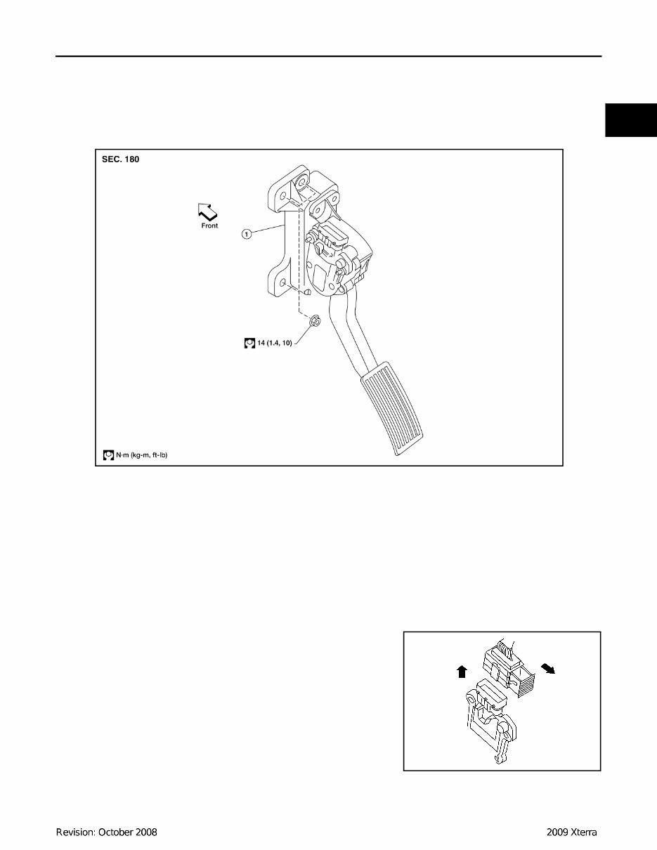
ACCELERATOR CONTROL SYSTEM ACC-3 < REMOVAL AND INSTALLATION > C D E F G H I J K L M A ACC N P O REMOVAL AND INSTALLATION ACCELERATOR CONTROL SYSTEM Component INFOID:0000000004064153 CAUTION: • Do not disassemble the accelerator pedal assembly. • Do not remove the accelerator pedal position sensor from the accelerator pedal bracket. • Avoid damage from dropping the accelerator pedal assembly during handling. • Keep the accelerator pedal assembly away from water. Removal and Installation INFOID:0000000004064154 REMOVAL 1. Disconnect the negative battery terminal. 2. Disconnect the accelerator position sensor electrical connector. a. Pull the connector lock back to unlock the connector from the accelerator pedal position sensor as shown. b. Pull up on the connector to disconnect it from the accelerator pedal position sensor as shown. 3. Remove the two upper and one lower accelerator pedal nuts. 4. Remove the accelerator pedal assembly. CAUTION: • Do not disassemble the accelerator pedal assembly. • Do not remove the accelerator pedal position sensor from the accelerator pedal bracket. • Avoid damage from dropping the accelerator pedal assembly during handling. • Keep the accelerator pedal assembly away from water. 1. Non-adjustable accelerator pedal assembly VAH@ / 483D KAH@ / 222D
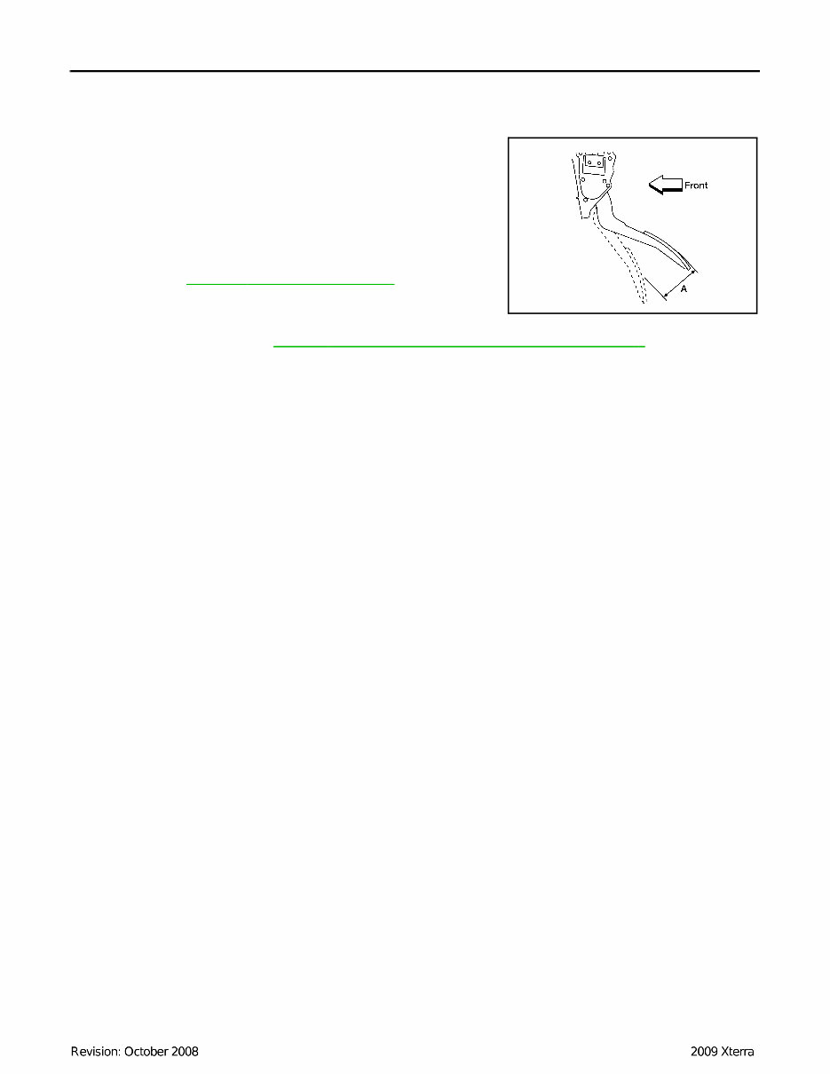
ACC-4 < REMOVAL AND INSTALLATION > ACCELERATOR CONTROL SYSTEM INSTALLATION Installation is in the reverse order of removal. INSPECTION AFTER INSTALLATION • Check that the accelerator pedal moves smoothly within the speci- fied range. • Check that the accelerator pedal smoothly returns to the original position. • Perform an electrical inspection of the accelerator pedal position sensor. Refer to EC-367, " Component Inspection " . CAUTION: When the harness connector of the accelerator pedal position sensor is disconnected, perform ″Accelerator Pedal Released Position Learning″. Refer to EC-19, " Accelerator Pedal Released Position Learning " . Accelerator pedal - total pedal applied stroke “A” : 48 mm (1.89 in) KAH@ / 323D
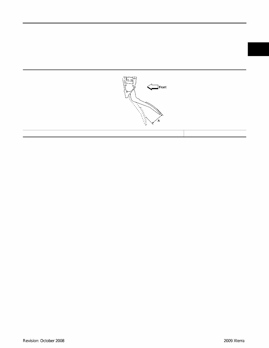
SERVICE DATA AND SPECIFICATIONS (SDS) ACC-5 < SERVICE DATA AND SPECIFICATIONS (SDS) C D E F G H I J K L M A ACC N P O SERVICE DATA AND SPECIFICATIONS (SDS) SERVICE DATA AND SPECIFICATIONS (SDS) Accelerator Control INFOID:0000000004064155 ACCELERATOR PEDAL Unit: mm (in) Accelerator pedal - total pedal applied stroke “A” 48 (1.89) KAH@ / 323D
The 2008 Nissan Xterra Service & Repair Manual is your ultimate guide to fixing problems on your vehicle. With step-by-step instructions, clear images, and exploded-view illustrations provided by the manufacturer, this repair manual is a must-have for any DIY enthusiast.
Regular maintenance is crucial for the durability of your vehicle. Even the toughest cars will eventually need replacement parts. With this manual, you'll have access to the manufacturer's recommended troubleshooting charts and replacement procedures, allowing you to save on repairs and increase your vehicle's reliability.
No need to flip through hundreds of pages or worry about greasy or lost pages. This manual is easily accessible on any electronic device, including PC and Mac computers, as well as Android and Apple smartphones and tablets. You can even print out a physical copy if you prefer.
Don't let car troubles stress you out. With the 2008 Nissan Xterra Service & Repair Manual, you'll have all the necessary information at your fingertips to keep your vehicle running smoothly and save on costly repairs. Trust in this comprehensive manual to keep your repair shop visits to a minimum.