HAC-1 VENTILATION, HEATER & AIR CONDITIONER C D E F G H J K L M SECTION HAC A B HAC N O P CONTENTS HEATER & AIR CONDITIONING CONTROL SYSTEM MANUAL AIR CONDITIONING PRECAUTION .............................................. 3 PRECAUTIONS .................................................. 3 Precaution for Supplemental Restraint System (SRS) "AIR BAG" and "SEAT BELT PRE-TEN- SIONER" .................................................................. 3 Precaution for Work ................................................. 3 Working with HFC-134a (R-134a) ............................ 3 Service Equipment ................................................... 4 PREPARATION ........................................... 7 PREPARATION .................................................. 7 Special Service Tool ................................................ 7 Commercial Service Tool ......................................... 7 SYSTEM DESCRIPTION ............................. 8 COMPONENT PARTS ....................................... 8 Component Parts Location ....................................... 8 Component Description ............................................ 9 SYSTEM ............................................................10 MANUAL AIR CONDITIONING SYSTEM ................ 10 MANUAL AIR CONDITIONING SYSTEM : Sys- tem Diagram ........................................................... 10 MANUAL AIR CONDITIONING SYSTEM : Sys- tem Description ...................................................... 10 MANUAL AIR CONDITIONING SYSTEM : Com- pressor Control ....................................................... 10 MANUAL AIR CONDITIONING SYSTEM : Door Control .................................................................... 11 OPERATION ......................................................14 Switch Name and Function .................................... 14 DIAGNOSIS SYSTEM (BCM) ...........................15 COMMON ITEM ........................................................ 15 COMMON ITEM : CONSULT Function (BCM - COMMON ITEM) ....................................................15 AIR CONDITIONER ..................................................16 AIR CONDITIONER : CONSULT Function (BCM - AIR CONDITIONER) ..............................................16 ECU DIAGNOSIS INFORMATION ............. 17 BCM, ECM, IPDM E/R ....................................... 17 List of ECU Reference ............................................17 WIRING DIAGRAM ..................................... 18 MANUAL AIR CONDITIONING SYSTEM ......... 18 Wiring Diagram .......................................................18 MANUAL HEATER SYSTEM ............................ 23 Wiring Diagram .......................................................23 BASIC INSPECTION .................................. 25 DIAGNOSIS AND REPAIR WORKFLOW ........ 25 Workflow .................................................................25 OPERATION INSPECTION .............................. 27 Work Procedure ......................................................27 DTC/CIRCUIT DIAGNOSIS ........................ 29 A/C ON SIGNAL ................................................ 29 Component Function Check ...................................29 Diagnosis Procedure ..............................................29 Component Inspection ............................................30 BLOWER FAN ON SIGNAL ............................. 32 Component Function Check ...................................32 Diagnosis Procedure ..............................................32 A/C INDICATOR ................................................ 34 Diagnosis Procedure ..............................................34 FRONT BLOWER MOTOR ............................... 35 Description ..............................................................35 Revision: July 2011 2012 Versa Sedan
HAC-2 Diagnosis Procedure ............................................. 35 Component Inspection (Front Blower Motor) ......... 37 Component Inspection (Blower Relay) .................. 37 Component Inspection (Front Blower Motor Re- sistor) ..................................................................... 37 Component Inspection (Fan Switch) ..................... 37 MAGNET CLUTCH ........................................... 39 Description ............................................................. 39 Component Function Check .................................. 39 Diagnosis Procedure ............................................. 39 SYMPTOM DIAGNOSIS ............................ 41 MANUAL AIR CONDITIONING SYSTEM ........ 41 Symptom Table ..................................................... 41 INSUFFICIENT COOLING ................................ 42 Description ............................................................. 42 Diagnosis Procedure ............................................. 42 INSUFFICIENT HEATING ................................ 43 Description ............................................................. 43 Diagnosis Procedure ............................................. 43 COMPRESSOR DOES NOT OPERATE .......... 44 Description ............................................................. 44 Diagnosis Procedure ............................................. 44 UNIT REMOVAL AND INSTALLATION .... 45 CONTROL PANEL ........................................... 45 Exploded View ....................................................... 45 Removal and Installation ........................................ 45 THERMO CONTROL AMPLIFIER ................... 46 Exploded View ....................................................... 46 Removal and Installation ........................................ 46 REFRIGERANT PRESSURE SENSOR ........... 47 Removal and Installation for Refrigerant Pressure Sensor .................................................................... 47 BLOWER FAN RESISTOR .............................. 48 Exploded View ....................................................... 48 Removal and Installation ........................................ 48 DOOR CABLE .................................................. 49 Exploded View ....................................................... 49 INTAKE DOOR CABLE ........................................... 49 INTAKE DOOR CABLE : Removal and Installation ... 49 INTAKE DOOR CABLE : Adjustment .................... 49 MODE DOOR CABLE .............................................. 50 MODE DOOR CABLE : Removal and Installation ... 50 MODE DOOR CABLE : Adjustment ....................... 50 AIR MIX DOOR CABLE ........................................... 50 AIR MIX DOOR CABLE : Removal and Installation ... 50 AIR MIX DOOR CABLE : Adjustment .................... 51 Revision: July 2011 2012 Versa Sedan
PRECAUTIONS HAC-3 < PRECAUTION > [MANUAL AIR CONDITIONING] C D E F G H J K L M A B HAC N O P PRECAUTION PRECAUTIONS Precaution for Supplemental Restraint System (SRS) "AIR BAG" and "SEAT BELT PRE-TENSIONER" INFOID:0000000007732969 The Supplemental Restraint System such as “AIR BAG” and “SEAT BELT PRE-TENSIONER”, used along with a front seat belt, helps to reduce the risk or severity of injury to the driver and front passenger for certain types of collision. This system includes seat belt switch inputs and dual stage front air bag modules. The SRS system uses the seat belt switches to determine the front air bag deployment, and may only deploy one front air bag, depending on the severity of a collision and whether the front occupants are belted or unbelted. Information necessary to service the system safely is included in the SR and SB section of this Service Man- ual. WARNING: • To avoid rendering the SRS inoperative, which could increase the risk of personal injury or death in the event of a collision which would result in air bag inflation, all maintenance must be performed by an authorized NISSAN/INFINITI dealer. • Improper maintenance, including incorrect removal and installation of the SRS, can lead to personal injury caused by unintentional activation of the system. For removal of Spiral Cable and Air Bag Module, see the SR section. • Do not use electrical test equipment on any circuit related to the SRS unless instructed to in this Service Manual. SRS wiring harnesses can be identified by yellow and/or orange harnesses or har- ness connectors. PRECAUTIONS WHEN USING POWER TOOLS (AIR OR ELECTRIC) AND HAMMERS WARNING: • When working near the Airbag Diagnosis Sensor Unit or other Airbag System sensors with the Igni- tion ON or engine running, DO NOT use air or electric power tools or strike near the sensor(s) with a hammer. Heavy vibration could activate the sensor(s) and deploy the air bag(s), possibly causing serious injury. • When using air or electric power tools or hammers, always switch the Ignition OFF, disconnect the battery, and wait at least 3 minutes before performing any service. Precaution for Work INFOID:0000000007733812 • When removing or disassembling each component, be careful not to damage or deform it. If a component may be subject to interference, be sure to protect it with a shop cloth. • When removing (disengaging) components with a screwdriver or similar tool, be sure to wrap the component with a shop cloth or vinyl tape to protect it. • Protect the removed parts with a shop cloth and prevent them from being dropped. • Replace a deformed or damaged clip. • If a part is specified as a non-reusable part, always replace it with new one. • Be sure to tighten bolts and nuts securely to the specified torque. • After installation is complete, be sure to check that each part works properly. • Follow the steps below to clean components. - Water soluble dirt: Dip a soft cloth into lukewarm water, and wring the water out of the cloth to wipe the dirty area. Then rub with a soft and dry cloth. - Oily dirt: Dip a soft cloth into lukewarm water with mild detergent (concentration: within 2 to 3%), and wipe the dirty area. Then dip a cloth into fresh water, and wring the water out of the cloth to wipe the detergent off. Then rub with a soft and dry cloth. • Do not use organic solvent such as thinner, benzene, alcohol, or gasoline. • For genuine leather seats, use a genuine leather seat cleaner. Working with HFC-134a (R-134a) INFOID:0000000007732972 WARNING: • CFC-12 (R-12) refrigerant and HFC-134a (R-134a) refrigerant are not compatible. If the refrigerants are mixed compressor failure is likely to occur. Refer to HA-5, " Precautions For Refrigerant System Revision: July 2011 2012 Versa Sedan
HAC-4 < PRECAUTION > [MANUAL AIR CONDITIONING] PRECAUTIONS Service " . To determine the purity of HFC-134a (R-134a) in the vehicle and recovery tank, use Refrig- erant Recovery/Recycling Recharging equipment and Refrigerant Identifier. • Use only specified oil for the HFC-134a (R-134a) A/C system and HFC-134a (R-134a) components. If oil other than that specified is used, compressor failure is likely to occur. • The specified HFC-134a (R-134a) oil rapidly absorbs moisture from the atmosphere. The following handling precautions must be observed: - When removing refrigerant components from a vehicle, immediately cap (seal) the component to minimize the entry of moisture from the atmosphere. - When installing refrigerant components to a vehicle, do not remove the caps (unseal) until just before connecting the components. Connect all refrigerant loop components as quickly as possible to minimize the entry of moisture into system. - Only use the specified oil from a sealed container. Immediately reseal containers of oil. Without proper sealing, oil will become moisture saturated and should not be used. - Avoid breathing A/C refrigerant and oil vapor or mist. Exposure may irritate eyes, nose and throat. Remove HFC-134a (R-134a) from the A/C system using certified service equipment meeting require- ments of SAE J2210 [HFC-134a (R-134a) recycling equipment], or J2209 [HFC-134a (R-134a) recy- cling equipment]. If accidental system discharge occurs, ventilate work area before resuming service. Additional health and safety information may be obtained from refrigerant and oil manufac- turers. - Do not allow A/C oil to come in contact with styrofoam parts. Damage may result. CONTAMINATED REFRIGERANT If a refrigerant other than pure HFC-134a (R-134a) is identified in a vehicle, your options are: • Explain to the customer that environmental regulations prohibit the release of contaminated refrigerant into the atmosphere. • Explain that recovery of the contaminated refrigerant could damage your service equipment and refrigerant supply. • Suggest the customer return the vehicle to the location of previous service where the contamination may have occurred. • If you choose to perform the repair, recover the refrigerant using only dedicated equipment and contain- ers. Do not recover contaminated refrigerant into your existing service equipment. If your facility does not have dedicated recovery equipment, you may contact a local refrigerant product retailer for available ser- vice. This refrigerant must be disposed of in accordance with all federal and local regulations. In addition, replacement of all refrigerant system components on the vehicle is recommended. • If the vehicle is within the warranty period, the air conditioner warranty is void. Please contact NISSAN Cus- tomer Affairs for further assistance. Service Equipment INFOID:0000000007732973 RECOVERY/RECYCLING EQUIPMENT Follow the manufacturer's instructions for machine operation and machine maintenance. Never introduce any refrigerant other than that specified into the machine. ELECTRONIC LEAK DETECTOR Follow the manufacturer's instructions for tester operation and tester maintenance. VACUUM PUMP Revision: July 2011 2012 Versa Sedan
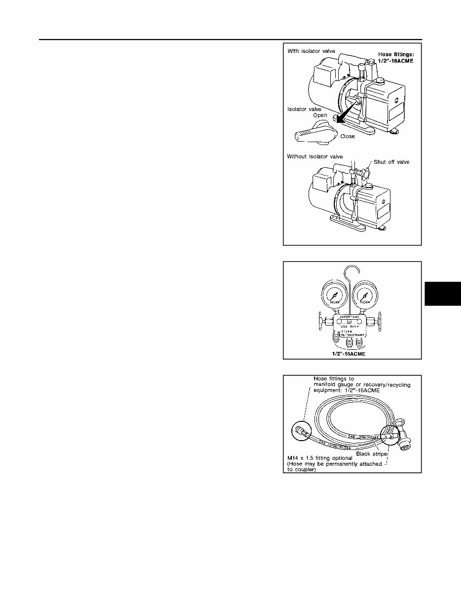
PRECAUTIONS HAC-5 < PRECAUTION > [MANUAL AIR CONDITIONING] C D E F G H J K L M A B HAC N O P The oil contained inside the vacuum pump is not compatible with the specified oil for HFC-134a (R-134a) A/C systems. The vent side of the vacuum pump is exposed to atmospheric pressure so the vac- uum pump oil may migrate out of the pump into the service hose. This is possible when the pump is switched off after evacuation (vac- uuming) and hose is connected to it. To prevent this migration, use a manual valve situated near the hose-to-pump connection, as follows. • Usually vacuum pumps have a manual isolator valve as part of the pump. Close this valve to isolate the service hose from the pump. • For pumps without an isolator, use a hose equipped with a manual shut-off valve near the pump end. Close the valve to isolate the hose from the pump. • If the hose has an automatic shut off valve, disconnect the hose from the pump: as long as the hose is connected, the valve is open and lubricating oil may migrate. Some one-way valves open when vacuum is applied and close under a no vacuum condition. Such valves may restrict the pump's ability to pull a deep vacuum and are not recommended. MANIFOLD GAUGE SET Be certain that the gauge face indicates R-134a or 134a. Make sure the gauge set has 1/2″-16 ACME threaded connections for service hoses. Confirm the set has been used only with refrigerant HFC- 134a (R-134a) along with specified oil. SERVICE HOSES Be certain that the service hoses display the markings described (colored hose with black stripe). All hoses must include positive shut- off devices (either manual or automatic) near the end of the hoses opposite the manifold gauge. SERVICE COUPLERS RHA270D SHA533D RHA272D Revision: July 2011 2012 Versa Sedan
This comprehensive service and repair manual for the 2014 Nissan Versa Sedan is an invaluable resource for mechanics and DIY enthusiasts. Covering all key systems and components, it provides detailed guidance for troubleshooting, maintenance, and repair procedures tailored specifically to this model.
Inside, you’ll find clear step-by-step instructions accompanied by detailed diagrams and specifications. Topics include engine maintenance, transmission servicing, brake system repairs, suspension adjustments, and electrical system troubleshooting, among others. Whether you’re replacing a worn-out component or tackling complex diagnostics, this manual ensures you have the precise information needed.
Designed in a digital format, it allows for easy access on your preferred device, keeping your workspace organized and free of clutter. With its user-friendly structure and detailed content, this manual ensures that every repair and service task is straightforward and manageable, saving you time and effort.
Printable: Yes Language: English Compatibility: Pretty much any electronic device, incl. PC & Mac computers, Android and Apple smartphones & tablet, etc. Requirements: Adobe Reader (free)