

SERVICEMANUAL
NISSAN
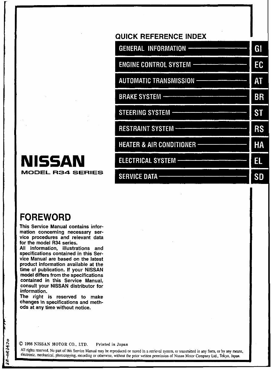
MODEL R34 SERIES
FOREWORD
This Sewice Manual contains infor-
mation concerning necessary ser-
vice procedures and relevant data
for the model R34 series.
All information, illustrations and
specifications contained in this Ser-
vice Manual are based on the latest
product information available at the
time of publication. If your NISSAN
model differs from the specifications
contained in this Sewice Manual,
consult your NISSAN distributor for
information.
The right is resewed to make
changes in specifications and meth-
ods at any time without notice.
QUICK REFERENCE INDEX I
0 1998 KISSAN MOTOR CO., LTD. Printed in Japan
A11 rights reserved. No part of this Service Manual may be reproduced or stored in a retrieval system, or transmitted in any form, or by any means,
electronic, mechanical, photocopying, recording or otherwise, without the prior written permission of Nissan Motor Company Ltd.. Tokyo, Japan.
HOW TO USE THIS MANUAL
b This Service Manual only contains the service data specifications and trouble diagnosis informa-
tion such as self-diagnosis, CONSULT, circuit diagram and so on.
b For other information not specified in this manual, refer to Japanese version Service Manual (Pub.
No. A006029) and wiring diagram manual (Pub. No. WD8EOR34JO).
IMPORTANT SAFETY NOTICE
The proper performance of service is essential for both the safety of the technician and the efficient
functioning of the vehicle.
The service methods in this Service Manual are described in such a manner that the service may be
performed safely and accurately.
Service varies with the procedures used, the skills of the technician and the tools and parts available.
Accordingly, anyone using service procedures, took or parts which are not specifically recommended
by NISSAN must first be completely satisfied that neither personal safety nor the vehicle's safety will
be jeopardized by the service method selected.
GENERAL INFORMATION
SECTION GI
CONTENTS
CONSULT CHECKING SYSTEM .................................... 2 IDENTIFICATION INFORMATION ................................... 3
Function and System Application ................................ 2 Model Variation ............................................................ 3
Lithium Battery Replacement ..................................... .2 Vehicle Identification Number ...................................... 4
.................................................... Checking Equipment 2 Vehicle Identification Plate ........................................... 4
CONSULT CHECKING SYSTEM
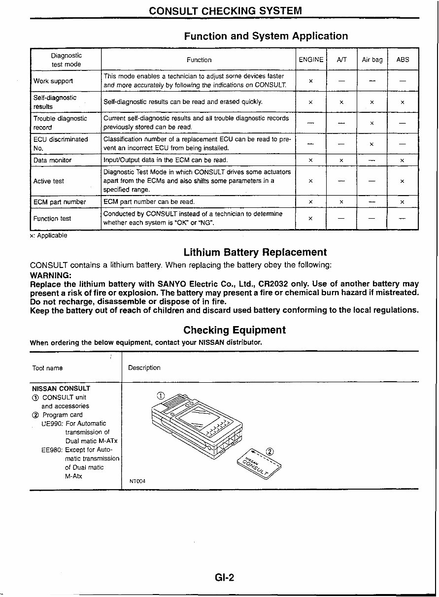
Function and System Application
Diagnostic
test mode
Work support
Self-diagnostic
results
Trouble diagnostic
record
Function
This mode enables a technician to adjust some devices faster
and more accurately by following the indications on CONSULT.
ECU discriminated
No.
Data monitor
I I whether each system is "OK" or 'NG". l x H - 1 -
Conducted by CONSULT instead of a technician to determine
Function test
Self-diagnostic results can be read and erased quickly.
Current self-diagnostic results and all trouble diagnostic records
previously stored can be read.
Active test
ECM part number
L
x: Applicable
ENGINE
x
Classification number of a replacement ECU can be read to pre-
vent an incorrect ECU from being installed.
InputIOutput data in the ECM can be read.
Lithium Battery Replacement
x
Diagnostic Test Mode in which CONSULT drives some actuators
apart from the ECMs and also shifts some parameters in a
specified range.
ECM part number can be read.
CONSULT contains a lithium battery. When replacing the battery obey the following:
WARNING:
Replace the lithium battery with SANYO Electric Co., Ltd., CR2032 only. Use of another battery may
present a risk of fire or explosion. The battery may present a fire or chemical burn hazard if mistreated.
Do not recharge, disassemble or dispose of in fire.
Keep the battery out of reach of children and discard used battery conforming to the local regulations.
AfT
-
-
x
Checking Equipment
x
-
x
x
When ordering the below equipment, contact your NlSSAN distributor.
Air bag
-
-
-
x
!
Tool name
ABS
-
x
X
-
x
NISSAN CONSULT
@ CONSULT unit
and accessories
@ Program card
UE990: For Automatic
transmission of
Dual rnatic M-ATx
EE980: Except for Auto-
matic transmission
of Dual matic
M-Atx
x
-
--
X
-
Description
-
x
-
-
x
x
IDENTIFICATION INFORMATION
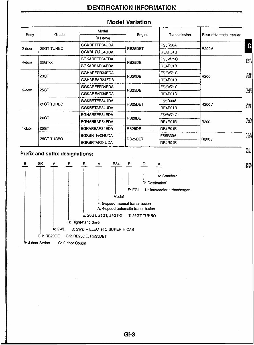
Model Variation
Model
Body Grade Engine Transmission Rear differential carrier
RH drive
GGKBRTFR34UDA FS5R30A
2-door 25GT TURBO RB25DET . R200V
GGKBRTAR34UDA RE4RO1 B
RB20DE
GGHAREARMEDA
1 GGKAREFRMEDA 1 RB25DE
GGKAREARMEDA
GGKBRTFRMUDA
25GT TURBO RB25DET R200V
GGKBRTARMUDA RE4RO1B
BGHAREFR34EDA FS5W71 C
20GT RB20DE
BGHAREARMEDA RE4RO1 B R200 i%
I
BGKBRTFR34UDA FS5R30A $#i
25GT TURBO RB25DET R200V
BGKBRTAR34UDA RE4RO1B
Prefix and suffix designations:
A: Standard
- 1 TEG, TDestlon' U: intercooler turbocharger
Model
F: &speed manual transmission
A: 4-speed automatic transmission
20GT, 25GT, 25GT-X T: 25GT TURBO
k: Right-hand drive
2WD B: 2WD + ELECTRIC SUPER HlCAS
GH: RB20DE GK: RB25DE, RB25DET
4-door Sedan G: 2-door Coupe
IDENTIFICATION INFORMATION
-2 L .I
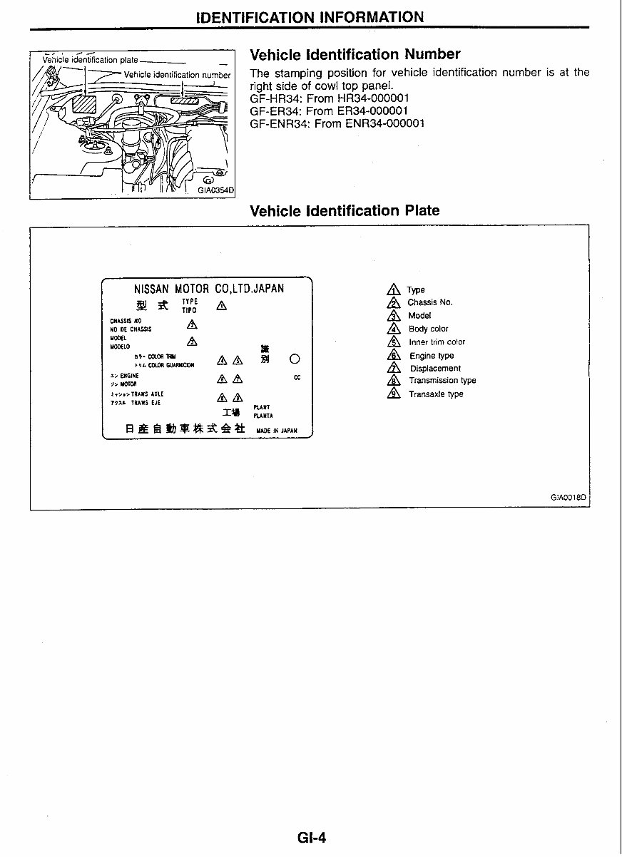
Vehicle identification plate
Vehicle Identification Number
The stamping position for vehicle identification number is at the
right side of cowl top panel.
GF-HR34: From HR34-000001
GF-ER34: From ER34-000001
GF-ENR34: From ENR34-000001
--
Vehicle Identification Plate
-- -
NISSAN MOTOR CO,LTD.JAPAN
CHASSlS NO
YO DE CHASSIS A
MOOEL
WDELO A
n7- me4 W
I
~YLCOLOAWUIWQW( AA
0
z; ENGINE
QA cc
2; Mom
2 I ;mi TRANS AXLE
T77.b TRANS EJE A&
PLANT
nrwrr
A TYP~
A Chassis No.
A Model
A ~ody color
A Inner trim color
A Engine type
Displacement
A Transmission type
A Transaxle type
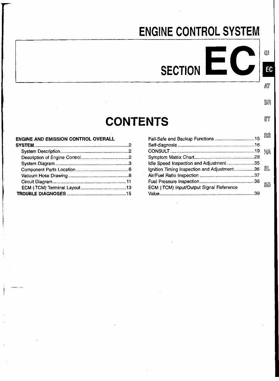
ENGINE CONTROL SYSTEM
SECTION EC
CONTENTS
ENGINE AND EMISSION CONTROL OVERALL
SYSTEM.. ....................................................................... ..2
System Description ...................................................... 2
Description of Engine Control ...................................... 2
System Diagram .......................................................... 3
Component Parts Location .......................................... 6
Vacuum Hose Drawing ................................................ 8
Circuit Diagram ........................................................ 11
.................................... ECM (.EM) Terminal Layout 13
TROUBLE DIAGNOSES ............................................... 15
Fail-safe and Backup Functions 15
RS
...............................
Self-diagnosis .......................................................... 16
CONSULT ..................................................................
I9 MA
............................................... Symptom Matrix Chart 28
Idle Speed Inspection and Adjustment ..................... ;35
................ Ignition Timing Inspection and Adjustment 36
AirIFuel Ratio Inspection ........................................... 37
Fuel Pressure Inspection ........................................... 38
ECM (.TCM) InpuVOutput Signal Reference
9D
......................................................................... Value .39
ENGINE AND EMISSION CONTROL OVERALL SYSTEM
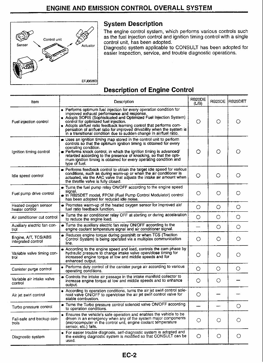
A 1 System Description
The engine control system, which performs various controls such
as the fuel injection control and ignition timing control with a single
control unit, has been adopted.
Diagnostic system applicable to CONSULT has been adopted for
easier inspection, service, and trouble diagnostic operations.
Description of Engine Control
I
Description
\ ,
Performs optimum fuel injection for every operation condition for
improved exhaust performance and response.
Adopts SOFlS (Sophisticated and Optimized Fuel Injection System)
control for optimized fuel injection.
Adopts airbuel ratio feedback learning control that performs com-
0
pensation of airfiuel ratio for improved drivability when the system is
in a transitional condiiion due to sudden change in airfiuel ratro.
Uses an ignition timing map stored in the control unit to perform
controls so that the optimum ignition timing is obtained for every
operating condition.
Performs knock control, in which the ignition timing is advancedl
retarded according to the presence of knocking, so that the opti-
0
mum i nition timing is obtained for every operating condition and
type oPfue1.
Performs feedback control to obtain the target idle speed for various
conditions, such as during warm-up or when the air conditioner is
actuated, via the AAC valve that adjusts the intake air amount when
O
the throttle valve is fully closed.
Turns the fuel pump relay OWOFF according to the engine speed
Fuel injection control
Ignition timing control
Idle speed control
Fuel pump drive
signal.
In RB25DET model, FPCM (Fuel Pump Control Modulatoi) control
O
has been adopted for reduced idle noise.
Heated oxygen sensor
heater control
Air conditioner cut control
Promotes warm-up of the heated oxygen sensor for improved air1
fuel ratio feedback function.
0
Tums the air conditioner relay OFF at starting or during acceleration
to reduce the engine load.
0
--
Auxiliary electric fan con-
trol
Engine, M, TCS,ABS
integrated control
Tums the auxiliary electric fan relay ONIOFF according to the
-
engine coolant temperature signal and air conditioner signal.
Reduces engine toque during gearshift or when TCS (Traction
Control System) is being operated via a multiplex communication
lino
0
- -
Variable valve timing con-
trol
According to the engine speed and load, controls the cam phase by
hydraulic pressure to change intake valve open/close timing for
Increased engine torque at low and middle speeds and for
enhanced out~ut. I o
I
Canister purge control
air intake valve
control
Air jet swirl control
Performs duty control of the canister purge air according to various
ooeratina conditions.
0
-r-~ e-- --- -
Controls the intake air passage in the intake manifold collector to
increase engine torque at low and middle speeds and to enhance
output.
0
According to operation conditions, turns the air jet swirl control sole-
noid valve ONIOFF to openlclose the air jet swirl control valve for
0
pressure control
stable combustion.
Tums the Turbo pressure control solenoid valve ONIOFF according
-
to operation conditions.
Ensures the vehicle's safe operation and enables the vehicle to be
Fail-safe and backup con-
trols
Diagnostic system
driven in an emergency when any of the system major components
(microcomputer in the control unit, engine coolant temperature
0
sensor, etc.) fails.
For easier trouble diagnosis, self-diagnostic system is adopted and
the existing diagnostic system is modified so that CONSULT can be 0
used.
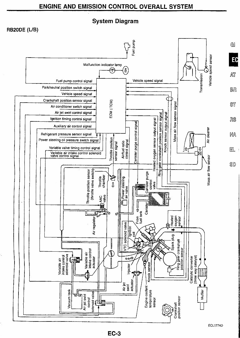
ENGINE AND EMISSION CONTROL OVERALL SYSTEM
RB20DE (UB)
System Diagram
c
!
I-
a
5
a
-
w
2
LL
Malfunction indicator lamp
-!
Fuel pump control signal
Parwneutral position switch signal
C
Vehicle speed signal
-
-
5
Vehicle speed signal -
You're Reading a Preview
What's Included?
Fast Download Speeds
Online & Offline Access
Access PDF Contents & Bookmarks
Full Search Facility
Print one or all pages of your manual
$24.99
Nissan Skyline R34 Workshop Manual
Viewed 15 Times Today

What's Included?
Fast Download Speeds
Online & Offline Access
Access PDF Contents & Bookmarks
Full Search Facility
Print one or all pages of your manual
$24.99

Secure transaction
What's Included?
Fast Download Speeds
Online & Offline Access
Access PDF Contents & Bookmarks
Full Search Facility
Print one or all pages of your manual
Description
The Nissan Skyline R34 Workshop Manual is a detailed resource providing comprehensive information and instructions for servicing and repairing the Nissan Skyline R34. It caters to both professional mechanics and DIY enthusiasts, making it an essential tool for maintaining and restoring this iconic car.
Key features of this workshop manual:
- Complete coverage of all R34 models, including GT-R, GT-T, GT-X, and GT
- Thorough explanations of various systems, components, and procedures
- Detailed diagrams and illustrations for easy understanding
- Diagnostic guides and troubleshooting tips
- Step-by-step instructions for routine maintenance and complex repairs
- Specifications, torque settings, and fluid capacities
- Electrical wiring diagrams
Whether it's a simple oil change or a complex engine overhaul, the Nissan Skyline R34 Workshop Manual is the go-to reference for keeping your Skyline R34 in top-notch condition for years to come.


