Precaution for Supplemental Restraint System (SRS) "AIR BAG" and "SEAT BELT PRE-TENSIONER" The Supplemental Restraint System such as “AIR BAG” and “SEAT BELT PRE-TENSIONER”, used along with a front seat belt, helps to reduce the risk or severity of injury to the driver and front passenger for certain types of collision. Information necessary to service the system safely is included in the SR and SB section of this Service Manual. WARNING: To avoid rendering the SRS inoperative, which could increase the risk of personal injury or death in the event of a collision which would result in air bag inflation, it is recommended that all maintenance and repair be performed by an authorized NISSAN/INFINITI dealer. Improper repair, including incorrect removal and installation of the SRS, can lead to personal injury caused by unintentional activation of the system. For removal of Spiral Cable and Air Bag Module, see the SR section. Do not use electrical test equipment on any circuit related to the SRS unless instructed to in this Service Manual. SRS wiring harnesses can be identified by yellow and/or orange harnesses or harness connectors. PRECAUTIONS WHEN USING POWER TOOLS (AIR OR ELECTRIC) AND HAMMERS WARNING: When working near the Air Bag Diagnosis Sensor Unit or other Air Bag System sensors with the Ignition ON or engine running, DO NOT use air or electric power tools or strike near the sensor(s) with a hammer. Heavy vibration could activate the sensor(s) and deploy the air bag(s), possibly causing serious injury. When using air or electric power tools or hammers, always switch the Ignition OFF, disconnect the battery or batteries, and wait at least three minutes before performing any service.
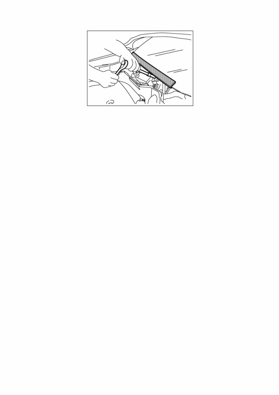
Precaution for Procedure without Cowl Top Cover When performing the procedure after removing cowl top cover, cover the lower end of windshield with urethane, etc to prevent damage to windshield. NISA0000000012787045-01-PIIB3706J
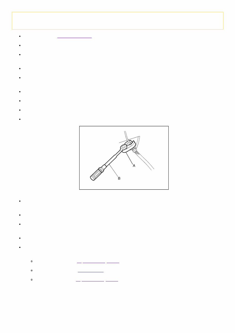
Precaution for Brake System WARNING: Clean any dust from the front brake and rear brake with a vacuum dust collector. Do not blow with compressed air. Brake fluid: Refer to Fluids and Lubricants. Do not reuse drained brake fluid. Do not spill or splash brake fluid on painted surfaces. Brake fluid may damage paint. If brake fluid is splashed on painted areas, wash it away with water immediately. Always confirm the specified tightening torque when installing the brake pipes. After pressing the brake pedal more deeply or harder than normal driving, such as air bleeding, check each item of brake pedal. Adjust brake pedal if it is outside the standard value. Always clean with new brake fluid when cleaning the brake caliper and other components. Do not use mineral oils such as gasoline or light oil to clean. They may damage rubber parts and cause improper operation. Always loosen the brake tube flare nut with a flare nut wrench. Tighten the brake tube flare nut to the specified torque with a flare nut crowfoot (A) and torque wrench (B). NISA0000000012787046-01-JPFIA0001ZZ Brake system is an important safety part. If a brake fluid leak is detected, always disassemble the affected part. If a malfunction is detected, replace part with a new one. Always connect the battery terminals when moving the vehicle. Turn the ignition switch OFF and disconnect the hydraulic booster assembly harness connector or the battery negative terminal before performing the work. Check that no brake fluid leakage is present after replacing the parts. Burnish the brake contact surfaces after refinishing or replacing rotors, after replacing pads, or if a soft pedal occurs at very low mileage. Front disc brake: Refer to Inspection and Adjustment. Rear drum brake: Refer to Brake Burnishing. Rear disc brake: Refer to Inspection and Adjustment.
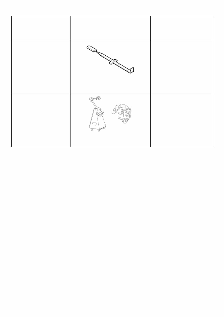
Special Service Tool The actual shape of the tools may differ from those illustrated here. Tool number (TechMate No.) Tool name Description — (J-46532) Brake height tool NISA0000000012787047-01- LFIA0227E Measuring brake pedal height 38-PFM92 ( — ) ProCut™ PFM Series Lathe NISA0000000012787047-02- ALFIA0092ZZ Refinishing rotors
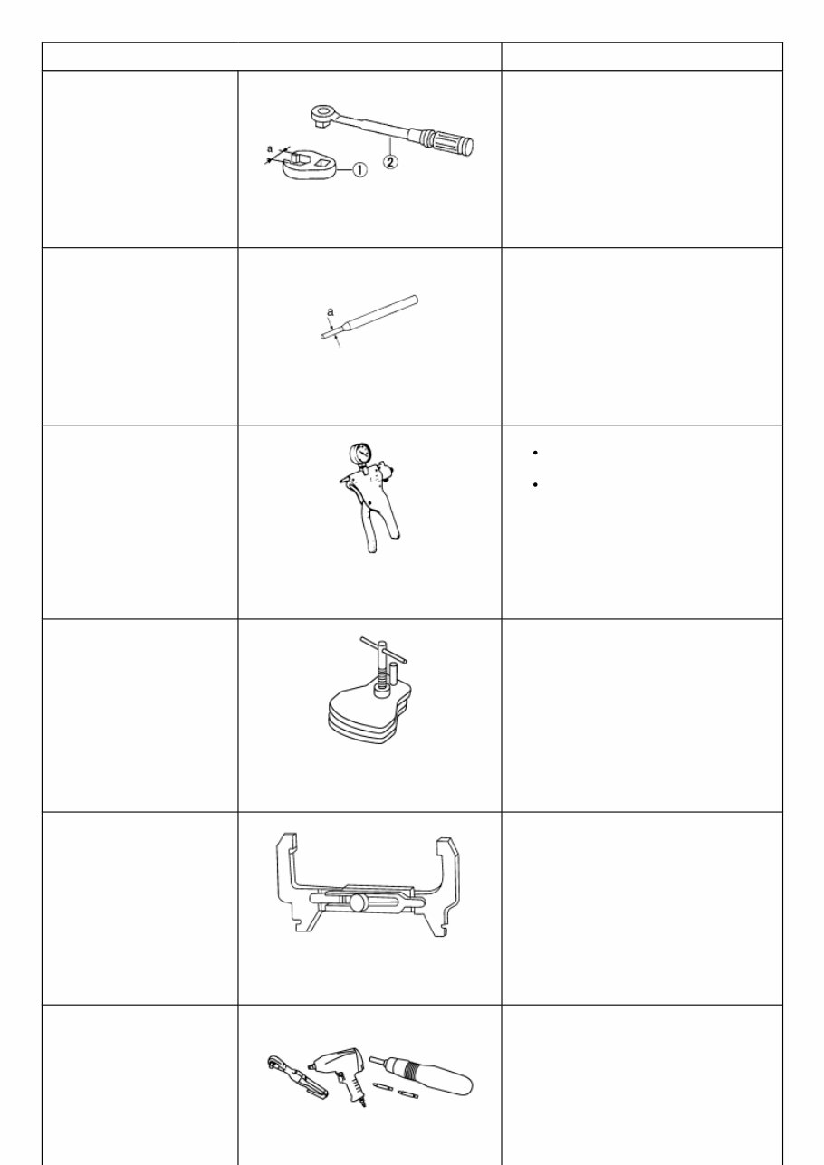
Commercial Service Tool Tool name Description 1. Flare nut crowfoot 2. Torque wrench NISA0000000012787048-01-NT360 Tightening brake tube flare nuts a: 10 mm (0.39 in)/12 mm (0.47 in) Pin punch NISA0000000012787048-02-NT410 Removing and installing reservoir tank a: 4 mm (0.16 in) Vacuum pump NISA0000000012787048-03- ZZC1313D Air tight Inspection of check valve Brake caliper wrench NISA0000000012787048-04- NNFIA0040ZZ Return the piston Brake drum clearance gauge NISA0000000012787048-05- WFIA0167E Measuring rear rotor drum inner diameter Power tool Loosening nuts, screws and bolts
Tool name Description NISA0000000012787048-06- PIIB1407E
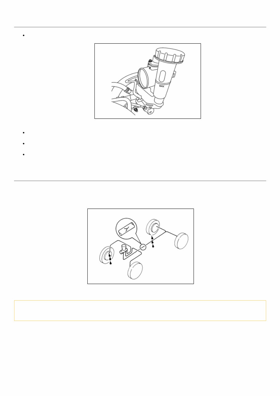
Inspection BRAKE FLUID LEVEL Make sure that the brake fluid level in the reservoir tank is between the MAX and MIN lines. NISA0000000012787051-01-ALDIA0406ZZ Visually check around the reservoir tank for brake fluid leakage. If the brake fluid level is excessively low, check the brake system for leakage. If brake warning lamp remains illuminated after parking brake pedal is released, check the brake system for brake fluid leakage. BRAKE LINE 1 Check brake line (tubes and hoses) for cracks, deterioration or other damage. Replace any damaged parts. 2 Check for brake fluid leakage by depressing brake pedal under a force of 785 N (80 kg-f, 177 lb-ft) for approximately 5 seconds while engine is running. NISA0000000012787051-02-SBR389C CAUTION: If brake fluid leakage occurs around joints, retighten or replace damaged parts as necessary.
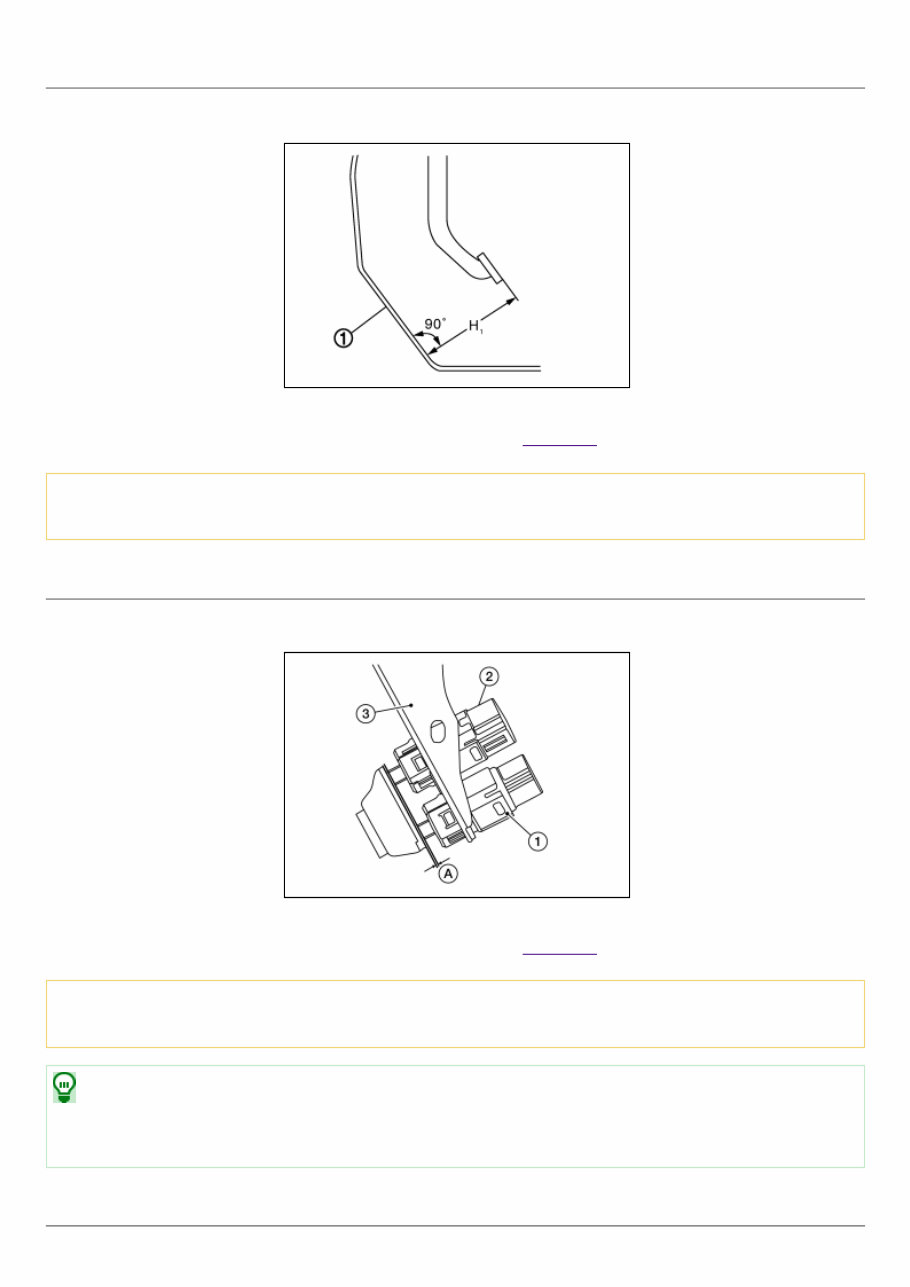
Inspection BRAKE PEDAL HEIGHT Check the brake pedal height (H 1 ) between the dash lower panel (1) and the brake pedal upper surface. NISA0000000012787050-01-JPFIA0065ZZ Brake pedal height (H 1 ) : Refer to Brake Pedal. CAUTION: Check the brake pedal height with the floor trim removed. STOP LAMP SWITCH AND BRAKE PEDAL POSITION SWITCH Check the clearance (A) between the switch assembly bracket (3), the stop lamp switch (2) and the brake pedal position switch (1). NISA0000000012787050-02-ALFIA0248ZZ Clearance (A) : Refer to Brake Pedal. CAUTION: The stop lamp must turn off when the brake pedal is released. NOTE: Pull the brake pedal pad to check that both the stop lamp switch (2) and brake pedal position switch (1) contact ends to brake pedal bracket (3) clearance (A) are within specification. BRAKE PEDAL PLAY Check that brake pedal play does not exist.
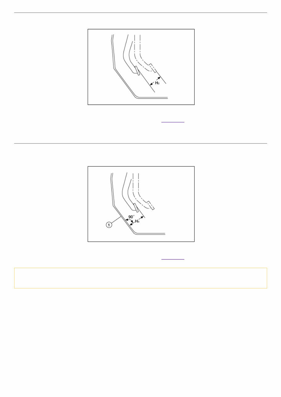
BRAKE PEDAL FULL STROKE Check that the brake pedal moves smoothly within the specified range. NISA0000000012787050-03-AWFIA1119ZZ Brake pedal full stroke (H 2) : Refer to Brake Pedal. DEPRESSED BRAKE PEDAL HEIGHT Check the brake pedal height (H 3 ) between the dash lower panel (1) and the brake pedal upper surface when depressing the brake pedal at 490 N (50 kg, 110 lb) while turning engine ON. NISA0000000012787050-04-AWFIA1120ZZ Depressed brake pedal height (H 3 ) : Refer to Brake Pedal. CAUTION: Check the depressed brake pedal height with the floor trim removed.
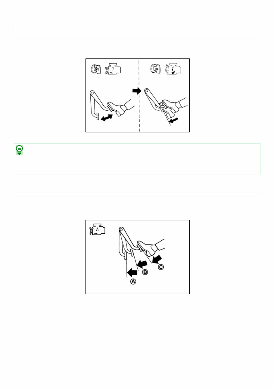
Inspection Operation Depress the brake pedal several times at five second intervals with the engine stopped. Start the engine with the brake pedal fully depressed. Check that the clearance between brake pedal and dash lower panel decreases. NISA0000000012787054-01-BRA0037D NOTE: A slight impact with a small click may be felt on the pedal when the brake pedal is fully depressed. This is normal brake system operation. Vacuum Inspection Idle the engine for one minute to apply vacuum to the brake booster. Stop the engine. Depress the brake pedal several times at five second intervals until the accumulated vacuum is released to atmospheric pressure. Check that the clearance between brake pedal and dash lower panel gradually increases (A → B → C) each time the brake pedal is depressed during this operation. NISA0000000012787054-02-JPFIA0043ZZ Depress the brake pedal with the engine running. Then stop the engine while holding down the brake pedal. Check that the brake pedal stroke does not change after holding down the brake pedal for 30 seconds or more.
The 2016 Nissan Sentra Service & Repair Manual is a comprehensive repair manual for DIY enthusiasts. It includes all necessary troubleshooting and replacement procedures recommended by the manufacturer, making it an essential tool for maintaining the durability of your vehicle.
With step-by-step instructions, clear images, and exploded-view illustrations, this manual provides everything you need to fix your vehicle. You'll no longer have to flip through hundreds of pages or deal with greasy and torn pages; instead, you can easily search, screenshot, or bookmark the information you need.
The 2016 Nissan Sentra Service & Repair Manual is compatible with various electronic devices, including PC and Mac computers, Android and Apple smartphones and tablets. It only requires Adobe Reader, which is available for free.
By following the manufacturer's recommended procedures, you'll be able to save on repairs, increase your vehicle's reliability, and avoid frequent trips to the repair shop. Whether you prefer a digital or physical copy, this manual is a must-have for all 2016 Nissan Sentra owners.